Here's a quick cheat sheet on recommended subnet sizing for Azure. Items in bold are subnet names reserved by the platform for their corresponding service.
One of the hidden gems of Azure is HCM (Hybrid Connection Manager), which addresses the issue of Azure's App Services (Web App, API App, Functions) having the ability to connect to resources hosted in other Azure environments, clouds, or on-premises. In many cases, VPN or ExpressRoute connectivity may be overkill or not a possibility in establishing connectivity to the requested service. The great thing is Hybrid Connections is all the traffic will be egress TCP 443 traffic to Azure via TLS 1.2, which can easily attest to the needs of many secured environments and not require ports to be opened inbound into the environment.
There are two ways to leverage Hybrid Connections for App Services in Azure:
For the purposes of this article, we are going to cover how to connect to a web service "on-premises" via the HCM Agent. While we are using a Web App as an example, keep in mind that this concept can be applied to all App Services such as Web Apps, API Apps, Logic Apps, and Azure Functions. In addition, this article will make a call to a web service on-premises, however keep in mind that HCM is able to connect to any TCP service such as MSSQL, MySQL, Oracle, Web Services, custom TCP service, mainframes, etc.
Tutorial
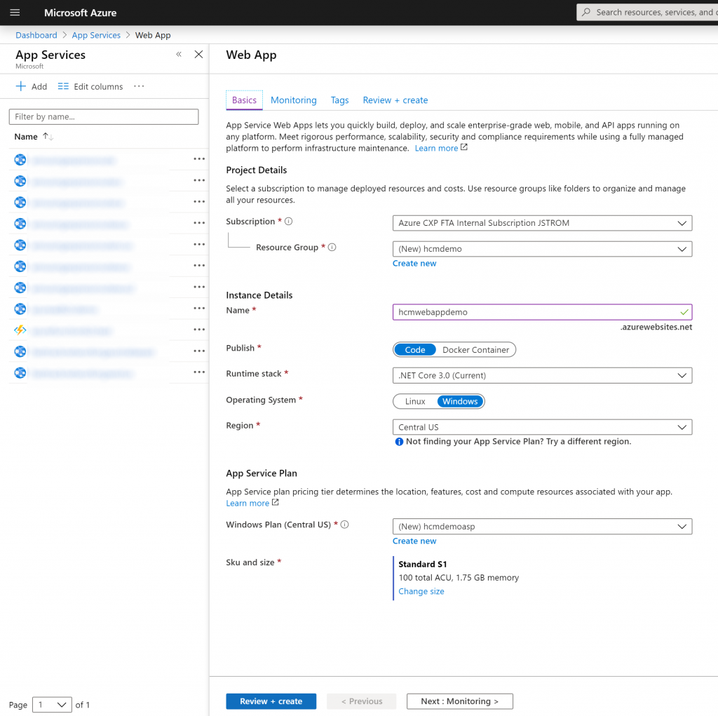
To begin, we will first deploy a Web App from the Azure Portal to give us access to the Hybrid Connection Manager blade. Note: You can leverage any App Service to create the hybrid connection manager instance, but you must be on a paid tier (Free tier will not work).
Select All services -> App Services -> click + Add
Fill out the required information, ensuring you are on a plan greater than Free. Select Review + create and Create
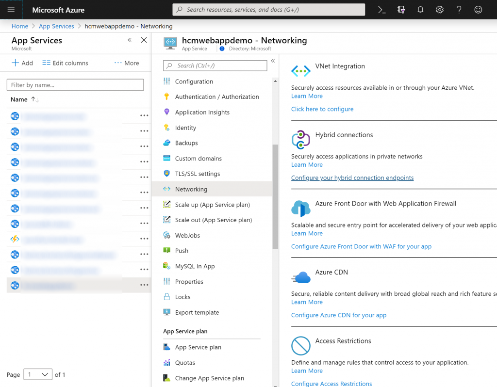
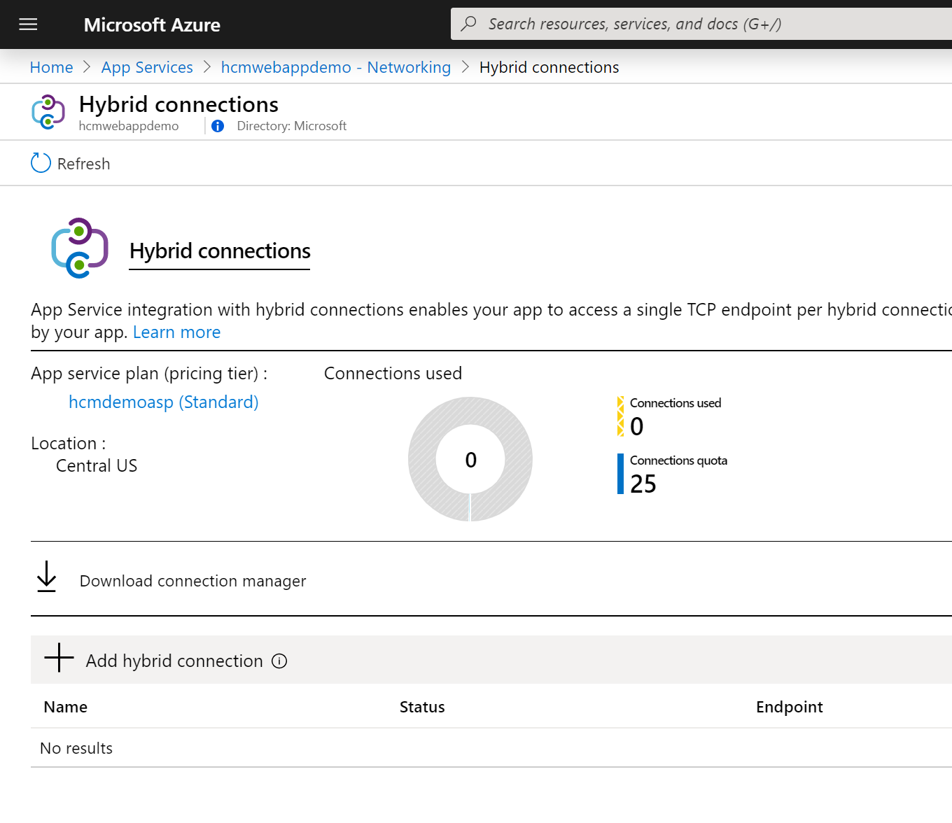
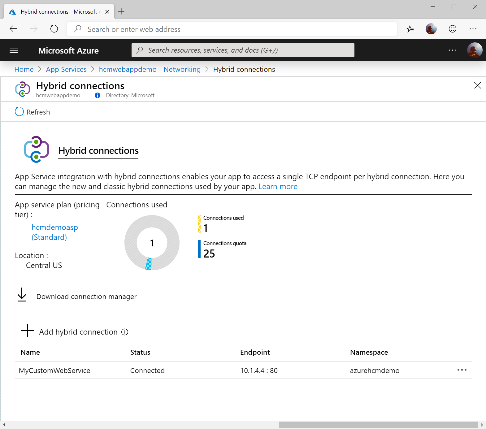
Once deployed, navigate to your Web App, select Networking, and click on Configure your hybrid connection endpoints
On the Hybrid connections screen, click on Download connection manager.
Note: This is the agent you will need to install in the environment that contains the service you are trying to access. The agent itself can be deployed on any machine as long as the machine can access the service you are trying to reach.
Installation of the agent is very straightforward. Complete the steps below.
Select HybridConnectionManager.msi
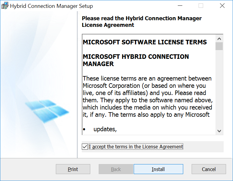
Read the EULA, select I accept the terms in the License Agreement, and click Install
Click Finish
Once installed, navigate back to the Azure Portal (portal.azure.com), click All services -> App Services -> Select your webapp, click Networking, select Configure your hybrid connection endpoints, and click Add hybrid connection.
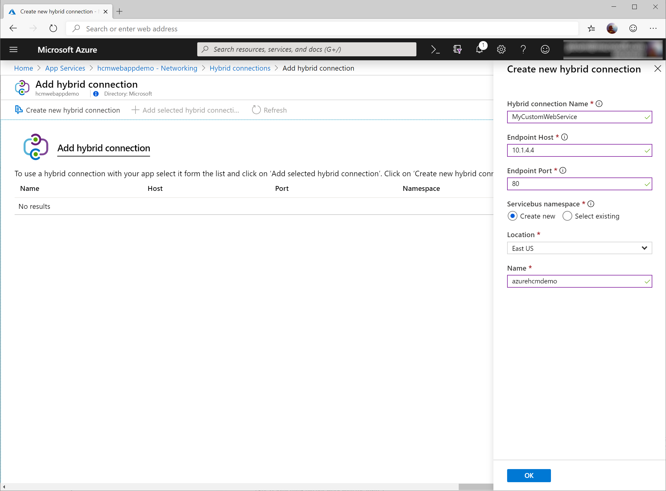
Click Create new hybrid connection and enter the following:
Hybrid connection Name
MyService
Endpoint Host
IPAddress or DNSNameOfTheService
Endpoint Port
PortNumberofYourService
Servicebus namepsace
Create new
Location
Pick the location of the Azure region you want to go to
Name
Enter a unique name for the service bus resource that will be created. This is a globally unique name accross all of Azure and must only consist of lowercase letters, numbers, and hyphens.
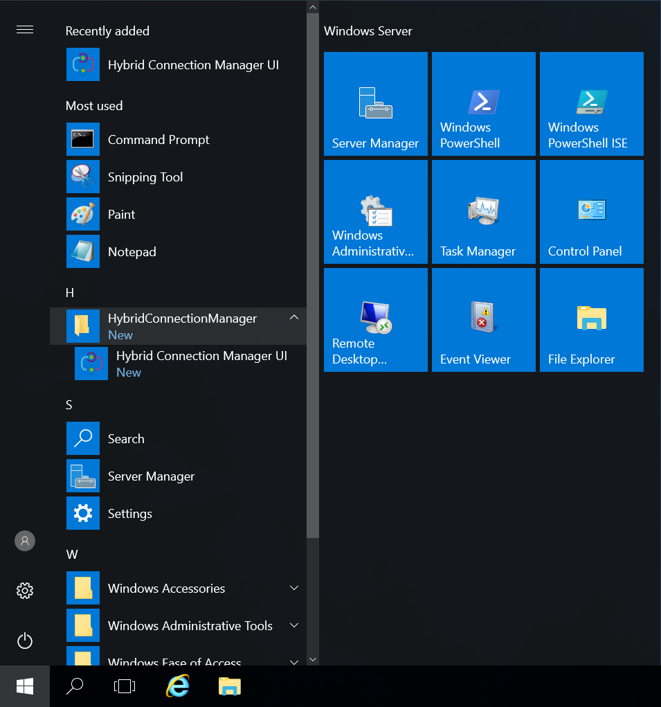
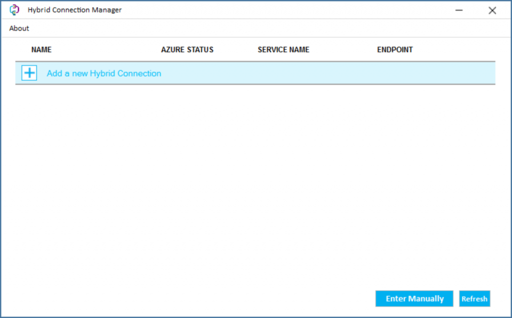
Click OK once you have filled out the information above. Once Azure has created the connection, navigate back to the machine you installed the agent on. On the machine, click Start, HybridConnectionManager, and select Hybrid Connection Manager UI.
Once the agent has launched, select Add a new Hybrid Connection.
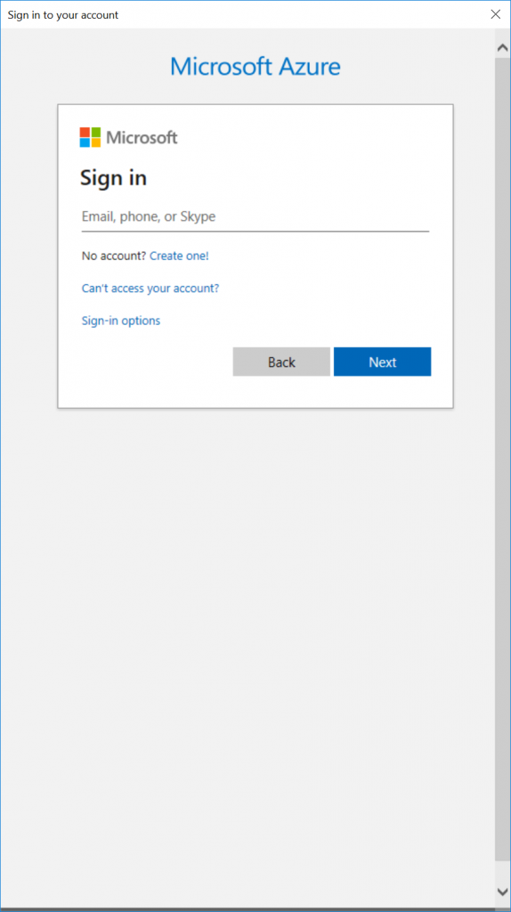
This will prompt you to enter your Azure credentials. Enter your credentials in the prompt.
Note: if the machine is locked down and cannot leverage javascript, you can close out of the sign-in window and select Enter Manually on the previous step. Back in the Azure Portal, you can select your connection and copy the "Gateway Connection String" to connect this agent to Azure.
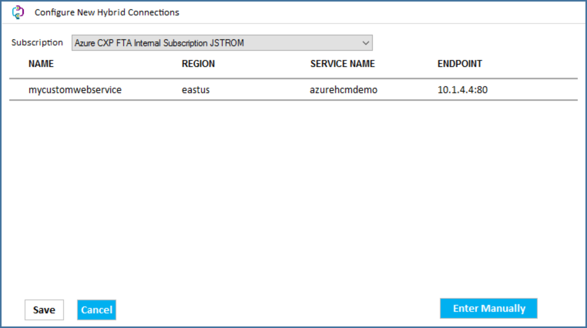
Once you have authenticated click the Subscription dropdown to select your Azure Subscription, select the connection you created via the portal, and click Save.
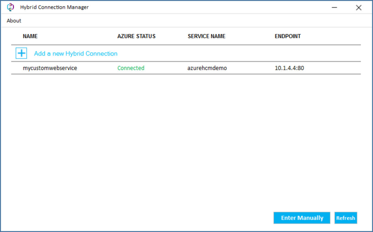
Once Saved, you should see the connection we created via the Azure Portal with the Azure Status of "Connected". If you don't see "Connected", double check you don't have a proxy blocking outbound TCP 443 requests to the Service Bus instance we created earlier (azurehcmdemo.servicebus.windows.net).
Note: To help with resiliency, you can deploy multiple agents on different machines to ensure resiliency/availability/scalability. When you select the same connection endpoint, HCM will automatically begin to load balance traffic between the agents.
Once you see the agent connected on-premises, you can validate from the Azure Portal we see the agent is connected as well. Via All services -> App Services -> your app service -> Networking -> Configure your hybrid connection endpoints, you should see "Connected" via the Status column on your Hybrid connections blade.
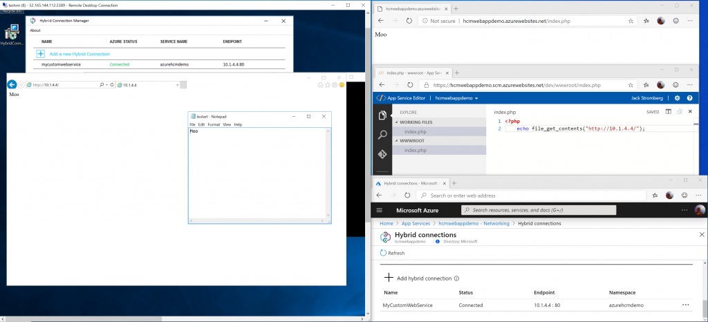
At this point, within your application, you should be able to reference the contents of the on-premises machine via the same connection string you may have used before. Below I've added an example showing an on-premises IIS server that displays the text "Moo" when you browse to the web page. Via my Web App in Azure, I created a quick PHP script that will request the on-premises server, in which HCM on the App Service will place the request on a Service Bus queue, the HCM agent on-premises will pull down the request, forward the request to the Web App on-premises, place the response back on the queue, and the web app will display the result "Moo".
Hope this helps! If you have any questions or comments feel free to reach out below.
Here is a recap of some of the reflections I have with deploying Fortinet's FortiGate appliance on Azure. This is more of a reflection of the steps I took rather than a guide, but you can use the information below as you see fit. At a high level, you will need to deploy the device on Azure and then configure the internal “guts” of the device to allow it to route traffic properly on your Virtual Network (VNet) in Azure. While Fortinet does have some documentation on deploying their appliance, I found it very confusing, so I hope this helps walk through deployment. At the time of writing this, v6.2 was the latest version; however I recommend using at least version 6.0 or greater as it provides support for auto-scaling, which is what we will be looking at for this guide.
First, just want to provide a quick overview of the different options you can take and a rough overview of each architecture:
Single FortiGate (One VM, easiest to deploy, but is not highly available)
HA FortiGate in Active/Passive mode (Two VMs with a public IP that gets manually attached to a given instance and updates to route tables)
Notes: Fortinet in active/passive deployment requires the modification of UDRs and Public IPs. Please note, any manipulation of UDRs or public IPs for Active/Passive solutions can take about 30 seconds to be applied after the failover is initiated. This deployment typically contains 4 IPs on each appliance, one used for external traffic, another for internal traffic, a third for heartbeat traffic, and a fourth for management traffic.
HA FortiGate in Active/Active mode (Two VMs load balanced by Azure Load Balancer for high availability; a little more complex to manage; sometimes called the "load balancer sandwhich")
Note: As of 8/20/2019 - the only downside to this deployment method is BYOL isn't officially supported yet (you must use Pay as you go (PAYG) licensing) and this mode will not let you easily establish VPN connections to the appliance vs Azure VPN Gateway. If using this deployment strategy, I would recommend pairing it with Azure's VPN Gateway to handle VPN connectivity.
Note: As of 8/20/2019 - I don't believe this deployment works for Azure's sovereign clouds. The image for the FortiGate appliance is only up to v6.1.0 in Azure Government Cloud and I don't see a way to specify within the FortiGate that it needs to use the Government Cloud APIs. You would need to manually modify the templates and work with Fortinet to ensure the images work for Azure's sovereign clouds. In this case, I would recommend deploying the HA FortiGate in Active/Active mode listed above.
Deploy the Appliance in Azure
As part of this tutorial, we will look at FortiGate's Autoscaling deployment as this will allow us to dynamically scale up or down depending on load. In addition, this deployment will provide us high availability, so in the event we lose a VM, network traffic will automatically failover to another appliance.
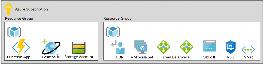
Architecture
A high level overview of what resources are deployed
Navigate to All services -> Azure Active Directory
Select App registrations
Click New Registration
Name: Fortigate-NVA
Supported account types: Accounts in this organizational directory only
Redirect URI: leave blank
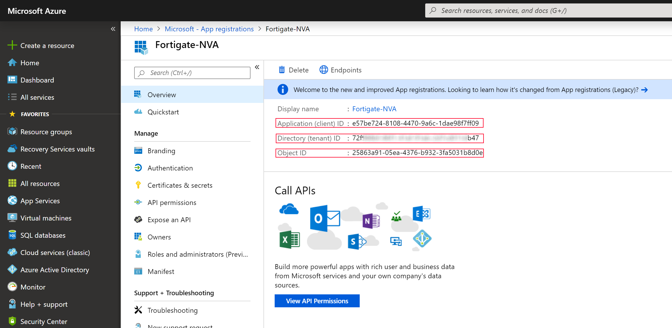
Click Register
Write down the Application (client) ID, Directory (tenant) ID, and Object ID.
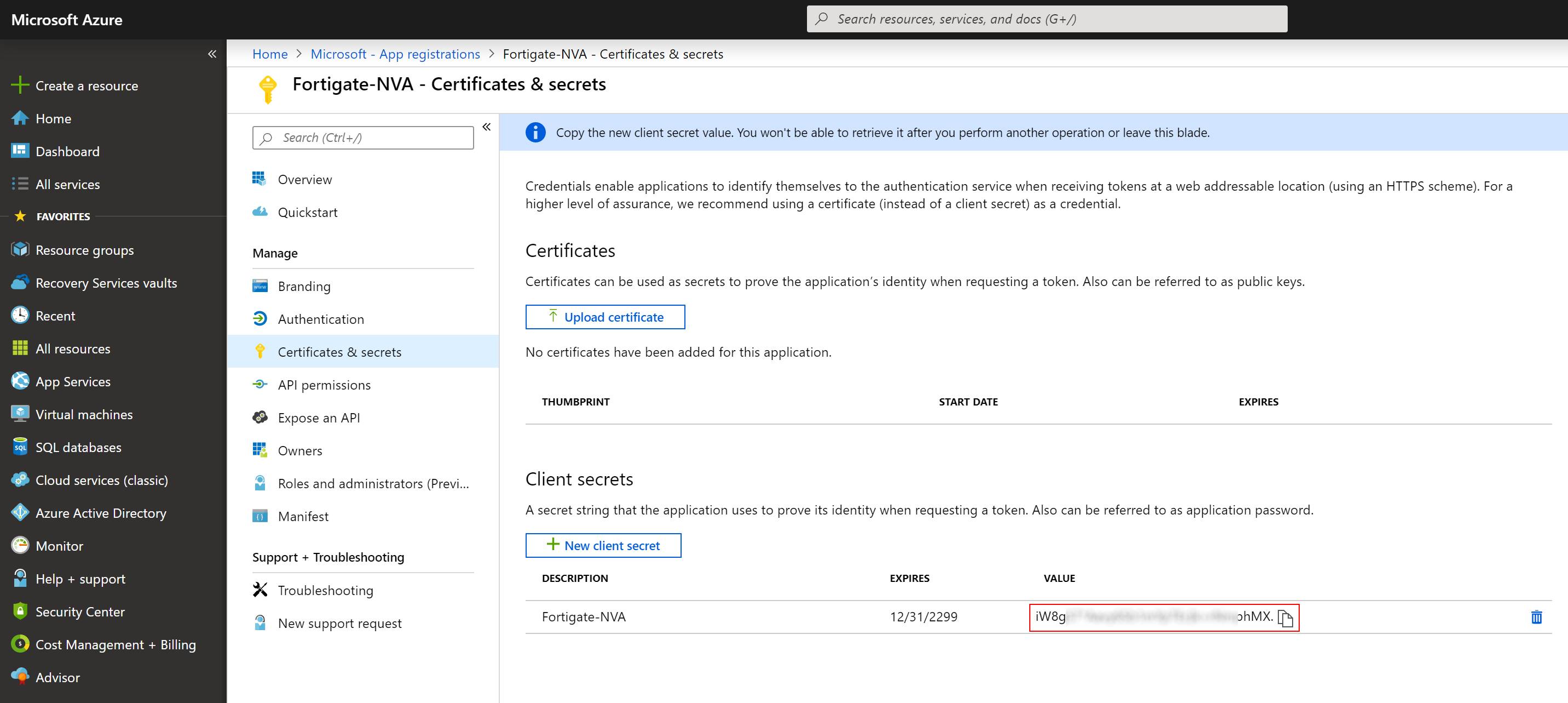
Click on Certificates & secrets
Click on the New client secret button and set the description to Fortigate-NVA, set the password expiry to your preference and click Add
Write down the value of your client secret
Note: once you navigate away from the blade you won't be able to retrieve it again
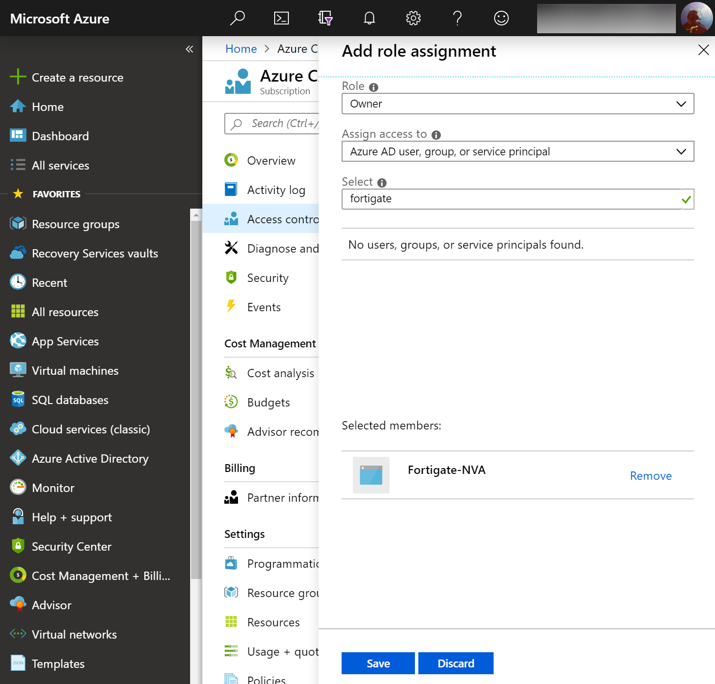
Delegate the Service Principal
Navigate to All services -> Subscriptions -> select your subscription -> and select Access control (IAM)
Click Add, Add role assignment, and use the following configuration
Role: Owner
Assign access to: Azure AD user, group, or service principal
Select: Search for Fortigate-NVA and select it
Click Save
Note: I didn't have a chance to test, but I think these permissions could likely be delegated down at the resource group level vs subscription. If someone could confirm, please leave a comment below.
Deploy the Fortigate Handler (CosmosDB and Function App)
Once you click the button above to deploy the template, use the following configuration
Function App Name
This is the name of the Azure Function resource that gets created. This must be globally unique across all customers within Azure.
Cosmos DB Name
Name of the Cosmos DB that will be created. This field must be between 3 and 31 characters and can contain only lowercase letters, numbers and -. This value should be globally unique across all customers within Azure.
Storage Account Type: Standard_LRS
Tenant ID
Use the Directory (tenant) ID from the Service Principal we created earlier.
Subscription ID
Enter the subscription ID to the Azure Subscription you wish to deploy to. You can find your subscription ID by navigating to All services -> Subscriptions and selecting your subscription.
Rest App ID
Use the Application (client) ID from the Service Principal we created earlier.
Use the value you wrote down when generating the Client Secret when creating the Service Principal.
Heart Beat Loss Count: 3
Number of consecutively lost heartbeats. When the heartbeat loss count has been reached, the VM is deemed unhealthy and failover activities commence.
Scaling Group Resource Group Name: Fortigate-VMSS-RG
This is the value of the secret Resource Group you created at the beginning of this guide. This Resource Group will contain the VM Scale Set and it's corresponding resources.
Script Timeout: 230
This is the timeout for the Function App script to run. By default this is 230 seconds.
Election Wait Time: 90
This is the maximum time (in seconds) to wait for a master election for the FortiGate's to complete.
PSK Secret: mysupersecretpassphrase
This is a random string of characters used by the FortiGates in the scale set to synchronize configuration items.
Once you click the button above to deploy the template, use the following configuration
Instance Type: Standard_F2
FOS Version: 6.2.1
VNet New Or Existing: new
Select whether you wish to use an existing or new Virtual Network
VNet Name: AzureHubVNet
The name of the VNet to be used or created.
Subnet Address Prefix: 10.0.0.0/16
The address space of the VNet to be used or created.
Subnet1Name: Untrust
The name of the subnet that will be public facing to the internet.
Subnet1Prefix: 10.0.1.0/24
The address space of the subnet to be created for the public facing zone.
Subnet2Name: Trust
The name of the subnet that will contain the private NICs of the FortiGate's.
Subnet2Prefix: 10.0.2.0/24
The address space of the subnet to be created for the private facing zone.
Subnet2Load Balancer IP: 10.0.2.10
The IP address of the load balancer in the private zone.
Subnet3Name: Private
The name of the subnet that will contain the private machines that are behind the FortiGate appliance.
Subnet3Prefix: 10.0.3.0/24
The address space of the subnet that will contain the private machines that are behind the FortiGate. Note: this is more of a place holder in FortiGate's template, you can create additional subnets later on/use a different subnet for your private resources.
Public IP New or Existing: new
The Public IP address to be associated as the VIP of the Azure Load Balancer for incoming traffic.
Scaling Group Name Prefix: fgtasg
The prefix each VMSS Name is given when deploying the FortiGate autoscale template. The value of this parameter should be the same as for deploy_funcapp.json. The prefix cannot contain special characters \/""[]:|<>+=;,?*@& or begin with '_' or end with '.' or '-'.
Initial Capacity: 2
How many FortiGate's should be deployed. Default value is 1, however I recommend at least 2 for high availability.
Min Capacity: 2
The smallest amount of FortiGate's that should be running. Default value is 1, however I recommend at least 2 for high availability.
Max Capacity: 3
The max amount of FortiGate's that should be deployed.
Scale Out Threshold: 80
Percentage of CPU utilization at which scale-out should occur.
Scale In Threshold: 20
Percentage of CPU utilization at which scale-in should occur.
Admin Username: azureadmin
FortiGate administrator username on all VMs.
Admin Password: azurepassword
FortiGate administrator password on all VMs. This field must be between 11 and 26 characters and must include at least one uppercase letter, one lowercase letter, one digit, and one special character such as (! @ # $ %).
This can be found by navigating to All services -> Function App -> YourFunctionApp-> URL on the overview blade.
At this point, your FortiGate deployment should be completed. When a FortiGate appliance comes up, it will reach out to the Azure Function to pull down its base configuration. Any changes to the primary FortiGate will be synchronized to any additional FortiGates deployed as well.
For those using a hub/spoke network, you will want to associate a UDR to each of your subnets to force traffic back to the internal load balancer's VIP. You can do this by creating a new Route Table, add a Route, set the next hop type to Virtual Appliance, and set the IP address to the IP address you specified for the "Subnet2Load Balancer IP".
You can connect to the primary FortiGate for management via web console on Port 8443 (https://IP.AD.DR.ESS:8443) or via SSH on Port 22.
Here is a recap of some of the reflections I have with deploying Cisco NGFWv (Next Generation Firewall Virtual) on Azure. This is more of a reflection of the steps I took rather than a guide, but you can use the information below as you see fit. At a high level, you will need to deploy the device on Azure and then configure the internal "guts" of the Cisco device to allow it to route traffic properly on your Virtual Network (VNet) in Azure. While Cisco does have decent documentation on deploying a single appliance, the primary purpose of this document is to look at HA/Scale out deployments.
First, just want to provide a quick overview of some of Cisco's offerings today for Azure:
Cisco CSR
In Cisco’s words:
The Cisco Cloud Services Router (CSR) 1000v is a full-featured Cisco IOS XE router, enabling IT departments to deploy enterprise-class networking services in the Microsoft Azure cloud. Most Cisco IOS XE features are also available on the virtual Cisco CSR 1000v.
Virtual MX is a virtual instance of a Meraki security & SD-WAN appliance, dedicated specifically to providing the simple configuration benefits of site-to-site Auto VPN for customers running or migrating IT services to an Amazon Web Services or Microsoft Azure Virtual Private Cloud (VPC).
The ASAv is a virtualized network security solution that provides policy enforcement and threat inspection across heterogeneous, multisite environments.
ASA firewall and VPN capabilities help safeguard traffic and multitenant architectures. Available in most hypervisor environments, the Cisco ASAv can be deployed exactly where it is needed to protect users and workloads on-premises or in the cloud.
The Cisco Firepower® NGFW (next-generation firewall) is the industry’s first fully integrated, threat-focused next-gen firewall with unified management. It uniquely provides advanced threat protection before, during, and after attacks.
The Firepower Threat Defense Virtual (FTDv) is the virtualized component of the Cisco NGFW solution. Organizations employing SDN can rapidly provision and orchestrate flexible network protection with Firepower NGFWv. As well, organizations using NFV can further lower costs utilizing Firepower FTDv.
In deploying the Cisco appliances, you'll notice you can deploy from the Azure Marketplace: https://azuremarketplace.microsoft.com/en-us/marketplace/apps/cisco.cisco-firepower-threat-defense-appliance?tab=Overview). Personally, I'm not a big fan of deploying the appliance this way as I don't have as much control over naming conventions, don't have the ability to deploy more than one appliance for scale, cannot specify my availability set, etc. While Cisco does offer an ARM template, it doesn't allow flexibility for more than two devices, nor configures anything from a load balancer perspective. In this case, I've written a custom ARM template that leverages managed disks, availability sets, consistent naming nomenclature, proper VM sizing, and most importantly, let you define how many virtual instances you'd like to deploy for scaling.
Note: this article doesn't cover deployment of Cisco's Firepower Management Center, which is what is used to centrally manage each of the scale-out instances in a "single pane of glass".
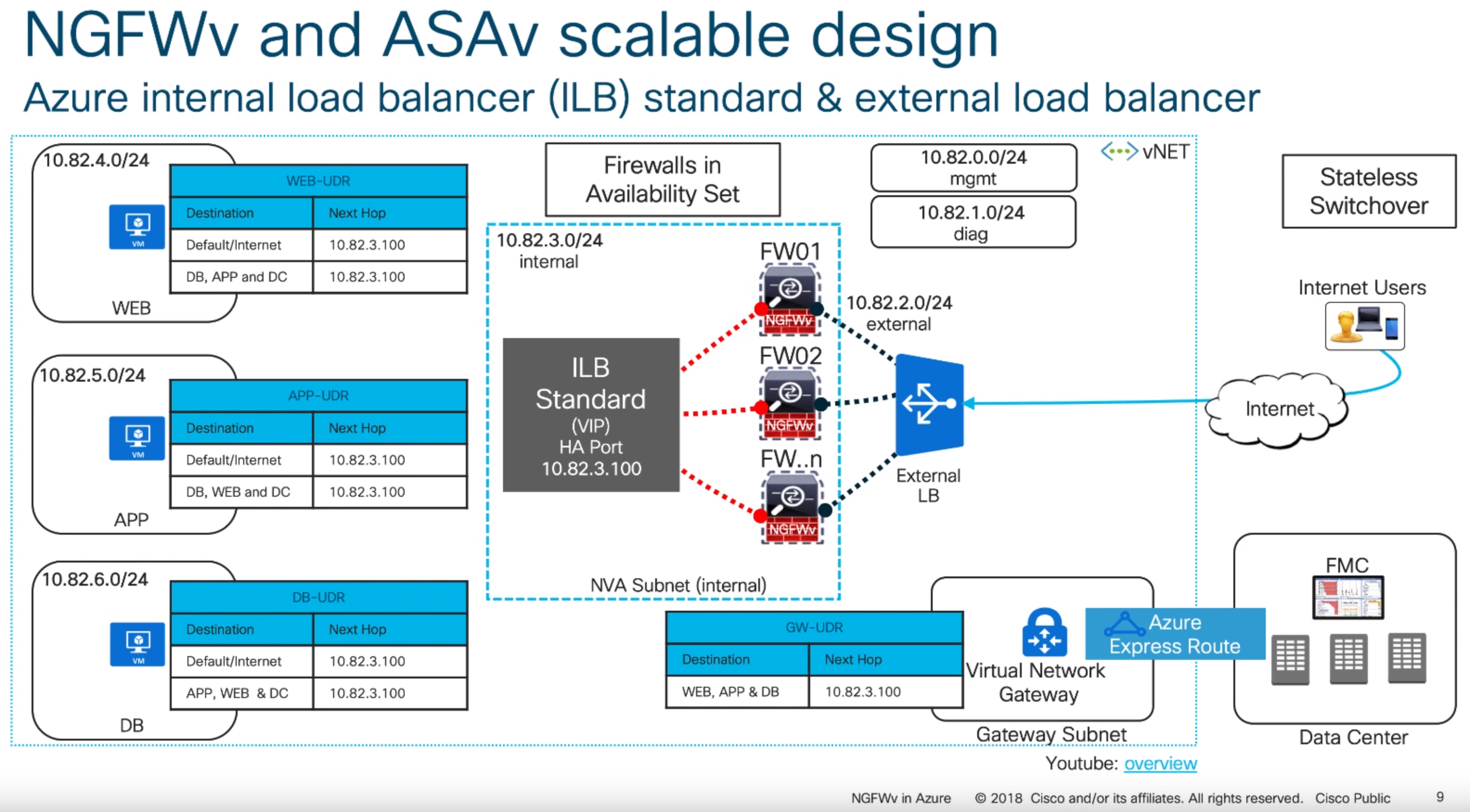
With the above said, this article will cover what Cisco calls their "scalable design" model. Here is an example of what this visually looks like (taken from one of their slide decks listed in the notes section at the bottom of this article):
Scalable design model as per Cisco's Reference Architecture
Deployment of this template can be done by navigating to the Azure Portal (portal.azure.com), select Create a resource, type Template Deployment in the Azure Marketplace, click Create, select Build your own template in the editor, and paste the code into the editor.
Alternatively, you can click this button here:
Here are some notes on what the parameters mean in the template:
VMsize: Per Cisco, the recommend VM sizes should be D3v2, D4v2, or D5v2. Interestingly, they don't call out the use of Premium storage anywhere, which I would highly recommend using if this was a single instance machine (to get at least some sort of SLA by Azure).
CiscoVersion: The version of the Cisco appliance to deploy.
CiscoCount: This defines how many virtual instances you want deployed and placed behind load balancers.
VNetName: The name of your virtual network you have created.
VNetRG: The name of the resource group your virtual network is in. This may be the same as the Resource Group you are placing the Cisco devices in, but this is a needed configurable option to prevent errors referencing a VNet in a different resource group.
envPrefix: All of the resources that get created (load balancer, virtual machines, public IPs, NICs, etc.) will use this naming nomenclature.
manPrivateIPPrefix, diagPrivateIPPrefix, trustPrivateIPPrefix, untrustPrivateIPPrefix: Corresponding subnet address range. These should be the first 3 octets of the range followed by a period. For example, 10.5.6. would be a valid value.
manPrivateIPFirst, diagPrivateIPFirst, trustPrivateIPFirst, untrustPrivateIPFirst: The first usable IP address on the subnet specified. For example, if my subnet is 10.4.255.0/24, I would need to specify 4 as my first usable address.
Username: this is the name of the privileged account that should be used to ssh and login to the PanOS web portal.
NewStorageAccountName: this is the name of the storage account that will store boot diagnostics for the Cisco appliances. This will give you the ability to see what the serial console shows. This value should be alphanumeric and 3-24 characters.
Password: Password to the privileged account used to ssh and login to the device.
Configure the Appliance
Complete these steps for both devices.
SSH to the device via it's public or private IP address of the management interface
Please note, SSH may not come up for another 10+ minutes after deployment has finished, even though the VMs show running. There are several tasks within the Cisco appliance that run post-provisioning which take awhile to complete before the ability to SSH works.
Login using the following credentials
Note: Even though we specified credentials within our template, cisco has a default set of admin credentials "baked" into the image and they should be specified during first login (which prompts you to immediately change). Please login using the default admin credentials.
Username: admin
Password: Admin123
The password is case sensitive, you should use a capital A on Admin123.
Change your password once prompted
Enter y to configure IPv4
Enter n to not configure IPv6
As of 6/1/2019, Azure only has preview support for IPv6, so this article won't cover any IPv6 specific items
Enter dhcp to configure IPv4 with DHCP
All addresses in Azure should be DHCP, static addresses are set within Azure, which essentially give the appliance a DHCP reservation
Important Note: Once you configure this option, you'll get an awkward "If your networking information has changed, you will need to reconnect" message and things will appears to be stuck. Be patient, it appears a script runs in the background, you'll see it eventually prompt for the next question.
Leave your SSH connection open for the next step
Configure NGFWv to use FirePower Management Center
Once you have gone through the initial configuration on both devices, you will need to register the sensor to a Firepower Management Center instance. To do this, you will need to run the configure manager command on both appliances. Please note I've listed the command below with the parameters it will accept, you will need to use the applicable values for your environment.
The registration key is a user-defined one-time use key that must not exceed 37 characters. Valid characters include alphanumeric characters (A–Z, a–z, 0–9) and the hyphen (-). You will need to remember this registration key when you add the device to the Firepower Management Center.
If the Firepower Management Center is not directly addressable, use DONTRESOLVE.
The NAT ID is an optional user-defined alphanumeric string that follows the same conventions as the registration key described above. It is required if the hostname is set to DONTRESOLVE. You will need to remember this NAT ID when you add the device to the Firepower Management Center
Add the appliances into FirePower Management Center
Repeat the following steps for each of the appliances you deployed
Login to FirePower Management Center
Select the Devices tab, click Device Management, and then click the Add button
If you used NAT, configure NAT and specify the NAT ID
Click Register
Initialize the interfaces on your appliances
Repeat the following steps for each of the appliances you deployed
Select the Devices tab, click Device Management, and select the edit button (Pencil Icon) for your appliance
Click the edit button (Pencil Icon) for GigabitEthernet 0/0
Name: Untrust
Check the Enabled checkbox
Security Zone: Create a new zone called Untrusted
Click the IPv4 tab
IP Type: Use Static
IP Address: IPAddressOfYourAppliance/SubnetSize
Click OK
Click the edit button (Pencil Icon) for GigabitEthernet 0/1
Name: Trust
Check the Enabled checkbox
Security Zone: Create a new zone called Trusted
Click the IPv4 tab
P Type: Use Static
IP Address: IPAddressOfYourAppliance/SubnetSize
Click OK
Click the Save button
Once you have completed the steps above, click Deploy, select each of your appliances, and click Deploy to push the configuration to the device
Configure static routes on your device
In this section, we will create several routes to handle the flow of traffic to and to/from your trusted subnets, traffic destined towards the internal, traffic destined towards the management interface (we'll need this to help handle the health probes from the azure load balancer later on), and a specific route to define the Azure Health Probes themselves.
Repeat the following steps for each of the appliances you deployed.
Select the Devices tab, click Device Management, and select the edit button (Pencil Icon) for your appliance
Select the Routing tab and click Static Route
Click the Add Route button
Type: IPv4
Interface: Trust
Create new network objects
Add network objects that represent each of the subnets you have in Azure that the device will need to return traffic to
For example, you'd repeat these steps for each private subnet
Name: DBServers
Network: 10.3.5.0/24
Click Save
Add network object for the appliance's management interface
Name: YourAppliance-mgmt
Network: IPAddressOfManagementInterface
Use the private IP of your management interface
Click Save
Add network object for Azure Health Probes
Name: Azure-LB-Probe
Network: 168.63.129.16
Click Save
Add the defined network objects above to Selected Network box
Gateway: Use the IP address of the default gateway of your subnet the Trust interface is deployed on
Note: To find this, navigate to the Azure Portal (portal.azure.com) and select All Services -> Virtual Networks -> Your Virtual Network -> Subnets and use the first IP address of your subnet the trusted interface is on. For example, if the address range of my subnet is 10.5.15.0/24, I would use 10.5.15.1 as my IP address. If my subnet was 10.5.15.128/25, I would use 129 10.5.15.129 as my IP address
Metric: 3
Click OK
Click the Add Route button
Type: IPv4
Interface: Untrust
Add the any-ipv4 object to Selected Network box
This will allow us to force all internet bound traffic through our Untrust interface
Add the Azure-LB-Probe object to the Selected Network box
This will allow health probes from the external azure load balancer probes to flow properly
Add the YourAppliance-mgmt object to the Selected Network box
Gateway: Use the IP address of the default gateway of your subnet the Untrust interface is deployed on
Note: To find this, navigate to the Azure Portal (portal.azure.com) and select All Services -> Virtual Networks -> Your Virtual Network -> Subnets and use the first IP address of your subnet the untrusted interface is on. For example, is the address range of my subnet is 10.5.15.0/24, I would use 10.5.15.1 as my IP address. If my subnet was 10.5.15.128/25, I would use 129 10.5.15.129 as my IP address
Metric: 2
Click OK
Click the Save button
Once you have completed the steps above, click Deploy, select each of your appliances, and click Deploy to push the configuration to the device
Configure NAT Policies
First create a NAT rule that will SNAT any traffic from our trusted zone to the Untrust interface. This is needed so Azure understands to return traffic through the external interface of your device for inspection.
Select the Devices tab, click NAT, and select the Threat Defense NAT Policy link (or New Policy button)
Select your first appliance, click the Add to Policy button, and click Save
Click the Add Rule button
NAT Rule: Auto NAT Rule
Type: Dynamic
Interface Objects Tab
Select the Trusted Interface Object and click the Add to Source button
Select the Untrusted Interface object and click the Add to Destination button
Translation Tab
Click the green button to add a new network object under Original Packet
Name: any-ipv4
Network: 0.0.0.0/0
Click Save
Original Source: any-ipv4
Translated Source: Destination Interface IP
Click OK
Next, we need to create a new NAT statement to handle traffic for our load balancer probes. We will need to configure two statements since we will receive health probes from the same IP address (168.63.129.16) to both NICs. On the same appliance, continue the following steps.
Click the Add Rule button
NAT Rule: Manual NAT Rule
Type: Static
Interface Objects Tab
Select the Trusted Interface Object and click the Add to Source button
Select the Untrusted Interface object and click the Add to Destination button
Translation Tab
Original Source: Azure-LB-Probe
Original Destination: Source Interface IP
Original Destination Port: SSH
Translated Source: Destination Interface IP
Translated Destination: YourAppliance-mgmt
Translated Destination Port: SSH
Click OK
Click the Add Rule button
NAT Rule: Manual NAT Rule
Type: Static
Interface Objects Tab
Select the Untrusted Interface Object and click the Add to Source button
Select the Trusted Interface object and click the Add to Destination button
Translation Tab
Original Source: Azure-LB-Probe
Original Destination: Source Interface IP
Original Destination Port: SSH
Translated Source: Destination Interface IP
Translated Destination: YourAppliance-mgmt
Translated Destination Port: SSH
Click OK
Optional Step: If you are using the appliances to front applications to the internet, you will also need to configure a NAT rule for ingress traffic. This is an optional step, but will show you how to configure traffic to let's say a web server (which the ALB is configured to listen for per the template). If you do complete this step, make sure you add an access policy (Policies -> Access Control -> Select your policy -> click Add Rule).
Click the Add Rule button
NAT Rule: Manual NAT Rule
Type: Static
Interface Objects Tab
Select the Untrusted Interface Object and click the Add to Source button
Select the Trusted Interface object and click the Add to Destination button
Translation Tab
Original Source: any-ipv4
Original Destination: Source Interface IP
Original Destination Port: HTTP
Translated Source: Destination Interface IP
Translated Destination: webserver
Click the green add button to create a new network object to define the private IP address of your web server.
Translated Destination Port: HTTP
Click OK
Click Save once you have finished adding the rules.
At this point, you will need to repeat the same steps above. The reason why we cannot apply the policy to both devices is when you configure the rule for the Azure Health Probes, you'll need to specify the correct Translated Destination (I.e. Appliance1 should use the network object that resolves to appliance 1; Appliance2 should use the network object that resolves to appliance 2)
Once you have completed the steps above, click Deploy, select each of your appliances, and click Deploy to push the configuration to the device
Finalize the environment
Now that the environment is configured, there are two steps you will want to check back on.
Add Route Tables to each subnet to force traffic to the Cisco appliances
Remove the public IP from your management interface
Considering at this point you've configured the device and have private connectivity via VPN or ExpressRoute, I'd remove the public IP from your management interface to prevent the public internet from accessing this interface
Adjust NSG rules
Similar to above, I'd scope down who/what network segments can pass traffic to the device. Go back and modify the NSG on the management interfaces to only allow traffic from specific source addresses.
Here is a recap of some of the reflections I have with deploying Palo Alto's VM-Series Virtual Appliance on Azure. This is more of a reflection of the steps I took rather than a guide, but you can use the information below as you see fit. At a high level, you will need to deploy the device on Azure and then configure the internal "guts" of the Palo Alto to allow it to route traffic properly on your Virtual Network (VNet) in Azure. The steps outlined should work for both the 8.0 and 8.1 versions of the Palo Alto VM-Series appliance.
Please note, this tutorial also assumes you are looking to deploy a scale-out architecture. This can help ensure a single instance doesn't get overwhelmed with the amount of bandwidth you are trying to push through it. If you are looking for a single instance, you can still follow along.
Deploy the Appliance in Azure
In deploying the Virtual Palo Altos, the documentation recommends to create them via the Azure Marketplace (which can be found here: https://azuremarketplace.microsoft.com/en-us/marketplace/apps/paloaltonetworks.vmseries-ngfw?tab=Overview). Personally, I'm not a big fan of deploying the appliance this way as I don't have as much control over naming conventions, don't have the ability to deploy more than one appliance for scale, cannot specify my availability set, cannot leverage managed disks, etc. In addition, I noticed a really strange error that if you specify a password greater than 31 characters, the Palo Alto devices flat out won't deploy on Azure. In this case, I've written a custom ARM template that leverages managed disks, availability sets, consistent naming nomenclature, proper VM sizing, and most importantly, let you define how many virtual instances you'd like to deploy for scaling.
Note: this article doesn't cover the concept of using Panorama, but that would centrally manage each of the scale-out instances in a "single pane of glass". Below, we will cover setting up a node manually to get it working. It is possible to create a base-line configuration file that joins Panorama post-deployment to bootstrap the nodes upon deployment of the ARM template. The bootstrap file is not something I've incorporated into this template, but the template could easily be modified to do so.
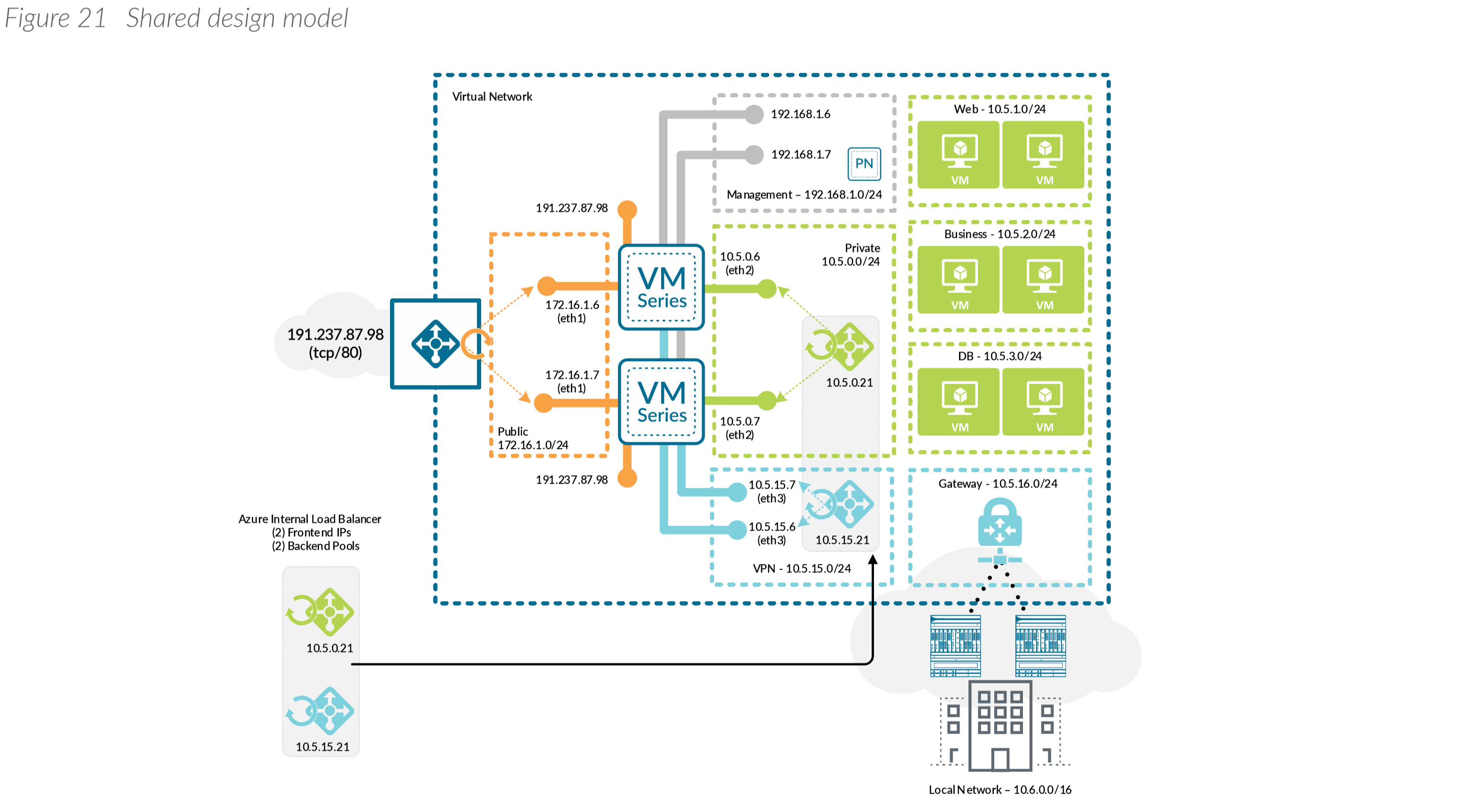
With the above said, this article will cover what Palo Alto considers their Shared design model. Here is an example of what this visually looks like (taken from Palo Alto's Reference Architecture document listed in the notes section at the bottom of this article):
Shared design model as per Palo Alto's Reference Architecture
Deployment of this template can be done by navigating to the Azure Portal (portal.azure.com), select Create a resource, type Template Deployment in the Azure Marketplace, click Create, select Build your own template in the editor, and paste the code into the editor.
Alternatively, you can click this button here:
Here are some notes on what the parameters mean in the template:
VMsize: Per Palo Alto, the recommend VM sizes should be DS3, DS4, or DS5. Documentation on this can be found here.
PACount: This defines how many virtual instances you want deployed and placed behind load balancers.
VNetName: The name of your virtual network you have created.
VNetRG: The name of the resource group your virtual network is in. This may be the same as the Resource Group you are placing the Palos in, but this is a needed configurable option to prevent errors referencing a VNet in a different resource group.
envPrefix: All of the resources that get created (load balancer, virtual machines, public IPs, NICs, etc.) will use this naming nomenclature.
manPrivateIPPrefix, trustPrivateIPPrefix, untrustPrivateIPPrefix: Corresponding subnet address range. These should be the first 3 octets of the range followed by a period. For example, 10.5.6. would be a valid value.
manPrivateIPFirst, trustPrivateIPFirst, untrustPrivateIPFirst: The first usable IP address on the subnet specified. For example, if my subnet is 10.4.255.0/24, I would need to specify 4 as my first usable address.
Username: this is the name of the privileged account that should be used to ssh and login to the PanOS web portal.
Password: Password to the privileged account used to ssh and login to the PanOS web portal. Must be 31 characters or less due to Pan OS limitation.
Configure the Appliance
Once the virtual appliance has been deployed, we need to configure the Palo Alto device itself to enable connectivity on our Trust/Untrust interfaces.
On the firewall web interface, select Device tab -> Licenses and select Activate feature using authentication code.
Enter the capacity auth-code that you registered on the support portal. The firewall will connect to the update server (updates.paloaltonetworks.com), and download the license and reboot automatically. If this doesn't work, please continue below to configuring the interfaces of the device.
Log back in to the web interface after reboot and confirm the following on the Dashboard:
A valid serial number displays in Serial#. If the term Unknown displays, it means the device is not licensed. To view traffic logs on the firewall, you must install a valid capacity license.
The VM Mode displays as Microsoft Azure.
Follow these steps if using the PAYG (Pay as you go) version
Select Network-> Interfaces ->Ethernet-> select the link for ethernet1/1 and configure as follows:
Interface Type: Layer3 (default).
On the Config tab, assign the interface to the Untrust-VR router.
On the Config tab, expand the Security Zone drop-down and select New Zone. Define a new zone called Untrust, and then click OK.
On the IPv4 tab, select DHCP Client if you plan to assign only one IP address on the interface. If you plan to assign more than one IP address select Static and manually enter the primary and secondary IP addresses assigned to the interface on the Azure portal. The private IP address of the interface can be found by navigating to Virtual Machines -> YOURPALOMACHINE -> Networking and using the Private IP address specified on each tab.
Note: Do not use the Public IP address to the Virtual Machine. Azure automatically DNATs traffic to your private address so you will need to use the Private IP Address for your UnTrust interface.
Clear the Automatically create default route to default gateway provided by server check box.
Note: Disabling this option ensures that traffic handled by this interface does not flow directly to the default gateway in the VNet.
Click OK
Note: For the untrust interface, within your Azure environment ensure you have a NSG associated to the untrust subnet or individual firewall interfaces as the template doesn't deploy this for you (I could add this in, but if you already had an NSG I don't want to overwrite it). As per Azure Load Balancer's documentation, you will need an NSG associated to the NICs or subnet to allow traffic in from the internet.
Configure the Trust Interface
Select Network-> Interfaces ->Ethernet-> select the link for ethernet1/2 and configure as follows:
Interface Type: Layer3 (default).
On the Config tab, assign the interface to the Trust-VR router.
On the Config tab, expand the Security Zone drop-down and select New Zone. Define a new zone called Trust, and then click OK.
On the IPv4 tab, select DHCP Client if you plan to assign only one IP address on the interface. If you plan to assign more than one IP address select Static and manually enter the primary and secondary IP addresses assigned to the interface on the Azure portal. The private IP address of the interface can be found by navigating to Virtual Machines -> YOURPALOMACHINE-> Networking and using the Private IP address specified on each tab.
Clear the Automatically create default route to default gateway provided by server check box.
Note: Disabling this option ensures that traffic handled by this interface does not flow directly to the default gateway in the VNet.
Click OK
Click Commit in the top right. Verify that the link state for the interfaces is up (the interfaces should turn green in the Palo Alto user interface).
Define Static Routes
The Palo Alto will need to understand how to route traffic to the internet and how to route traffic to your subnets. As you will see in this section, we will need two separate virtual routers to help handle the processing of health probes submitted from each of the Azure Load Balancers.
Create a new Virtual Router and Static Route to the internet
Select Network -> Virtual Router
Click Add at the bottom
Set the Name to Untrust-VR
Select Static Routes -> IPv4 -> Add
Create a Static Route to egress internet traffic
Name: Internet
Destination: 0.0.0.0/0
Interface: ethernet 1/1
Next Hop: IP Address
IP Address: Use the IP address of the default gateway of your subnet the Untrust interface is deployed on
Note: To find this, navigate to the Azure Portal (portal.azure.com) and select All Services -> Virtual Networks -> Your Virtual Network -> Subnets and use the first IP address of your subnet the untrust interface is on. For example, is the address range of my subnet is 10.5.15.0/24, I would use 10.5.15.1 as my IP address. If my subnet was 10.5.15.128/25, I would use 129 10.5.15.129 as my IP address
Create a Static Route to move traffic from the internet to your trusted VR
Name: Internal Routes
Destination: your vnet address space
Interface: None
Next Hop: Next VR
Trust-VR
Click OK
Create a new Virtual Router and Static Route to your Azure Subnets
Select Network -> Virtual Router
Click Add at the bottom
Set the Name to Trust-VR
Select Static Routes -> IPv4 -> Add
Create a Static Route to send traffic to Azure from your Trusted interface
Name: AzureVNet
Destination: your vnet address space
Interface: ethernet 1/2
Next Hop: IP Address
IP Address: Use the IP address of the default gateway of your subnet the Trust interface is deployed on
Note: To find this, navigate to the Azure Portal (portal.azure.com) and select All Services -> Virtual Networks -> Your Virtual Network -> Subnets and use the first IP address of your subnet the trust interface is on. For example, if the address range of my subnet is 10.5.15.0/24, I would use 10.5.15.1 as my IP address. If my subnet was 10.5.15.128/25, I would use 129 10.5.15.129 as my IP address
Create a Static Route to move internet traffic received on Trust to your Untrust Virtual Router
Name: Internet
Destination: 0.0.0.0/0
Interface: None
Next Hop: Next VR
Untrust-VR
Click OK
Click Commit in the top right.
Configure Health Probes for Azure Load Balancers
If deploying the Scale-Out scenario, you will need to approve TCP probes from 168.63.129.16, which is the IP address of the Azure Load Balancer. Azure health probes come from a specific IP address (168.63.129.16). In this case, we need a static route to allow the response back to the load balancer. For the purpose of this article, we will configure SSH on the Trust interface strictly for the Azure Load Balancer to contact to validate the Palo Alto instances are healthy.
Configure Palo Alto SSH Service for the interfaces
First we need to create an Interface Management Profile
Next, we need to assign the profile to the Trust interface
Select Network -> Interfaces ->select the link for ethernet1/2
Select the Advanced tab
Set the Management Profile to SSH-MP
Click OK
Next, we need to assign the profile to the Untrust interface
Select Network -> Interfaces ->select the link for ethernet1/1
Select the Advanced tab
Set the Management Profile to SSH-MP
Click OK
Create a Static Route for the Azure Load Balancer Health Probes on the Untrust Interface
Next we need to tell the health probes to flow out of the Untrust interface due to our 0.0.0.0/0 rule.
Select Network -> Virtual Router -> Untrust-VR
Select Static Routes -> IPv4 -> Add
Use the following configuration
Name: AzureLBHealthProbe
Destination: 168.63.129.16/32
Interface: ethernet 1/1
Next Hop: IP Address
IP Address: Use the IP address of the default gateway of your subnet the Trust interface is deployed on
Note: To find this, navigate to the Azure Portal (portal.azure.com) and select All Services -> Virtual Networks -> Your Virtual Network -> Subnets and use the first IP address of your subnet the trust interface is on. For example, if the address range of my subnet is 10.5.15.0/24, I would use 10.5.15.1 as my IP address. If my subnet was 10.5.15.128/25, I would use 129 10.5.15.129 as my IP address
Click OK
Create a Static Route for the Azure Load Balancer Health Probes on the Trust Interface
Next we need to tell the health probes to flow out of the Trust interface due to our 0.0.0.0/0 rule.
Select Network -> Virtual Router -> Trust-VR
Select Static Routes -> IPv4 -> Add
Use the following configuration
Name: AzureLBHealthProbe
Destination: 168.63.129.16/32
Interface: ethernet 1/2
Next Hop: IP Address
IP Address: Use the IP address of the default gateway of your subnet the Trust interface is deployed on
Note: To find this, navigate to the Azure Portal (portal.azure.com) and select All Services -> Virtual Networks -> Your Virtual Network -> Subnets and use the first IP address of your subnet the trust interface is on. For example, if the address range of my subnet is 10.5.15.0/24, I would use 10.5.15.1 as my IP address. If my subnet was 10.5.15.128/25, I would use 129 10.5.15.129 as my IP address
Click OK
Click Commit in the top right.
Create a NAT rule for internal traffic destined to the internet
You will need to NAT all egress traffic destined to the internet via the address of the Untrust interface, so return traffic from the Internet comes back through the Untrust interface of the device.
Navigate to Policies -> NAT
Click Add
On the General tab use the following configuration
Name: UntrustToInternet
Description: Rule to NAT all trusted traffic destined to the Internet to the Untrust interface
On the Original Packet tab use the following configuration
Source Zone: Click Add and select Trust
Destination Zone: Untrust
Destination Interface: ethernet 1/1
Service: Check Any
Source Address: Click Add, use the Internal Address space of your Trust zones
Destination address: Check Any
On the TranslatedPacket tab use the following configuration
By default, Palo Alto deploys 8.0.0 for the 8.0.X series and 8.1.0 for the 8.1.X series. In this case, Palo Alto will strongly recommend you upgrade the appliance to the latest version of that series before helping you with support cases.
To do this, go to Device -> Dynamic Updates -> click Check Now in the bottom left and download the latest build from the list of available updates.
Please note: the update process will require a reboot of the device and can take 20 minutes or so.
Summary
At this point you should have a working scaled out Palo Alto deployment. If all went well, I would recommend removing the public IP to the management interface or at least scoping it down to the single public IP address you are coming from. You can find your public IP address by navigating here: https://jackstromberg.com/whats-my-ip-address/
TLDR: There are two sections of this article; feel free to scroll down to the titles for the applicable section.
Using VM Extensions with Terraform to Domain Join Virtual Machines
VM Extensions are a fantastic way to yield post deployment configurations via template as code in Azure. One of Azure's most common VM Extensions is the JoinADDomainExtension, which will join your Azure VM to an Active Directory machine after the machine has successfully been provisioned. For the purposes of this artcicle, we will assume you have a VM called testvm in the East US region.
Typically, VM extensions can be configured via the following block of ARM Template code (a fully working example building the virtual and running the extension can be found here).
When looking at Terraform, the syntax is a bit different and there isn't much documentation on how to handle the settings and most importantly, the password/secret used when joining the machine to the domain. In this case, here is working translation of the ARM template to Terraform.
The key pieces here are the SETTINGS and PROTECTED_SETTINGS blocks that allow you to pass the traditional JSON attributes as you would in the ARM template. Luckily, terraform does a somewhat decent job documentation this on their public docs here, so if you have any additional questions on any of the attributes you can find them all here: https://www.terraform.io/docs/providers/azurerm/r/virtual_machine_extension.html
The last block of code I have specified at the very end is a depends_on statement. This simpy ensures that this resource is not created until the Virtual Machine itself has successfully been provisioned and can be very beneficial if you have other scripts that may need to run prior to domain join.
Using VM Extensions with Terraform to customize a machine post deployment
Continuing along the lines of customizing a virtual machine post deployment, Azure has a handy dandy extension called CustomScriptExtension. What this extension does is allow you to arbitrarily download and execute files (typically PowerShell) after a virtual machine has been deployed. Unlike the domain join example above, Azure has extensive documentation on this extension and provides support for both Windows and Linux (click the links for Windows or Linux to see the Azure docs on this).
Following similar suite as the above Domain Join example, within the ARM world, we can leverage the following template to execute code post deployment:
When we look at the translation over to Terraform, for the most part the structure is the exact same. Similar to our Active Directory Domain Join script above, the tricky piece is knowing to use the PROTECTED_SETTINGS to encapsulate our block of code that in this case authenticates to the Azure Storage Account to pull down our post-deployment script. Now per the Azure documentation, those variables are optional; if the scripts you have don't contain sensitive information, you are more than welcome to simply specify the fileUri and specify the commandToExecute via the regular SETTINGS block.
At this point you should be able to leverage both extensions to join a machine to the domain and then customize virtually any aspect of the machine thereafter.
The only thing I'll leave you with is typically it is recommended to not leave clear-text passwords scattered through your templates. In either case, I highly recommend looking at leveraging Azure Key Vault or an alternative solution that can ensure proper security in handling those secrets.
Notes
Aside from Terraform, one question I've received is what happens if the extension runs against a machine that is already domain joined? A: The VM extension will still install against the Azure Virtual Machine, but will immediately return back the following response: "Join completed for Domain 'yourdomain.com'"
Specifically, the following is returned back to Azure: [{"version":"1","timestampUTC":"2019-03-27T16:30:57.9274393Z","status":{"name":"ADDomainExtension","operation":"Join Domain/Workgroup","status":"success","code":0,"formattedMessage":{"lang":"en-US","message":"Join completed for Domain 'yourdomain.com'"},"substatus":null}}]
What does Options mean for domain join?
A: Copied from here: The options are a set of bit flags that define the join options. Default value of 3 is a combination of NETSETUP_JOIN_DOMAIN (0x00000001) & NETSETUP_ACCT_CREATE (0x00000002) i.e. will join the domain and create the account on the domain. For more information see https://msdn.microsoft.com/en-us/library/aa392154(v=vs.85).aspx
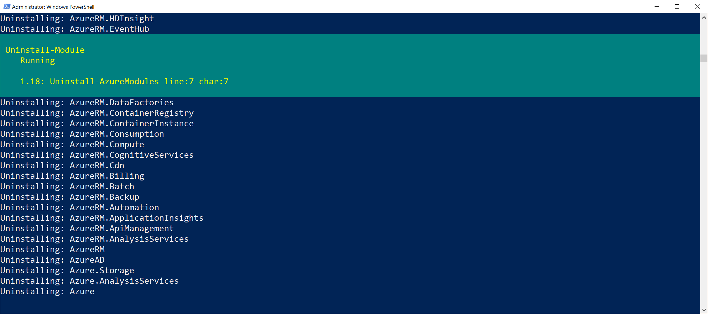
With Azure PowerShell modules changing all the time and the recent introduction of the PowerShell modules being renamed from AzureRm to Az, you may want to totally uninstall all modules and reinstall to make sure you are using the latest and greatest modules.
To do so, StackOverflow user BlueSky, wrote a handy dandy script that will go through and cleanup all the Azure(RM)(AD) modules. Simply open up PowerShell as an Administrator and execute the following PowerShell workflow/commands:
The thing about the PowerShell script above being a workflow is this allows you to remove all the modules in parallel vs one-by-one. Here's a screenshot of the script in action.
Per Microsoft: Some packages may not install using pip when run on Azure. It may simply be that the package is not available on the Python Package Index. It could be that a compiler is required (a compiler is not available on the machine running the web app in Azure App Service).
Example, you may receive an error like this when trying to install a specific package (in this case, trying to install Pandas):
Command: "D:\home\site\deployments\tools\deploy.cmd"
Handling python deployment.
KuduSync.NET from: 'D:\home\site\repository' to: 'D:\home\site\wwwroot'
Copying file: 'requirements.txt'
Detected requirements.txt. You can skip Python specific steps with a .skipPythonDeployment file.
Detecting Python runtime from runtime.txt
Detected python-2.7Found compatible virtual environment.Pip install requirements.Downloading/unpacking Flask==0.12.1 (from -r requirements.txt (line 1))Downloading/unpacking numpy==1.15.0rc2 (from -r requirements.txt (line 2))Downloading/unpacking pandas==0.22.0 (from -r requirements.txt (line 3)) Running setup.py (path:D:\home\site\wwwroot\env\build\pandas\setup.py) egg_info for package pandas Could not locate executable g77
Could not locate executable f77
Could not locate executable ifort
Could not locate executable ifl
Could not locate executable f90
Could not locate executable efl
Could not locate executable gfortran
Could not locate executable f95
Could not locate executable g95
Could not locate executable effort
Could not locate executable efc
don't know how to compile Fortran code on platform 'nt'
non-existing path in 'numpy\\distutils': 'site.cfg'
Running from numpy source directory. d:\local\temp\easy_install-dsrz9g\numpy-1.15.0rc2\setup.py:385: UserWarning: Unrecognized setuptools command, proceeding with generating Cython sources and expanding templates run_build = parse_setuppy_commands() D:\python27\Lib\distutils\dist.py:267: UserWarning: Unknown distribution option: 'python_requires' warnings.warn(msg) d:\local\temp\easy_install-dsrz9g\numpy-1.15.0rc2\numpy\distutils\system_info.py:625: UserWarning: Atlas (http://math-atlas.sourceforge.net/) libraries not found. Directories to search for the libraries can be specified in the numpy/distutils/site.cfg file (section [atlas]) or by setting the ATLAS environment variable. self.calc_info() d:\local\temp\easy_install-dsrz9g\numpy-1.15.0rc2\numpy\distutils\system_info.py:625: UserWarning: Blas (http://www.netlib.org/blas/) libraries not found. Directories to search for the libraries can be specified in the numpy/distutils/site.cfg file (section [blas]) or by setting the BLAS environment variable. self.calc_info() d:\local\temp\easy_install-dsrz9g\numpy-1.15.0rc2\numpy\distutils\system_info.py:625: UserWarning: Blas (http://www.netlib.org/blas/) sources not found. Directories to search for the sources can be specified in the numpy/distutils/site.cfg file (section [blas_src]) or by setting the BLAS_SRC environment variable. self.calc_info() d:\local\temp\easy_install-dsrz9g\numpy-1.15.0rc2\numpy\distutils\system_info.py:625: UserWarning: Lapack (http://www.netlib.org/lapack/) libraries not found. Directories to search for the libraries can be specified in the numpy/distutils/site.cfg file (section [lapack]) or by setting the LAPACK environment variable. self.calc_info() d:\local\temp\easy_install-dsrz9g\numpy-1.15.0rc2\numpy\distutils\system_info.py:625: UserWarning: Lapack (http://www.netlib.org/lapack/) sources not found. Directories to search for the sources can be specified in the numpy/distutils/site.cfg file (section [lapack_src]) or by setting the LAPACK_SRC environment variable. self.calc_info() D:\python27\Lib\distutils\dist.py:267: UserWarning: Unknown distribution option: 'define_macros' warnings.warn(msg) Traceback (most recent call last): File "<string>", line 17, in <module> File "D:\home\site\wwwroot\env\build\pandas\setup.py", line 743, in <module> **setuptools_kwargs) File "D:\python27\Lib\distutils\core.py", line 111, in setup _setup_distribution = dist = klass(attrs) File "D:\home\site\wwwroot\env\lib\site-packages\setuptools\dist.py", line 262, in __init__ self.fetch_build_eggs(attrs['setup_requires']) File "D:\home\site\wwwroot\env\lib\site-packages\setuptools\dist.py", line 287, in fetch_build_eggs replace_conflicting=True, File "D:\home\site\wwwroot\env\lib\site-packages\pkg_resources.py", line 614, in resolve dist = best[req.key] = env.best_match(req, ws, installer) File "D:\home\site\wwwroot\env\lib\site-packages\pkg_resources.py", line 857, in best_match return self.obtain(req, installer) File "D:\home\site\wwwroot\env\lib\site-packages\pkg_resources.py", line 869, in obtain return installer(requirement) File "D:\home\site\wwwroot\env\lib\site-packages\setuptools\dist.py", line 338, in fetch_build_egg return cmd.easy_install(req) File "D:\home\site\wwwroot\env\lib\site-packages\setuptools\command\easy_install.py", line 613, in easy_install return self.install_item(spec, dist.location, tmpdir, deps) File "D:\home\site\wwwroot\env\lib\site-packages\setuptools\command\easy_install.py", line 643, in install_item dists = self.install_eggs(spec, download, tmpdir) File "D:\home\site\wwwroot\env\lib\site-packages\setuptools\command\easy_install.py", line 833, in install_eggs return self.build_and_install(setup_script, setup_base) File "D:\home\site\wwwroot\env\lib\site-packages\setuptools\command\easy_install.py", line 1055, in build_and_install self.run_setup(setup_script, setup_base, args) File "D:\home\site\wwwroot\env\lib\site-packages\setuptools\command\easy_install.py", line 1043, in run_setup raise DistutilsError("Setup script exited with %s" % (v.args[0],)) distutils.errors.DistutilsError: Setup script exited with error: Microsoft Visual C++ 9.0 is required (Unable to find vcvarsall.bat). Get it from http://aka.ms/vcpython27 Complete output from command python setup.py egg_info:Could not locate executable g77
Could not locate executable f77
Could not locate executable ifort
Could not locate executable ifl
Could not locate executable f90
Could not locate executable efl
Could not locate executable gfortran
Could not locate executable f95
Could not locate executable g95
Could not locate executable effort
Could not locate executable efcdon't know how to compile Fortran code on platform 'nt'non-existing path in 'numpy\\distutils': 'site.cfg'Running from numpy source directory.d:\local\temp\easy_install-dsrz9g\numpy-1.15.0rc2\setup.py:385: UserWarning: Unrecognized setuptools command, proceeding with generating Cython sources and expanding templates run_build = parse_setuppy_commands()D:\python27\Lib\distutils\dist.py:267: UserWarning: Unknown distribution option: 'python_requires' warnings.warn(msg)
d:\local\temp\easy_install-dsrz9g\numpy-1.15.0rc2\numpy\distutils\system_info.py:625: UserWarning: Atlas (http://math-atlas.sourceforge.net/) libraries not found. Directories to search for the libraries can be specified in the numpy/distutils/site.cfg file (section [atlas]) or by setting the ATLAS environment variable. self.calc_info()d:\local\temp\easy_install-dsrz9g\numpy-1.15.0rc2\numpy\distutils\system_info.py:625: UserWarning: Blas (http://www.netlib.org/blas/) libraries not found. Directories to search for the libraries can be specified in the numpy/distutils/site.cfg file (section [blas]) or by setting the BLAS environment variable. self.calc_info()d:\local\temp\easy_install-dsrz9g\numpy-1.15.0rc2\numpy\distutils\system_info.py:625: UserWarning: Blas (http://www.netlib.org/blas/) sources not found. Directories to search for the sources can be specified in the numpy/distutils/site.cfg file (section [blas_src]) or by setting the BLAS_SRC environment variable. self.calc_info()d:\local\temp\easy_install-dsrz9g\numpy-1.15.0rc2\numpy\distutils\system_info.py:625: UserWarning: Lapack (http://www.netlib.org/lapack/) libraries not found. Directories to search for the libraries can be specified in the numpy/distutils/site.cfg file (section [lapack]) or by setting the LAPACK environment variable. self.calc_info()d:\local\temp\easy_install-dsrz9g\numpy-1.15.0rc2\numpy\distutils\system_info.py:625: UserWarning: Lapack (http://www.netlib.org/lapack/) sources not found. Directories to search for the sources can be specified in the numpy/distutils/site.cfg file (section [lapack_src]) or by setting the LAPACK_SRC environment variable. self.calc_info()D:\python27\Lib\distutils\dist.py:267: UserWarning: Unknown distribution option: 'define_macros' warnings.warn(msg)Traceback (most recent call last): File "<string>", line 17, in <module> File "D:\home\site\wwwroot\env\build\pandas\setup.py", line 743, in <module> **setuptools_kwargs) File "D:\python27\Lib\distutils\core.py", line 111, in setup _setup_distribution = dist = klass(attrs) File "D:\home\site\wwwroot\env\lib\site-packages\setuptools\dist.py", line 262, in __init__ self.fetch_build_eggs(attrs['setup_requires']) File "D:\home\site\wwwroot\env\lib\site-packages\setuptools\dist.py", line 287, in fetch_build_eggs replace_conflicting=True, File "D:\home\site\wwwroot\env\lib\site-packages\pkg_resources.py", line 614, in resolve dist = best[req.key] = env.best_match(req, ws, installer) File "D:\home\site\wwwroot\env\lib\site-packages\pkg_resources.py", line 857, in best_match return self.obtain(req, installer) File "D:\home\site\wwwroot\env\lib\site-packages\pkg_resources.py", line 869, in obtain return installer(requirement) File "D:\home\site\wwwroot\env\lib\site-packages\setuptools\dist.py", line 338, in fetch_build_egg return cmd.easy_install(req) File "D:\home\site\wwwroot\env\lib\site-packages\setuptools\command\easy_install.py", line 613, in easy_install return self.install_item(spec, dist.location, tmpdir, deps) File "D:\home\site\wwwroot\env\lib\site-packages\setuptools\command\easy_install.py", line 643, in install_item dists = self.install_eggs(spec, download, tmpdir) File "D:\home\site\wwwroot\env\lib\site-packages\setuptools\command\easy_install.py", line 833, in install_eggs return self.build_and_install(setup_script, setup_base) File "D:\home\site\wwwroot\env\lib\site-packages\setuptools\command\easy_install.py", line 1055, in build_and_install self.run_setup(setup_script, setup_base, args) File "D:\home\site\wwwroot\env\lib\site-packages\setuptools\command\easy_install.py", line 1043, in run_setup raise DistutilsError("Setup script exited with %s" % (v.args[0],))distutils.errors.DistutilsError: Setup script exited with error: Microsoft Visual C++ 9.0 is required (Unable to find vcvarsall.bat). Get it from http://aka.ms/vcpython27----------------------------------------Cleaning up...Command python setup.py egg_info failed with error code 1 in D:\home\site\wwwroot\env\build\pandasStoring debug log for failure in D:\home\pip\pip.logAn error has occurred during web site deployment.\r\nD:\Program Files (x86)\SiteExtensions\Kudu\75.10629.3460\bin\Scripts\starter.cmd "D:\home\site\deployments\tools\deploy.cmd"
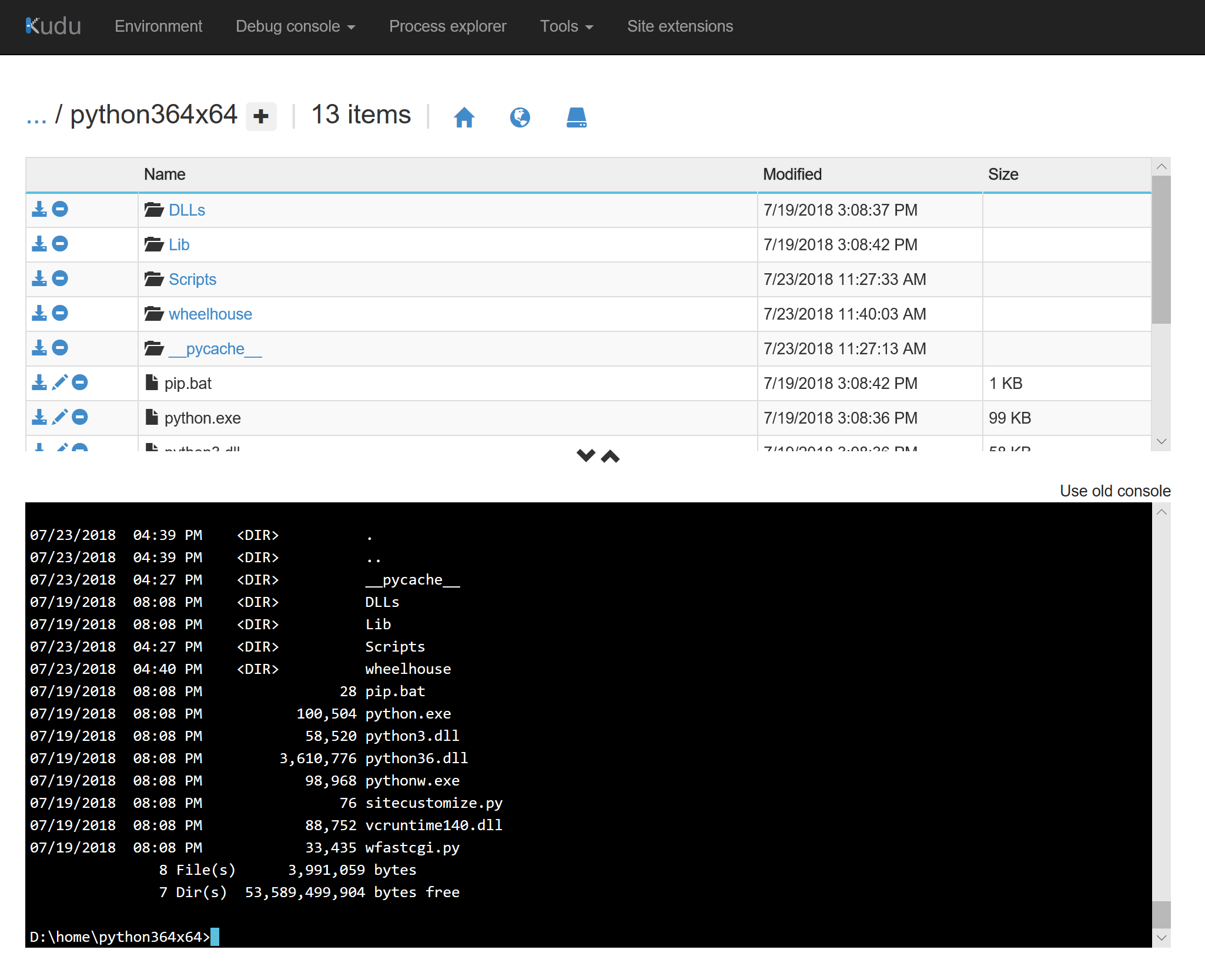
This guide is a reflection on how to use Wheel files to install Modules that cannot natively be installed via pip due to a compiler missing in the Azure App Service:
Add the following item as the first line to the document:
--find-links wheelhouse
Note: If you do not have a requirements.txt file, you can simply create a new text document and add this line to it. The requirements.txt file is what allows the Azure App Service to automatically go out and try and download packages you may need for your application. Official documentation on this file is found here: https://docs.microsoft.com/en-us/azure/app-service/web-sites-python-configure#package-management
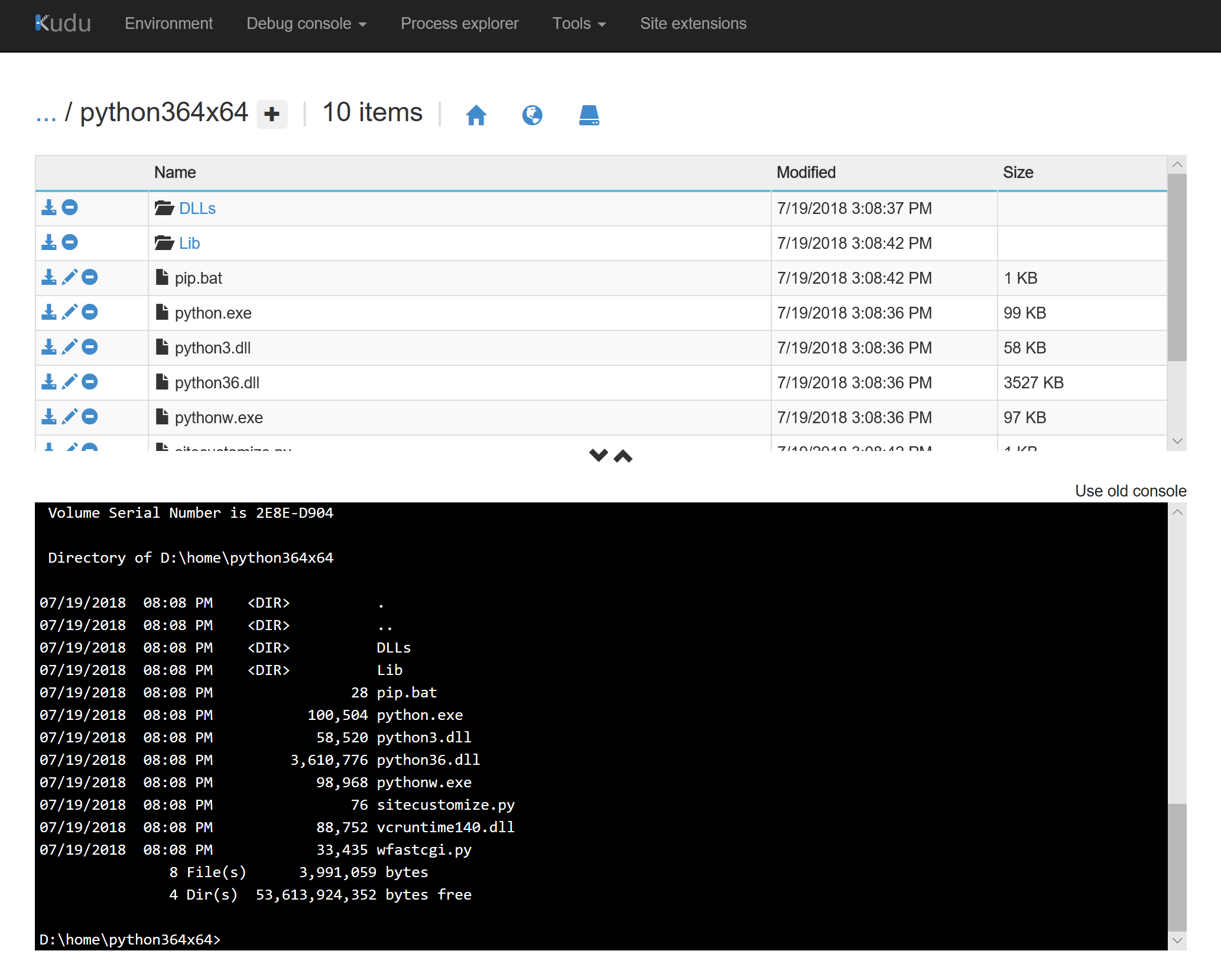
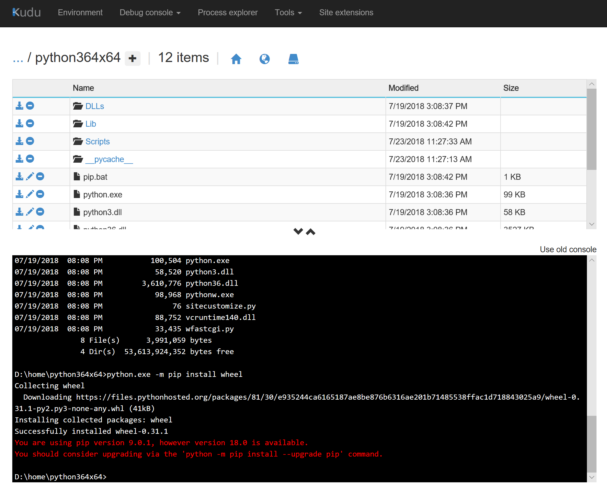
Within the debug console, navigate to your version of Python.
Note: The default Python versions in an Azure App Service are 2.7 and 3.4; however since Wheel will need to install some files, you cannot leverage the default directories of D:\Python27 for v2.7 and D:\Python34 for v3.4
Synopsis: When placing a Virtual Machine on the Azure Platform, by default it inherits time controls from the underlying hypervisor: Hyper-V. The default behavior for these VMs is to synchronize the system clock with the host via the Hyper-V TimeSync service (VMIC) for Hyper-V hosts and guests running prior operating systems to Windows Server 2016.
To disable the Hyper-V Time Provider, we recommend creating a new Group Policy template and targeting your Azure VMs.
Validate that your machine is synchronized to the Hyper-V Time Provider
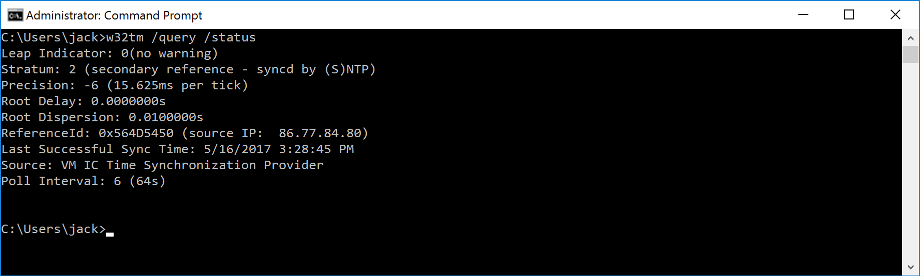
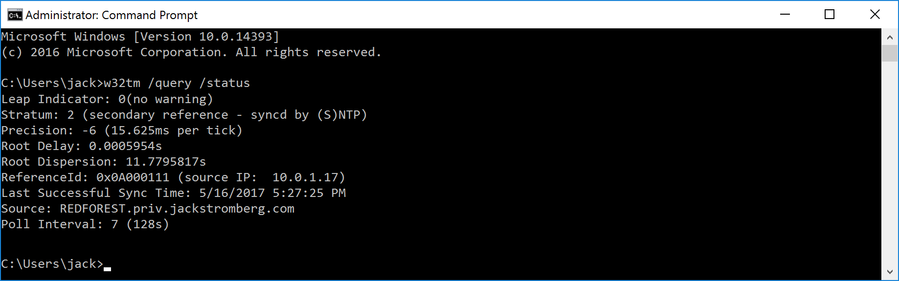
Open command prompt and execute the following command: w32tm /query /status
If you see VM IC Time Synchronization Provider, the Guest OS is synchronized to the VM Host
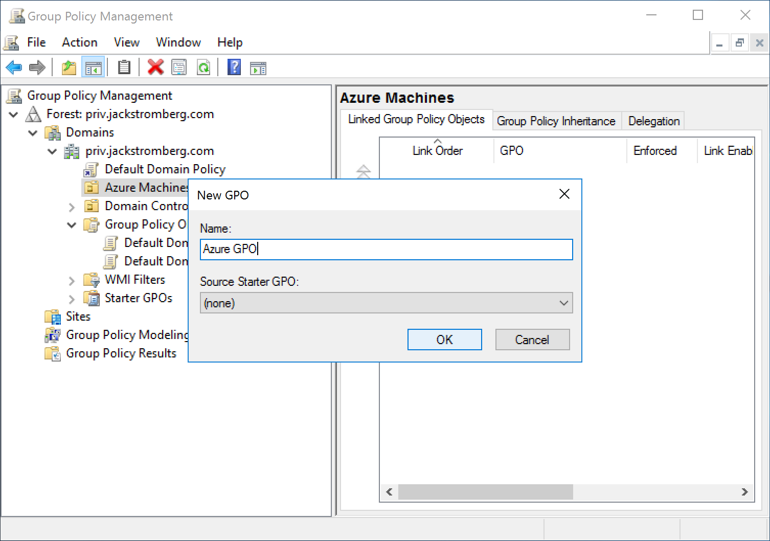
Create a new group policy to disable the Hyper-V Time Provider (VM IC Time Synchronization)
Create a new Group Policy and target it to an OU that contains the machines synchronized to the Hyper-V Time Provider
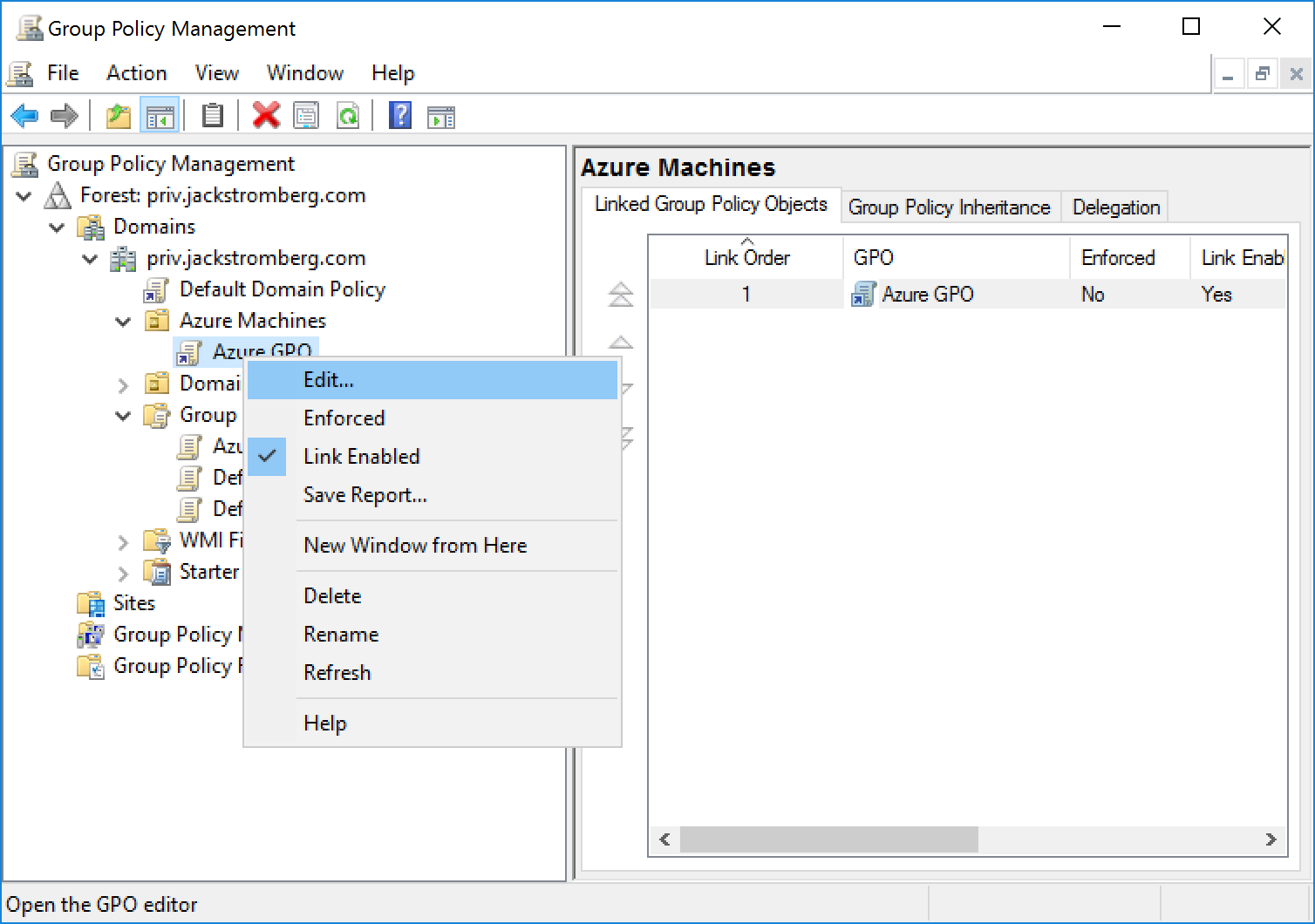
Edit the new Group Policy Object
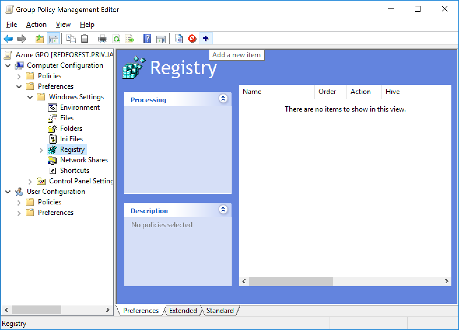
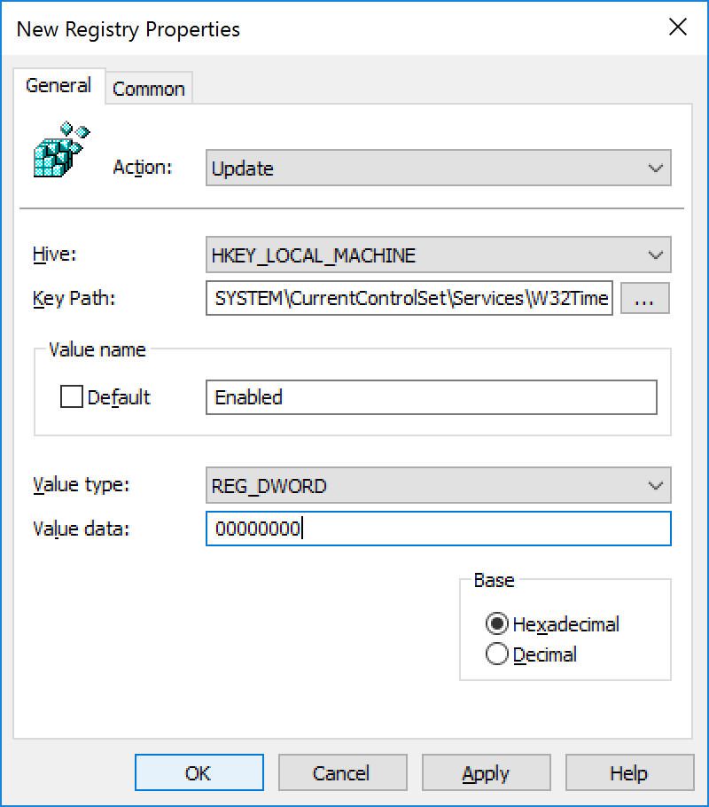
Navigate to Computer configuration -> Preferences -> Windows Settings -> Registry and Add a new item
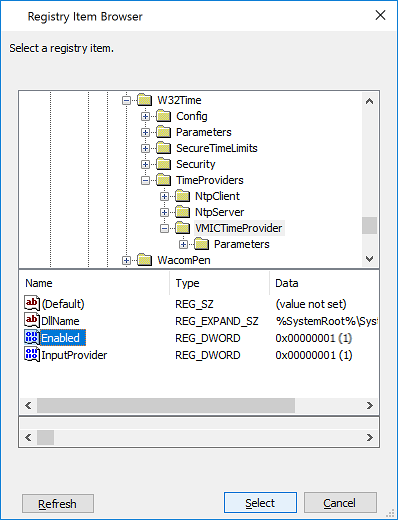
Navigate to the following Key HKLM:SYSTEM\CurrentControlSet\Services\W32Time\TimeProviders\VMICTimeProvider and select the Enabled Value
Change the Value data to 00000000 and click OK
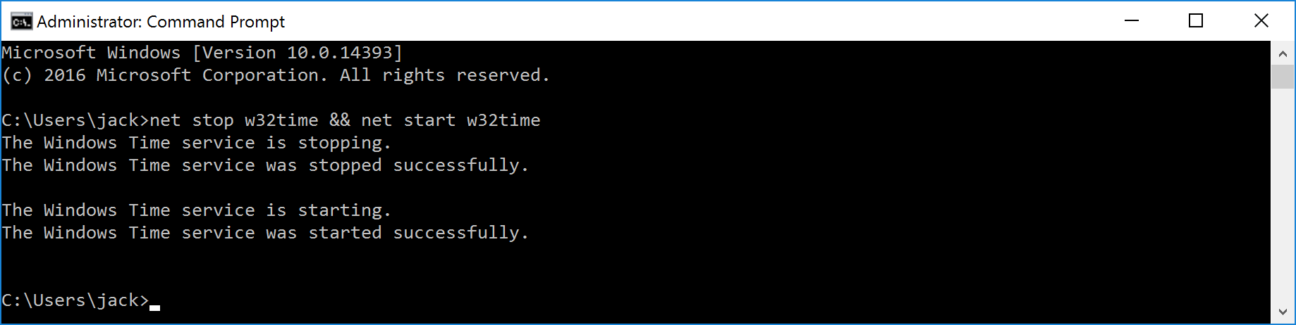
Restart each of the Azure Virtual Machines or login to each machine and execute the following command to restart the Windows Time service: net stop w32time && net start w32time
Validate that the Source is now pointing to your NTP server/domain by running the following command: w32tm /query /status
When creating Azure Automation scripts, you may have to reference time zones by name. Below is a table of acceptable values you may use in your scripts to denote the proper time zone.
Name of Time Zone
Time
Dateline Standard Time
(UTC-12:00) International Date Line West
UTC-11
(UTC-11:00) Coordinated Universal Time-11
Hawaiian Standard Time
(UTC-10:00) Hawaii
Alaskan Standard Time
(UTC-09:00) Alaska
Pacific Standard Time (Mexico)
(UTC-08:00) Baja California
Pacific Standard Time
(UTC-08:00) Pacific Time (US & Canada)
US Mountain Standard Time
(UTC-07:00) Arizona
Mountain Standard Time (Mexico)
(UTC-07:00) Chihuahua, La Paz, Mazatlan
Mountain Standard Time
(UTC-07:00) Mountain Time (US & Canada)
Central America Standard Time
(UTC-06:00) Central America
Central Standard Time
(UTC-06:00) Central Time (US & Canada)
Central Standard Time (Mexico)
(UTC-06:00) Guadalajara, Mexico City, Monterrey
Canada Central Standard Time
(UTC-06:00) Saskatchewan
SA Pacific Standard Time
(UTC-05:00) Bogota, Lima, Quito, Rio Branco
Eastern Standard Time (Mexico)
(UTC-05:00) Chetumal
Eastern Standard Time
(UTC-05:00) Eastern Time (US & Canada)
US Eastern Standard Time
(UTC-05:00) Indiana (East)
Venezuela Standard Time
(UTC-04:30) Caracas
Paraguay Standard Time
(UTC-04:00) Asuncion
Atlantic Standard Time
(UTC-04:00) Atlantic Time (Canada)
Central Brazilian Standard Time
(UTC-04:00) Cuiaba
SA Western Standard Time
(UTC-04:00) Georgetown, La Paz, Manaus, San Juan
Newfoundland Standard Time
(UTC-03:30) Newfoundland
E. South America Standard Time
(UTC-03:00) Brasilia
SA Eastern Standard Time
(UTC-03:00) Cayenne, Fortaleza
Argentina Standard Time
(UTC-03:00) City of Buenos Aires
Greenland Standard Time
(UTC-03:00) Greenland
Montevideo Standard Time
(UTC-03:00) Montevideo
Bahia Standard Time
(UTC-03:00) Salvador
Pacific SA Standard Time
(UTC-03:00) Santiago
UTC-02
(UTC-02:00) Coordinated Universal Time-02
Azores Standard Time
(UTC-01:00) Azores
Cape Verde Standard Time
(UTC-01:00) Cabo Verde Is.
Morocco Standard Time
(UTC) Casablanca
UTC
(UTC) Coordinated Universal Time
GMT Standard Time
(UTC) Dublin, Edinburgh, Lisbon, London
Greenwich Standard Time
(UTC) Monrovia, Reykjavik
W. Europe Standard Time
(UTC+01:00) Amsterdam, Berlin, Bern, Rome, Stockholm, Vienna
Central Europe Standard Time
(UTC+01:00) Belgrade, Bratislava, Budapest, Ljubljana, Prague
Romance Standard Time
(UTC+01:00) Brussels, Copenhagen, Madrid, Paris
Central European Standard Time
(UTC+01:00) Sarajevo, Skopje, Warsaw, Zagreb
W. Central Africa Standard Time
(UTC+01:00) West Central Africa
Namibia Standard Time
(UTC+01:00) Windhoek
Jordan Standard Time
(UTC+02:00) Amman
GTB Standard Time
(UTC+02:00) Athens, Bucharest
Middle East Standard Time
(UTC+02:00) Beirut
Egypt Standard Time
(UTC+02:00) Cairo
Syria Standard Time
(UTC+02:00) Damascus
E. Europe Standard Time
(UTC+02:00) E. Europe
South Africa Standard Time
(UTC+02:00) Harare, Pretoria
FLE Standard Time
(UTC+02:00) Helsinki, Kyiv, Riga, Sofia, Tallinn, Vilnius
Turkey Standard Time
(UTC+02:00) Istanbul
Israel Standard Time
(UTC+02:00) Jerusalem
Kaliningrad Standard Time
(UTC+02:00) Kaliningrad (RTZ 1)
Libya Standard Time
(UTC+02:00) Tripoli
Arabic Standard Time
(UTC+03:00) Baghdad
Arab Standard Time
(UTC+03:00) Kuwait, Riyadh
Belarus Standard Time
(UTC+03:00) Minsk
Russian Standard Time
(UTC+03:00) Moscow, St. Petersburg, Volgograd (RTZ 2)