Here is a recap of some of the reflections I have with deploying Cisco NGFWv (Next Generation Firewall Virtual) on Azure. This is more of a reflection of the steps I took rather than a guide, but you can use the information below as you see fit. At a high level, you will need to deploy the device on Azure and then configure the internal “guts” of the Cisco device to allow it to route traffic properly on your Virtual Network (VNet) in Azure. While Cisco does have decent documentation on deploying a single appliance, the primary purpose of this document is to look at HA/Scale out deployments.
First, just want to provide a quick overview of some of Cisco’s offerings today for Azure:
- Cisco CSR
- In Cisco’s words:
- The Cisco Cloud Services Router (CSR) 1000v is a full-featured Cisco IOS XE router, enabling IT departments to deploy enterprise-class networking services in the Microsoft Azure cloud. Most Cisco IOS XE features are also available on the virtual Cisco CSR 1000v.
- Source: https://www.cisco.com/c/en/us/td/docs/routers/csr1000/software/azu/b_csr1000config-azure/b_csr1000config-azure_chapter_0100.html
- In Cisco’s words:
- Cisco Meraki
- In Cisco’s words:
- Virtual MX is a virtual instance of a Meraki security & SD-WAN appliance, dedicated specifically to providing the simple configuration benefits of site-to-site Auto VPN for customers running or migrating IT services to an Amazon Web Services or Microsoft Azure Virtual Private Cloud (VPC).
- Source: https://meraki.cisco.com/products/appliances/vmx100
- In Cisco’s words:
- Cisco ASAv
- In Cisco’s words:
- The ASAv is a virtualized network security solution that provides policy enforcement and threat inspection across heterogeneous, multisite environments.
- ASA firewall and VPN capabilities help safeguard traffic and multitenant architectures. Available in most hypervisor environments, the Cisco ASAv can be deployed exactly where it is needed to protect users and workloads on-premises or in the cloud.
- Source: https://github.com/cisco/asav
- In Cisco’s words:
- Cisco Firepower NGFW (Threat Defense Virtual)
- In Cisco’s words:
- The Cisco Firepower® NGFW (next-generation firewall) is the industry’s first fully integrated, threat-focused next-gen firewall with unified management. It uniquely provides advanced threat protection before, during, and after attacks.
- The Firepower Threat Defense Virtual (FTDv) is the virtualized component of the Cisco NGFW solution. Organizations employing SDN can rapidly provision and orchestrate flexible network protection with Firepower NGFWv. As well, organizations using NFV can further lower costs utilizing Firepower FTDv.
- Source: https://github.com/cisco/firepower-ngfw
- In Cisco’s words:
Deploy the Appliance in Azure
In deploying the Cisco appliances, you’ll notice you can deploy from the Azure Marketplace: https://azuremarketplace.microsoft.com/en-us/marketplace/apps/cisco.cisco-firepower-threat-defense-appliance?tab=Overview). Personally, I’m not a big fan of deploying the appliance this way as I don’t have as much control over naming conventions, don’t have the ability to deploy more than one appliance for scale, cannot specify my availability set, etc. While Cisco does offer an ARM template, it doesn’t allow flexibility for more than two devices, nor configures anything from a load balancer perspective. In this case, I’ve written a custom ARM template that leverages managed disks, availability sets, consistent naming nomenclature, proper VM sizing, and most importantly, let you define how many virtual instances you’d like to deploy for scaling.
Note: this article doesn’t cover deployment of Cisco’s Firepower Management Center, which is what is used to centrally manage each of the scale-out instances in a “single pane of glass”.
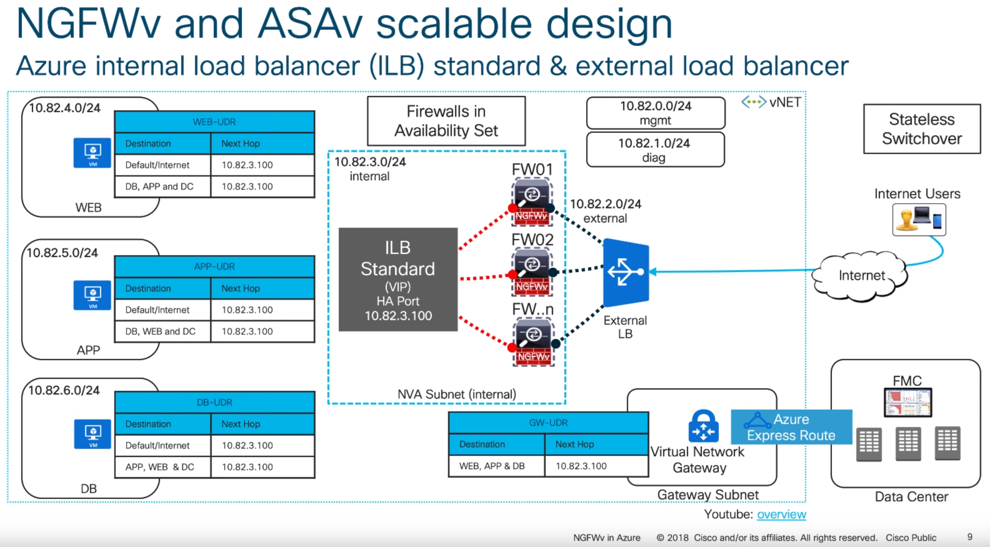
With the above said, this article will cover what Cisco calls their “scalable design” model. Here is an example of what this visually looks like (taken from one of their slide decks listed in the notes section at the bottom of this article):
Below is a link to the ARM template I use.
Deployment of this template can be done by navigating to the Azure Portal (portal.azure.com), select Create a resource, type Template Deployment in the Azure Marketplace, click Create, select Build your own template in the editor, and paste the code into the editor.
Alternatively, you can click this button here:


Here are some notes on what the parameters mean in the template:
VMsize: Per Cisco, the recommend VM sizes should be D3v2, D4v2, or D5v2. Interestingly, they don’t call out the use of Premium storage anywhere, which I would highly recommend using if this was a single instance machine (to get at least some sort of SLA by Azure).
CiscoSku: Here is where you can select to use bring-your-own-license or pay-as-you-go. Plans are should be outlined in the following link, but oddly enough the BYOL image is only available via PowerShell and their plans don’t show it: https://azuremarketplace.microsoft.com/en-us/marketplace/apps/cisco.cisco-firepower-threat-defense-appliance?tab=PlansAndPrice
CiscoVersion: The version of the Cisco appliance to deploy.
CiscoCount: This defines how many virtual instances you want deployed and placed behind load balancers.
VNetName: The name of your virtual network you have created.
VNetRG: The name of the resource group your virtual network is in. This may be the same as the Resource Group you are placing the Cisco devices in, but this is a needed configurable option to prevent errors referencing a VNet in a different resource group.
envPrefix: All of the resources that get created (load balancer, virtual machines, public IPs, NICs, etc.) will use this naming nomenclature.
manPrivateIPPrefix, diagPrivateIPPrefix, trustPrivateIPPrefix, untrustPrivateIPPrefix: Corresponding subnet address range. These should be the first 3 octets of the range followed by a period. For example, 10.5.6. would be a valid value.
manPrivateIPFirst, diagPrivateIPFirst, trustPrivateIPFirst, untrustPrivateIPFirst: The first usable IP address on the subnet specified. For example, if my subnet is 10.4.255.0/24, I would need to specify 4 as my first usable address.
Username: this is the name of the privileged account that should be used to ssh and login to the PanOS web portal.
NewStorageAccountName: this is the name of the storage account that will store boot diagnostics for the Cisco appliances. This will give you the ability to see what the serial console shows. This value should be alphanumeric and 3-24 characters.
Password: Password to the privileged account used to ssh and login to the device.
Configure the Appliance
Complete these steps for both devices.
- SSH to the device via it’s public or private IP address of the management interface
- Please note, SSH may not come up for another 10+ minutes after deployment has finished, even though the VMs show running. There are several tasks within the Cisco appliance that run post-provisioning which take awhile to complete before the ability to SSH works.
- Login using the following credentials
- Note: Even though we specified credentials within our template, cisco has a default set of admin credentials “baked” into the image and they should be specified during first login (which prompts you to immediately change). Please login using the default admin credentials.
- Username: admin
- Password: Admin123
- The password is case sensitive, you should use a capital A on Admin123.
- Change your password once prompted
- Enter y to configure IPv4
- Enter n to not configure IPv6
- As of 6/1/2019, Azure only has preview support for IPv6, so this article won’t cover any IPv6 specific items
- Enter dhcp to configure IPv4 with DHCP
- All addresses in Azure should be DHCP, static addresses are set within Azure, which essentially give the appliance a DHCP reservation
- Important Note: Once you configure this option, you’ll get an awkward “If your networking information has changed, you will need to reconnect” message and things will appears to be stuck. Be patient, it appears a script runs in the background, you’ll see it eventually prompt for the next question.
- Leave your SSH connection open for the next step
Configure NGFWv to use FirePower Management Center
Once you have gone through the initial configuration on both devices, you will need to register the sensor to a Firepower Management Center instance. To do this, you will need to run the configure manager command on both appliances. Please note I’ve listed the command below with the parameters it will accept, you will need to use the applicable values for your environment.
configure manager add {hostname | IPv4_address | IPv6_address | DONTRESOLVE} reg_key [nat_id]
Per Cisco’s documentation:
- The registration key is a user-defined one-time use key that must not exceed 37 characters. Valid characters include alphanumeric characters (A–Z, a–z, 0–9) and the hyphen (-). You will need to remember this registration key when you add the device to the Firepower Management Center.
- If the Firepower Management Center is not directly addressable, use DONTRESOLVE.
- The NAT ID is an optional user-defined alphanumeric string that follows the same conventions as the registration key described above. It is required if the hostname is set to DONTRESOLVE. You will need to
remember this NAT ID when you add the device to the Firepower Management Center
Add the appliances into FirePower Management Center
Repeat the following steps for each of the appliances you deployed
- Login to FirePower Management Center
- Select the Devices tab, click Device Management, and then click the Add button
- Enter the following
- Host: ManagementIP
- Device Name: FriendlyDeviceNameOrHostName
- Registration Key: KeyYouUsedWhenRunningConfigureManagerCommandAbove
- Access Control Panel
- Specify a Name, select Network Discovery
- Smart Licensing
- Check the following you are licensed for
- Malware
- Threat
- URL Filtering
- Check the following you are licensed for
- If you used NAT, configure NAT and specify the NAT ID
- Click Register
Initialize the interfaces on your appliances
Repeat the following steps for each of the appliances you deployed
- Select the Devices tab, click Device Management, and select the edit button (Pencil Icon) for your appliance
- Click the edit button (Pencil Icon) for GigabitEthernet 0/0
- Name: Untrust
- Check the Enabled checkbox
- Security Zone: Create a new zone called Untrusted
- Click the IPv4 tab
- IP Type: Use Static
- IP Address: IPAddressOfYourAppliance/SubnetSize
- Click OK
- Click the edit button (Pencil Icon) for GigabitEthernet 0/1
- Name: Trust
- Check the Enabled checkbox
- Security Zone: Create a new zone called Trusted
- Click the IPv4 tab
- P Type: Use Static
- IP Address: IPAddressOfYourAppliance/SubnetSize
- Click OK
- Click the Save button
Once you have completed the steps above, click Deploy, select each of your appliances, and click Deploy to push the configuration to the device
Configure static routes on your device
In this section, we will create several routes to handle the flow of traffic to and to/from your trusted subnets, traffic destined towards the internal, traffic destined towards the management interface (we’ll need this to help handle the health probes from the azure load balancer later on), and a specific route to define the Azure Health Probes themselves.
Repeat the following steps for each of the appliances you deployed.
- Select the Devices tab, click Device Management, and select the edit button (Pencil Icon) for your appliance
- Select the Routing tab and click Static Route
- Click the Add Route button
- Type: IPv4
- Interface: Trust
- Create new network objects
- Add network objects that represent each of the subnets you have in Azure that the device will need to return traffic to
- For example, you’d repeat these steps for each private subnet
- Name: DBServers
- Network: 10.3.5.0/24
- Click Save
- For example, you’d repeat these steps for each private subnet
- Add network object for the appliance’s management interface
- Name: YourAppliance-mgmt
- Network: IPAddressOfManagementInterface
- Use the private IP of your management interface
- Click Save
- Add network object for Azure Health Probes
- Name: Azure-LB-Probe
- Network: 168.63.129.16
- Click Save
- Add network objects that represent each of the subnets you have in Azure that the device will need to return traffic to
- Add the defined network objects above to Selected Network box
- Gateway: Use the IP address of the default gateway of your subnet the Trust interface is deployed on
- Note: To find this, navigate to the Azure Portal (portal.azure.com) and select All Services -> Virtual Networks -> Your Virtual Network -> Subnets and use the first IP address of your subnet the trusted interface is on. For example, if the address range of my subnet is 10.5.15.0/24, I would use 10.5.15.1 as my IP address. If my subnet was 10.5.15.128/25, I would use 129 10.5.15.129 as my IP address
- Metric: 3
- Click OK
- Click the Add Route button
- Type: IPv4
- Interface: Untrust
- Add the any-ipv4 object to Selected Network box
- This will allow us to force all internet bound traffic through our Untrust interface
- Add the Azure-LB-Probe object to the Selected Network box
- This will allow health probes from the external azure load balancer probes to flow properly
- Add the YourAppliance-mgmt object to the Selected Network box
- Gateway: Use the IP address of the default gateway of your subnet the Untrust interface is deployed on
- Note: To find this, navigate to the Azure Portal (portal.azure.com) and select All Services -> Virtual Networks -> Your Virtual Network -> Subnets and use the first IP address of your subnet the untrusted interface is on. For example, is the address range of my subnet is 10.5.15.0/24, I would use 10.5.15.1 as my IP address. If my subnet was 10.5.15.128/25, I would use 129 10.5.15.129 as my IP address
- Metric: 2
- Click OK
- Click the Save button
Once you have completed the steps above, click Deploy, select each of your appliances, and click Deploy to push the configuration to the device
Configure NAT Policies
First create a NAT rule that will SNAT any traffic from our trusted zone to the Untrust interface. This is needed so Azure understands to return traffic through the external interface of your device for inspection.
- Select the Devices tab, click NAT, and select the Threat Defense NAT Policy link (or New Policy button)
- Select your first appliance, click the Add to Policy button, and click Save
- Click the Add Rule button
- NAT Rule: Auto NAT Rule
- Type: Dynamic
- Interface Objects Tab
- Select the Trusted Interface Object and click the Add to Source button
- Select the Untrusted Interface object and click the Add to Destination button
- Translation Tab
- Click the green button to add a new network object under Original Packet
- Name: any-ipv4
- Network: 0.0.0.0/0
- Click Save
- Original Source: any-ipv4
- Translated Source: Destination Interface IP
- Click the green button to add a new network object under Original Packet
- Click OK
Next, we need to create a new NAT statement to handle traffic for our load balancer probes. We will need to configure two statements since we will receive health probes from the same IP address (168.63.129.16) to both NICs. On the same appliance, continue the following steps.
- Click the Add Rule button
- NAT Rule: Manual NAT Rule
- Type: Static
- Interface Objects Tab
- Select the Trusted Interface Object and click the Add to Source button
- Select the Untrusted Interface object and click the Add to Destination button
- Translation Tab
- Original Source: Azure-LB-Probe
- Original Destination: Source Interface IP
- Original Destination Port: SSH
- Translated Source: Destination Interface IP
- Translated Destination: YourAppliance-mgmt
- Translated Destination Port: SSH
- Click OK
- Click the Add Rule button
- NAT Rule: Manual NAT Rule
- Type: Static
- Interface Objects Tab
- Select the Untrusted Interface Object and click the Add to Source button
- Select the Trusted Interface object and click the Add to Destination button
- Translation Tab
- Original Source: Azure-LB-Probe
- Original Destination: Source Interface IP
- Original Destination Port: SSH
- Translated Source: Destination Interface IP
- Translated Destination: YourAppliance-mgmt
- Translated Destination Port: SSH
- Click OK
Optional Step: If you are using the appliances to front applications to the internet, you will also need to configure a NAT rule for ingress traffic. This is an optional step, but will show you how to configure traffic to let’s say a web server (which the ALB is configured to listen for per the template). If you do complete this step, make sure you add an access policy (Policies -> Access Control -> Select your policy -> click Add Rule).
- Click the Add Rule button
- NAT Rule: Manual NAT Rule
- Type: Static
- Interface Objects Tab
- Select the Untrusted Interface Object and click the Add to Source button
- Select the Trusted Interface object and click the Add to Destination button
- Translation Tab
- Original Source: any-ipv4
- Original Destination: Source Interface IP
- Original Destination Port: HTTP
- Translated Source: Destination Interface IP
- Translated Destination: webserver
- Click the green add button to create a new network object to define the private IP address of your web server.
- Translated Destination Port: HTTP
- Click OK
Click Save once you have finished adding the rules.
At this point, you will need to repeat the same steps above. The reason why we cannot apply the policy to both devices is when you configure the rule for the Azure Health Probes, you’ll need to specify the correct Translated Destination (I.e. Appliance1 should use the network object that resolves to appliance 1; Appliance2 should use the network object that resolves to appliance 2)
Once you have completed the steps above, click Deploy, select each of your appliances, and click Deploy to push the configuration to the device
Finalize the environment
Now that the environment is configured, there are two steps you will want to check back on.
- Add Route Tables to each subnet to force traffic to the Cisco appliances
- You will need to leverage route tables with custom routes to force traffic to the Cisco appliance. I’d highly recommend giving this a read to familiarize yourself with how Route Tables work in Azure: https://docs.microsoft.com/en-us/azure/virtual-network/virtual-networks-udr-overview
- Ensure there is a Network Security Group (NSG) on the Untrust subnet
- As per Azure Load Balancer’s documentation, you will need an NSG associated to the NICs or subnet to allow traffic in from the internet. https://docs.microsoft.com/en-us/azure/load-balancer/load-balancer-standard-overview#securebydefault
- Remove the public IP from your management interface
- Considering at this point you’ve configured the device and have private connectivity via VPN or ExpressRoute, I’d remove the public IP from your management interface to prevent the public internet from accessing this interface
- Adjust NSG rules
- Similar to above, I’d scope down who/what network segments can pass traffic to the device. Go back and modify the NSG on the management interfaces to only allow traffic from specific source addresses.
References
- NGFW/ASAv Architecture as defined by Cisco https://www.youtube.com/watch?v=n3tyF9FbUr0 https://www.youtube.com/watch?v=Zjc9hmc2m68
https://www.youtube.com/watch?v=s9WlDXAI3fM - NGFW FTDV docs (pre-HA features): https://www.cisco.com/c/en/us/td/docs/security/firepower/quick_start/azure/ftdv-azure-qsg.pdf
- NGFW/ASAv HA Architecture from Cisco Live BRKSEC-2064: https://www.ciscolive.com/c/dam/r/ciscolive/apjc/docs/2018/pdf/BRKSEC-2064.pdf