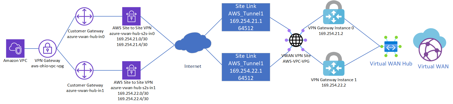
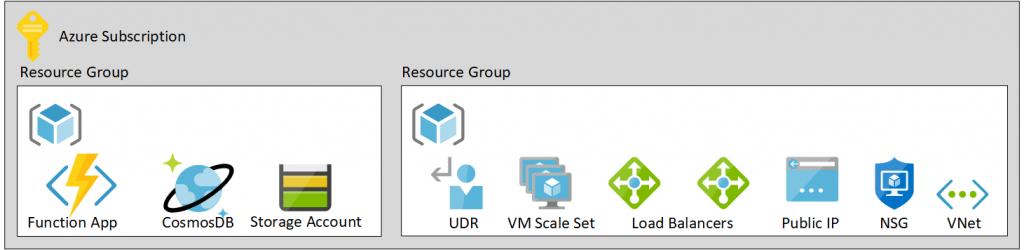
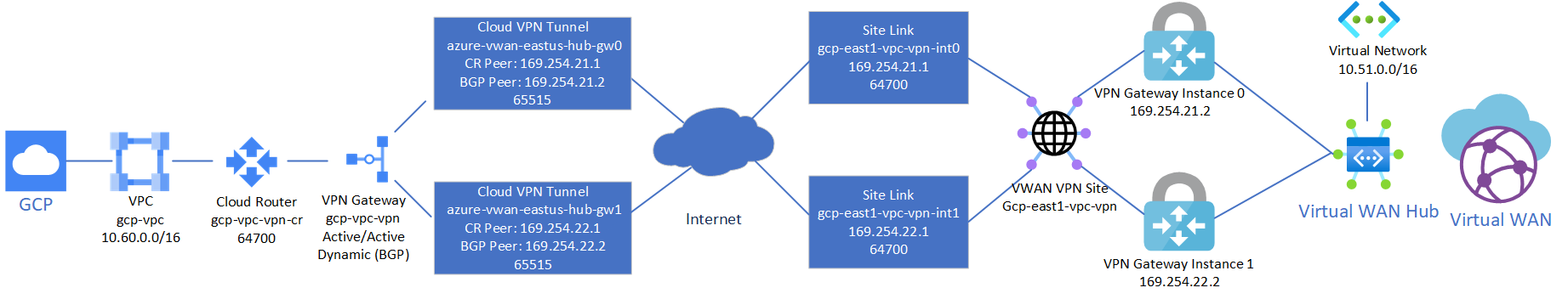
This is a quick reflection of the steps I took to establish two IPSec tunnels between GCP’s VPC and Azure’s Virtual WAN VPN Gateway, propagating routes dynamically via BPG and ensuring High Availability. The design is fairly straightforward since both GCP and Azure offer the ability to established multiple connections to remote peers. When everything is said and done, you’ll end up with a diagram that conceptually looks something like this:
Note: It is recommended to complete the steps in this document in the outlined order to complete the least amount of steps. In this case, provide Azure Virtual WAN first, then configure GCP, then create the Azure Virtual WAN Site Links / Connections to GCP.
Note 2: If you have followed my previous guide on establishing an AWS VPN tunnel to Azure Virtual WAN , this guide will co-exist both connections and can skip the Create Azure Virtual WAN and Virtual WAN Hub sections.
Create Azure Virtual WAN and Virtual WAN Hub
On the Azure side, first we need to create a Virtual WAN resource and a Virtual WAN Hub, which will contain our VPN Gateway. If you have already created these, you can skip to the next session.
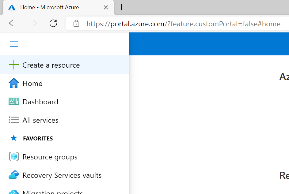
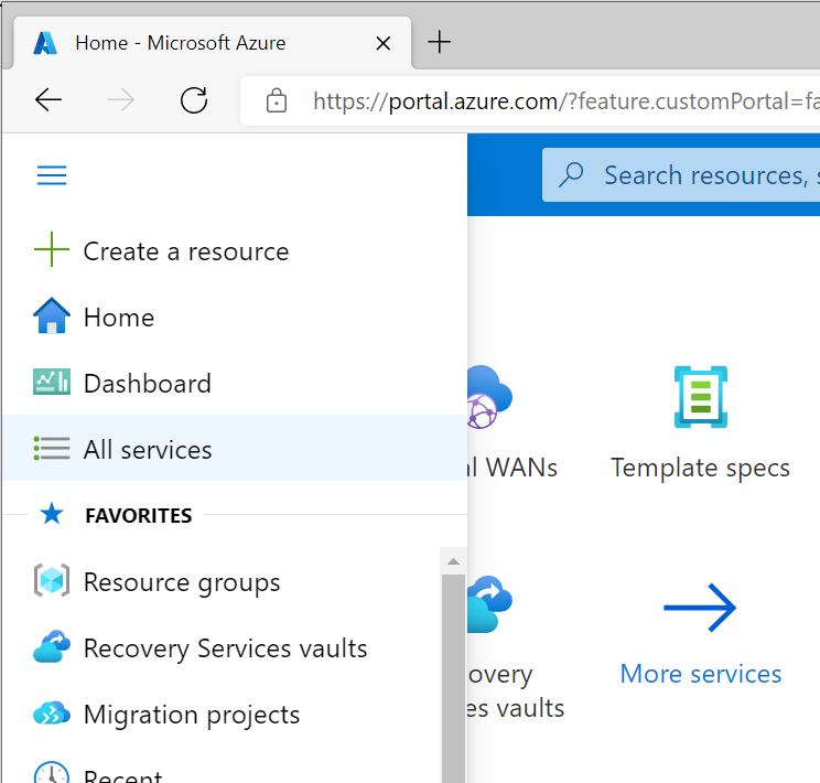
First, click the “Hamburger” icon and select Create a resource
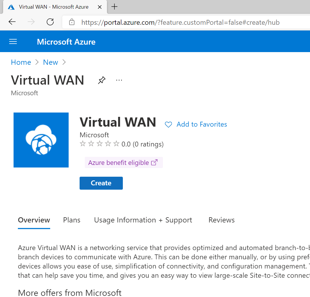
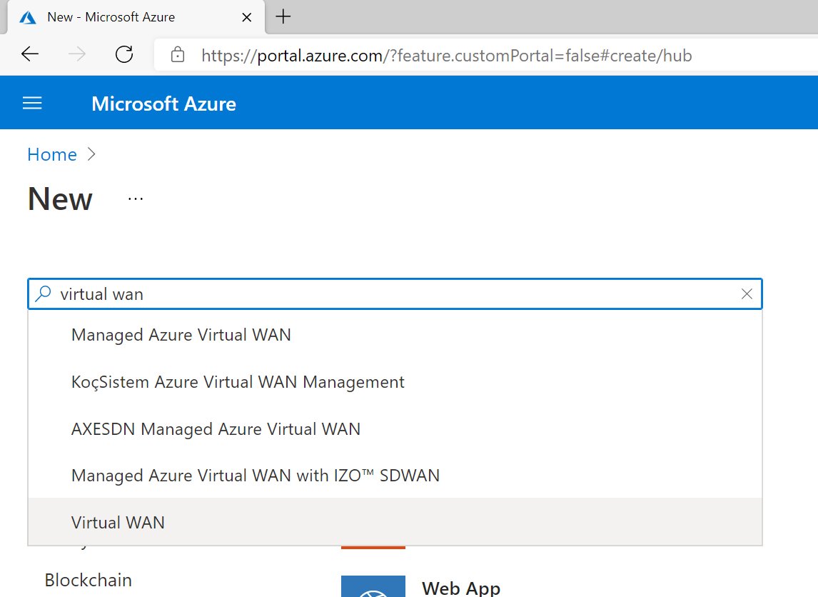
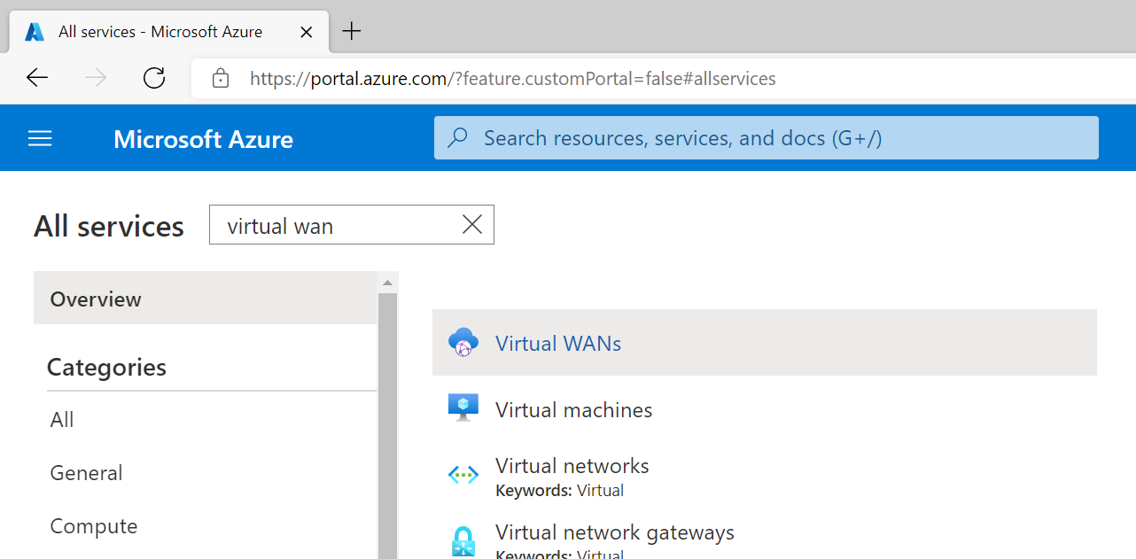
Search for Virtual WAN and select it from the list in the marketplace.
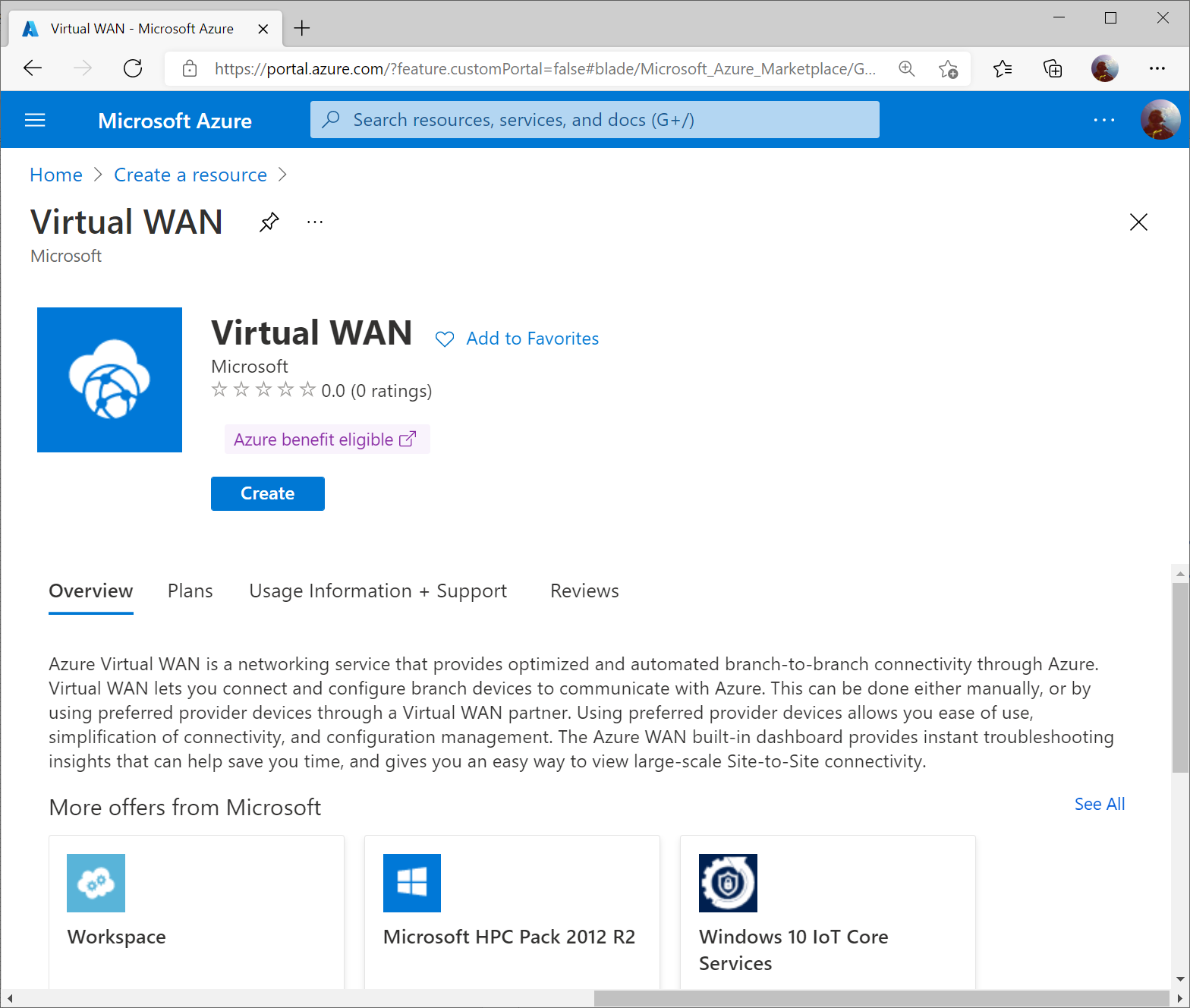
Select Create
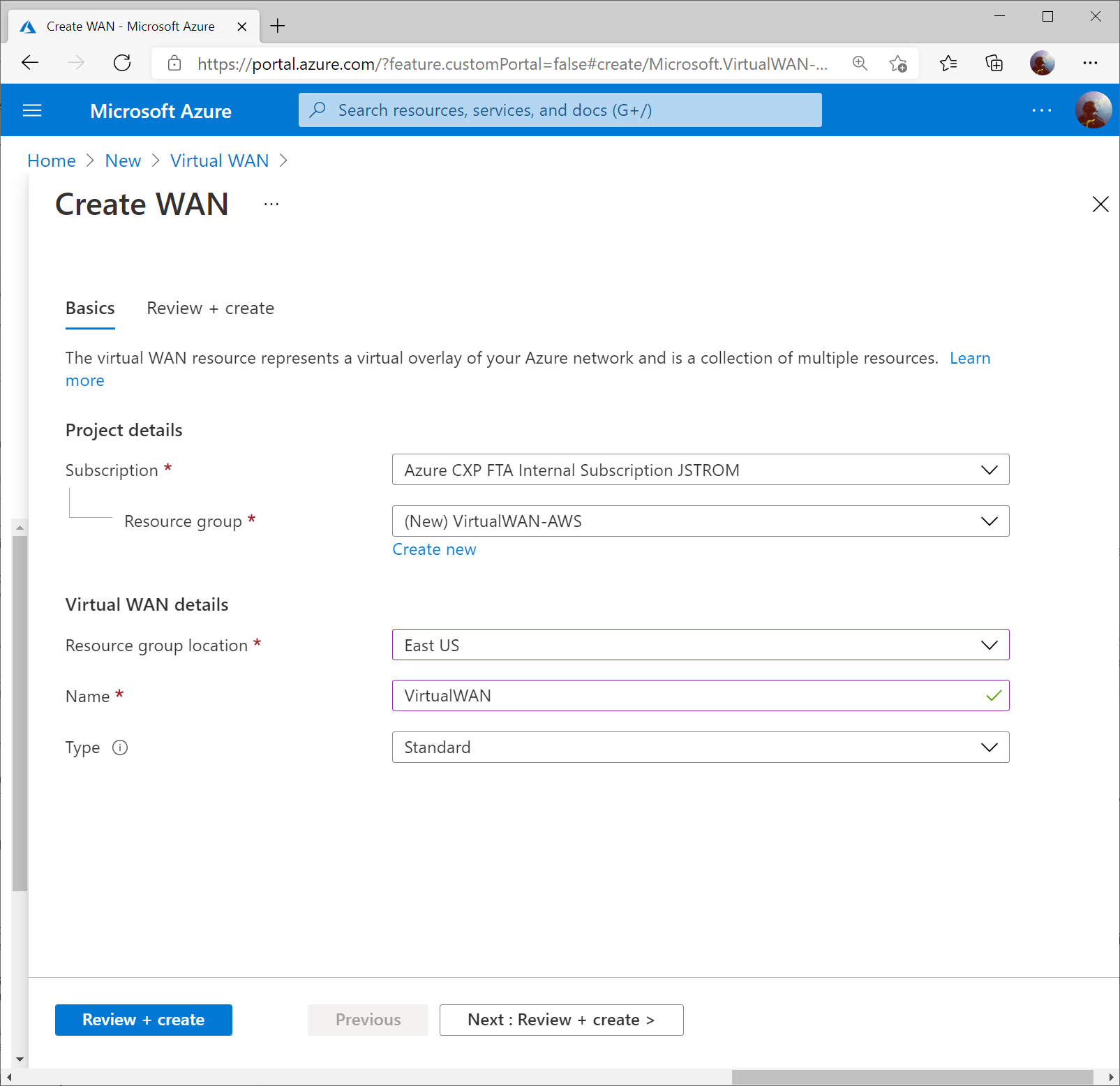
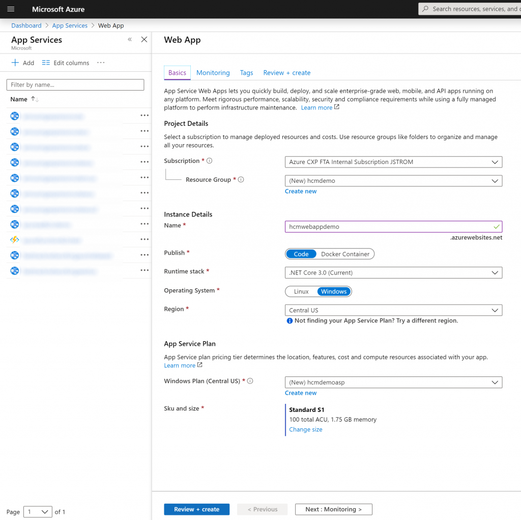
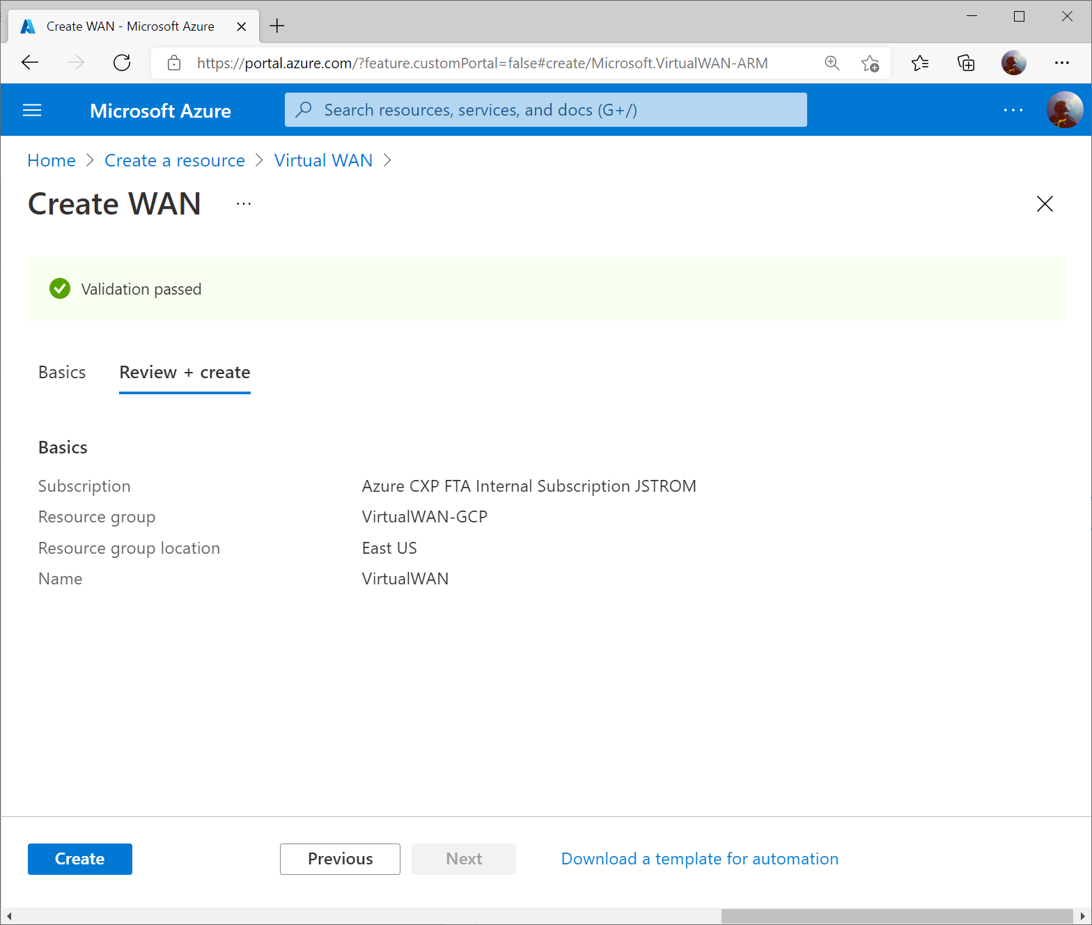
Specify the resource group and region you wish to deploy the Virtual WAN resource to. Specify a name for your Virtual WAN resource and click Review + Create

Click Create to start provisioning the Virtual WAN resource.
Once the resource is created, click Go to resource to navigate to your Virtual WAN resource.

On the Virtual WAN resource, select New Hub from the top menu.
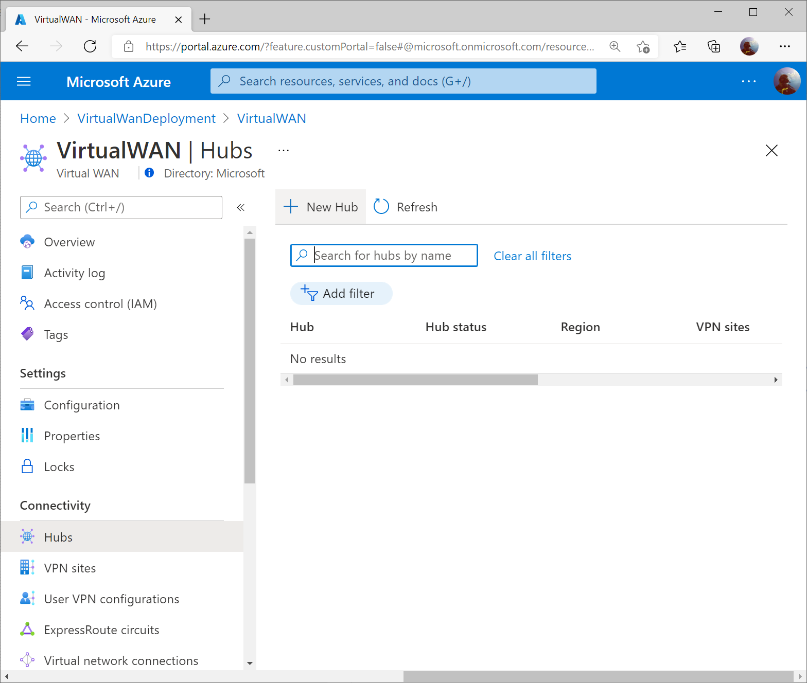
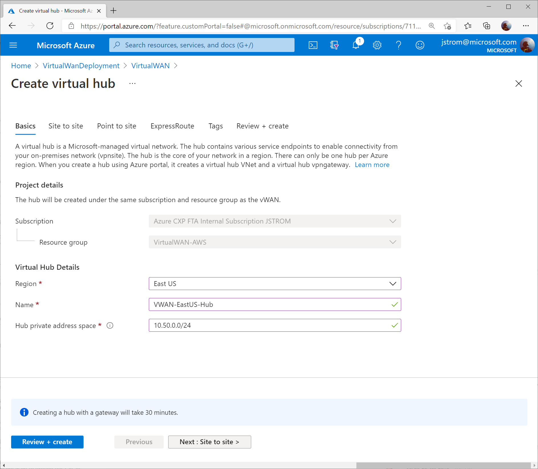
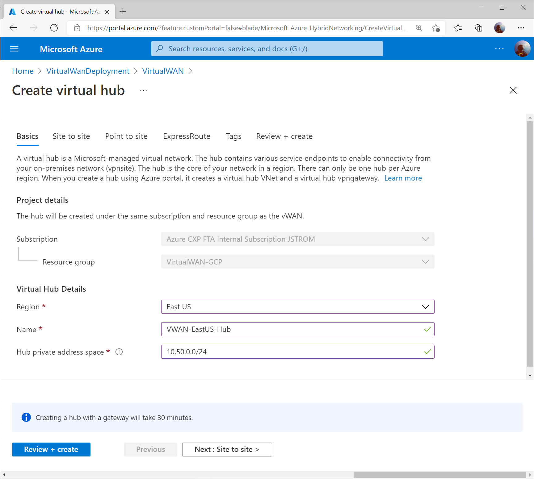
Specify the name of the Hub and an address space that can be used for all the networking components Virtual WAN will deploy into the Virtual Hub. Click Next : Site to Site >
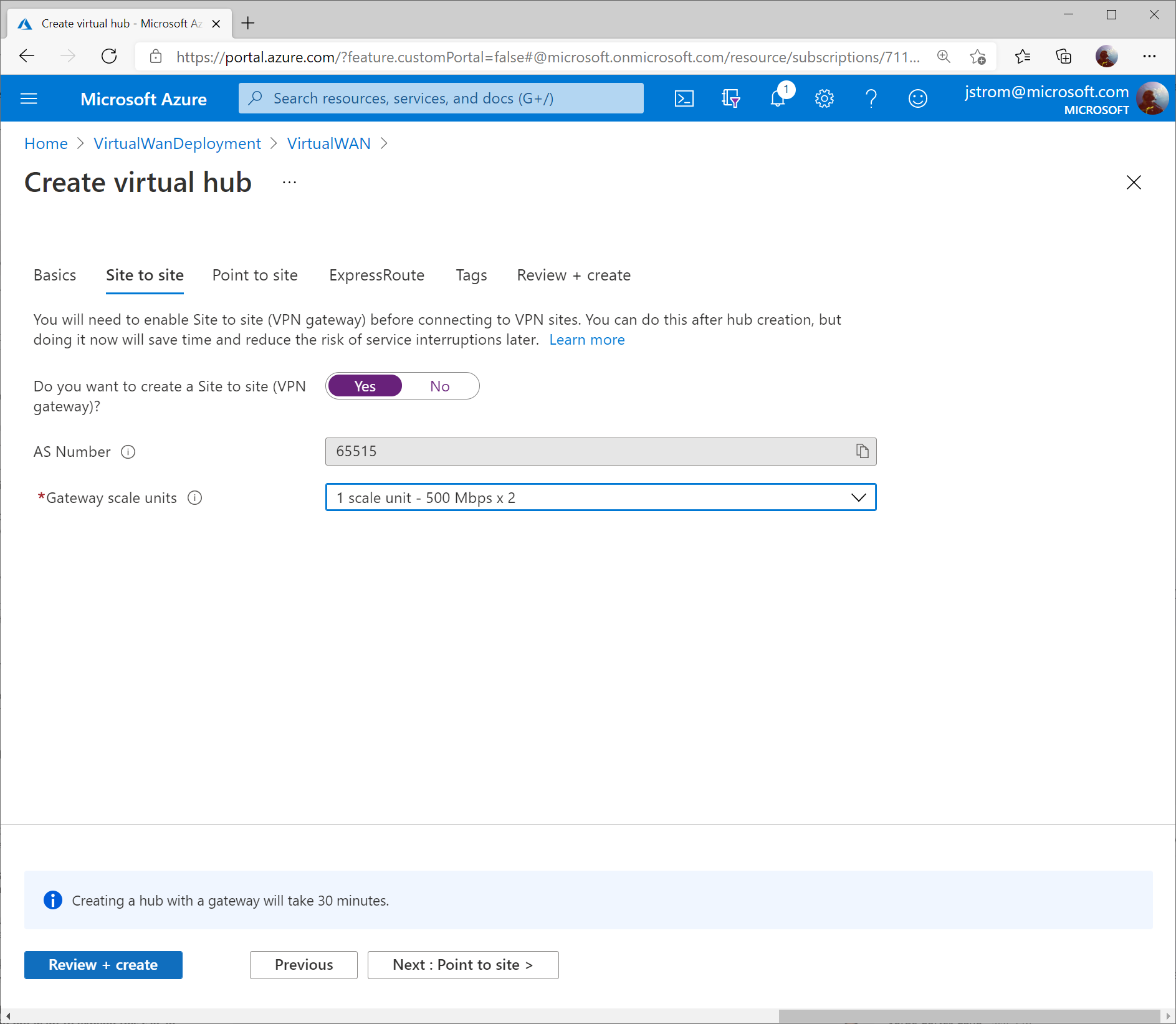
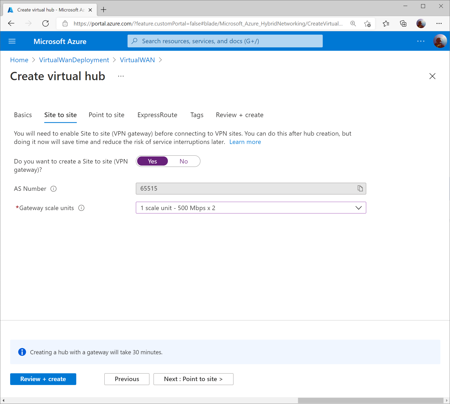
On the Site to Site tab, toggle Yes that you want to provision a VPN Gateway, and specify the scale units you need. Click the Review + create button when done.
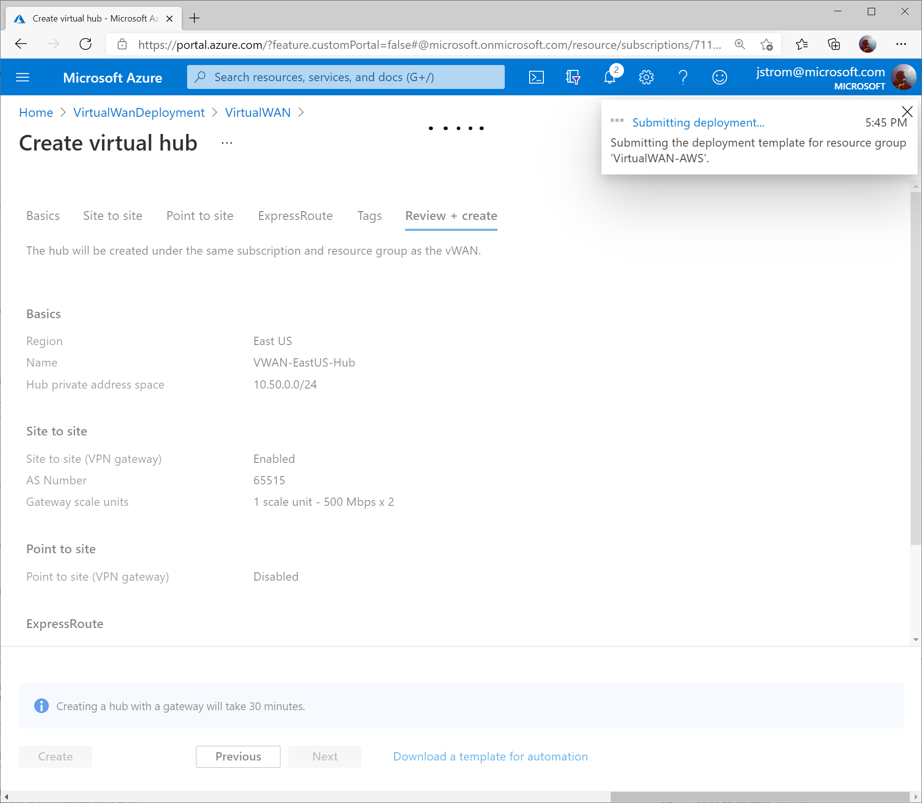
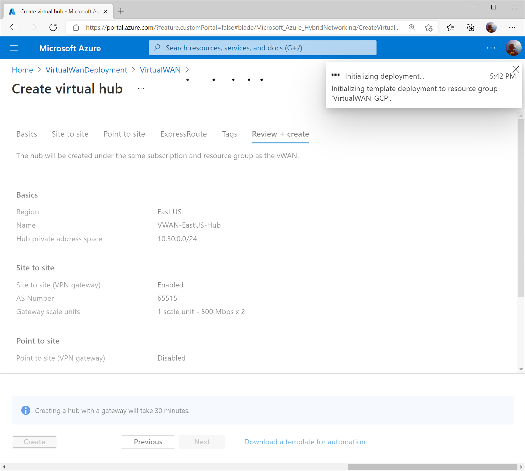
Click the Create button to start provisioning the Hub and VPN Gateway. Please note this can take up to 30 minutes to complete.
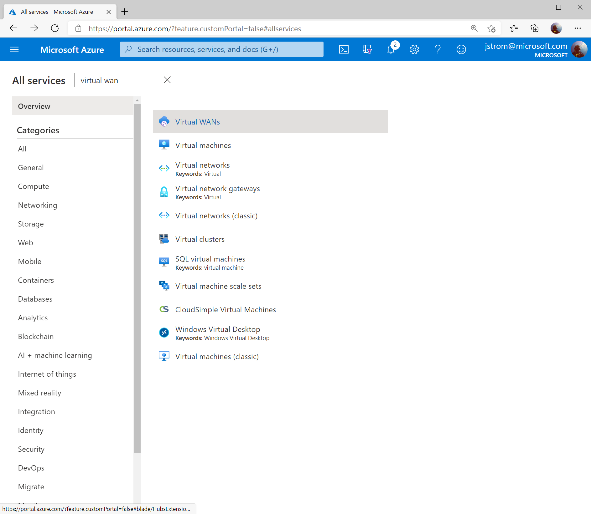
Once the Virtual WAN Hub has been created, click the Menu icon and select All services (note: if you click the Go to resource button after the Virtual WAN Hub resource is created, it’ll take you the properties of the Hub, which isn’t where we want to be).
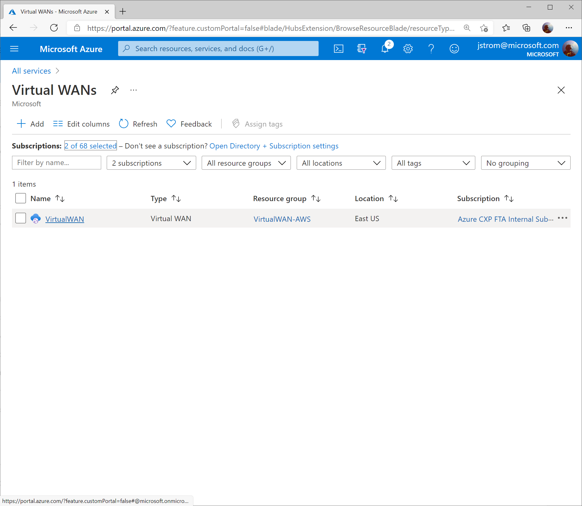
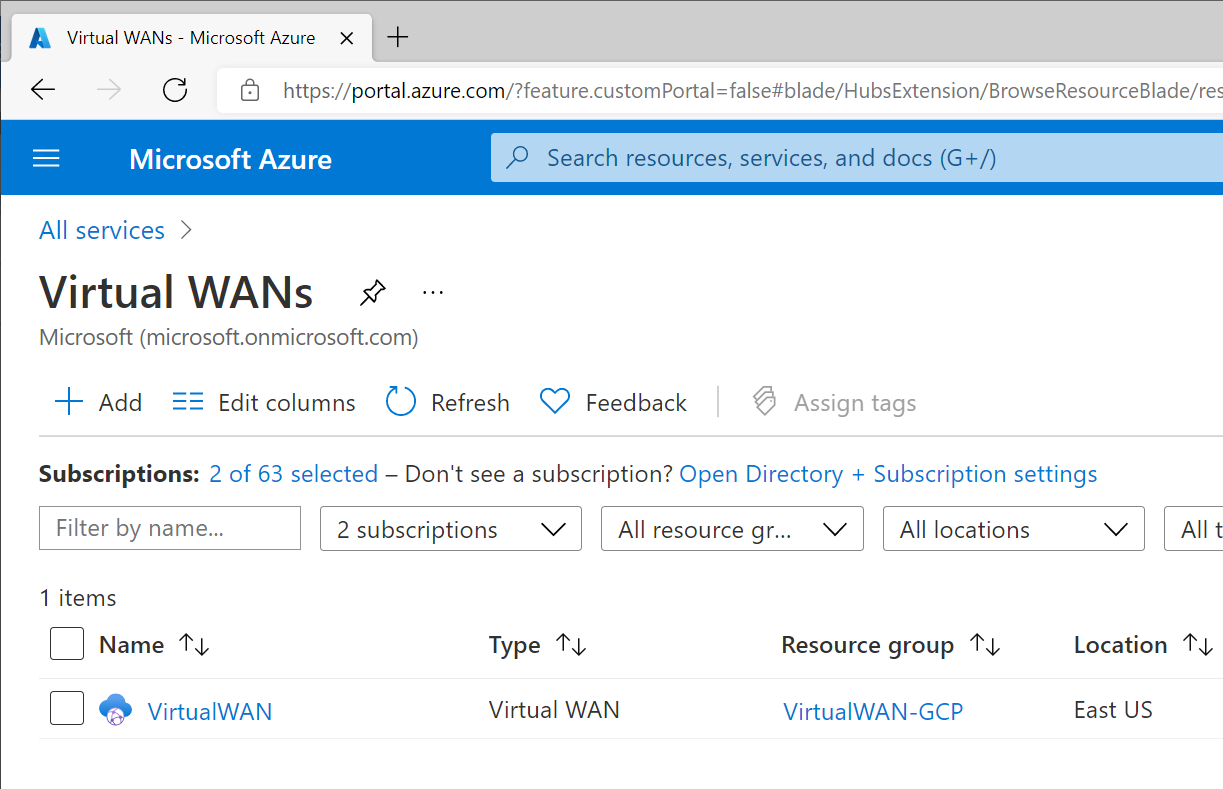
Search for Virtual WAN and select Virtual WANs.
Select your Virtual WAN resource.
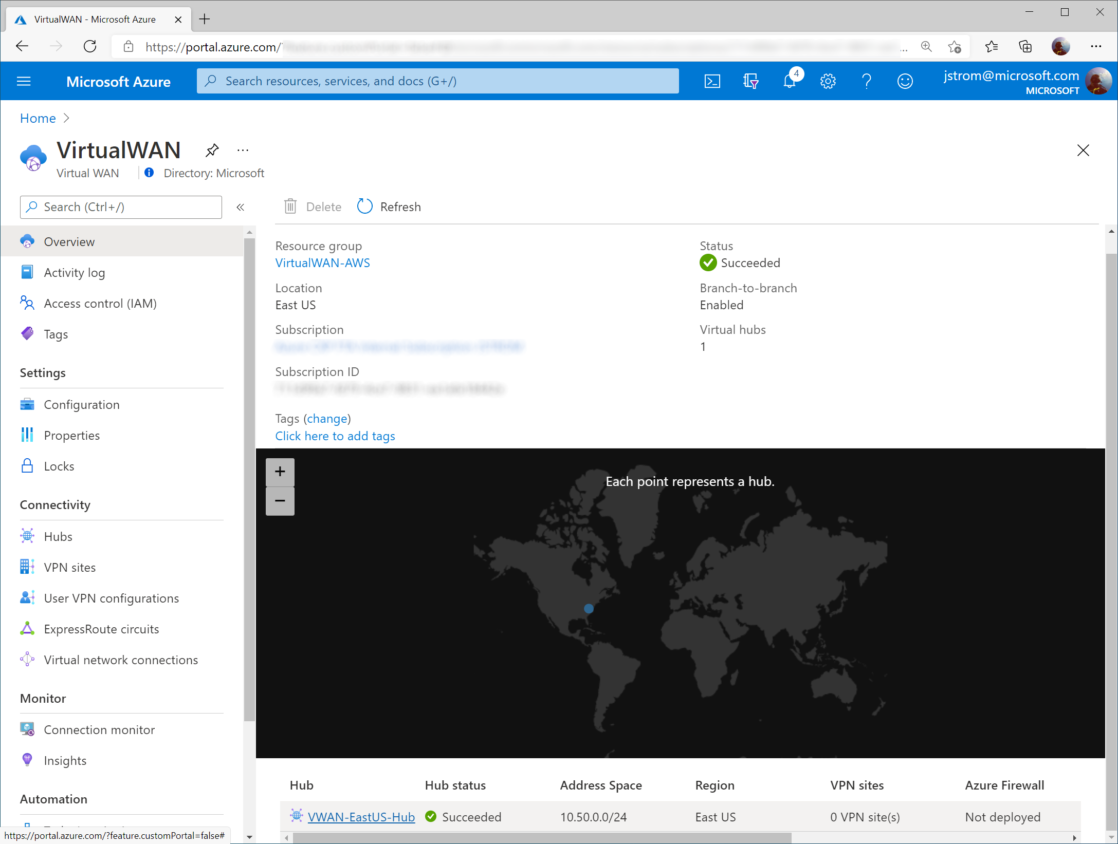
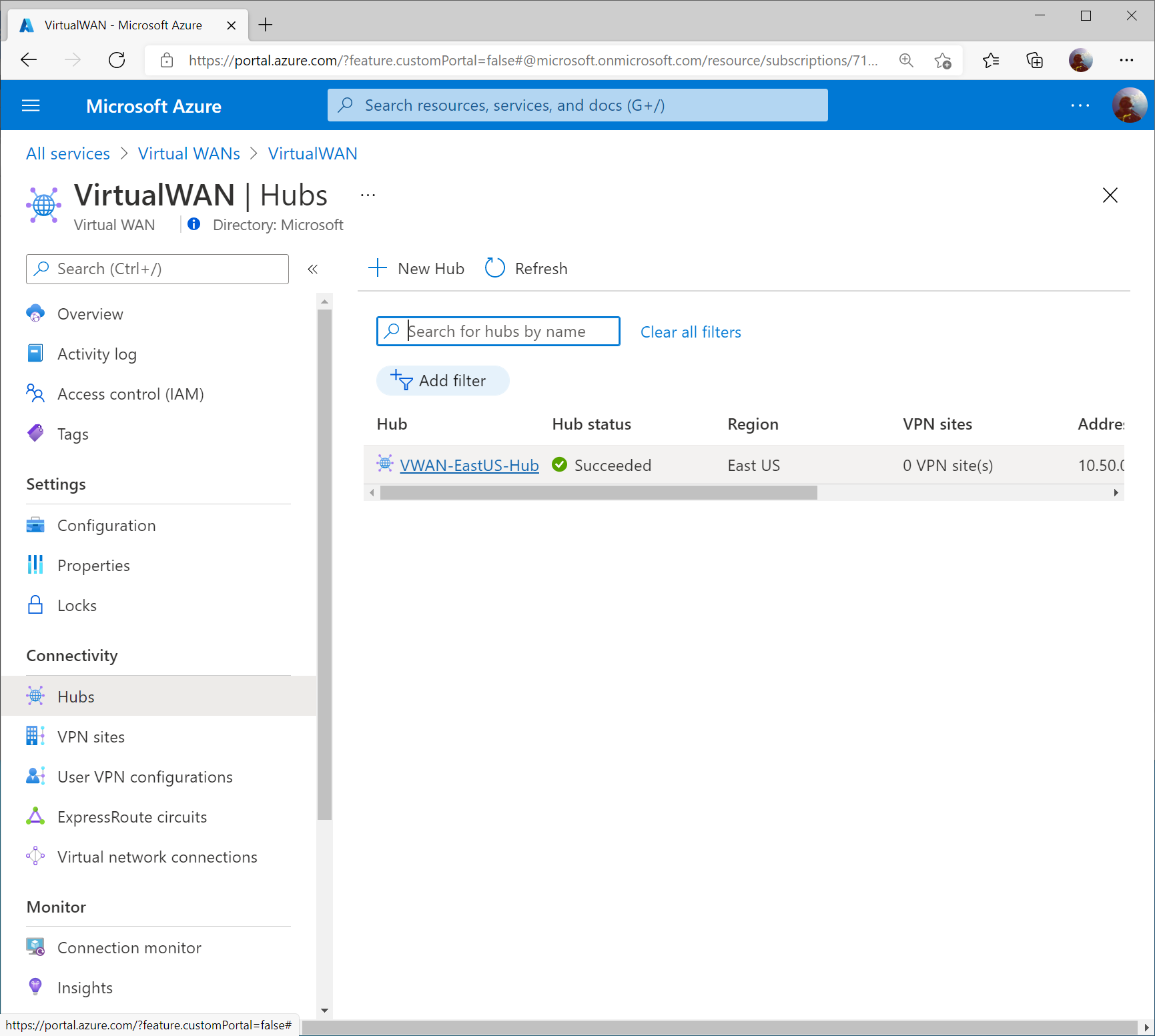
Click on Hubs under Connectivity and select your Virtual WAN Hub.
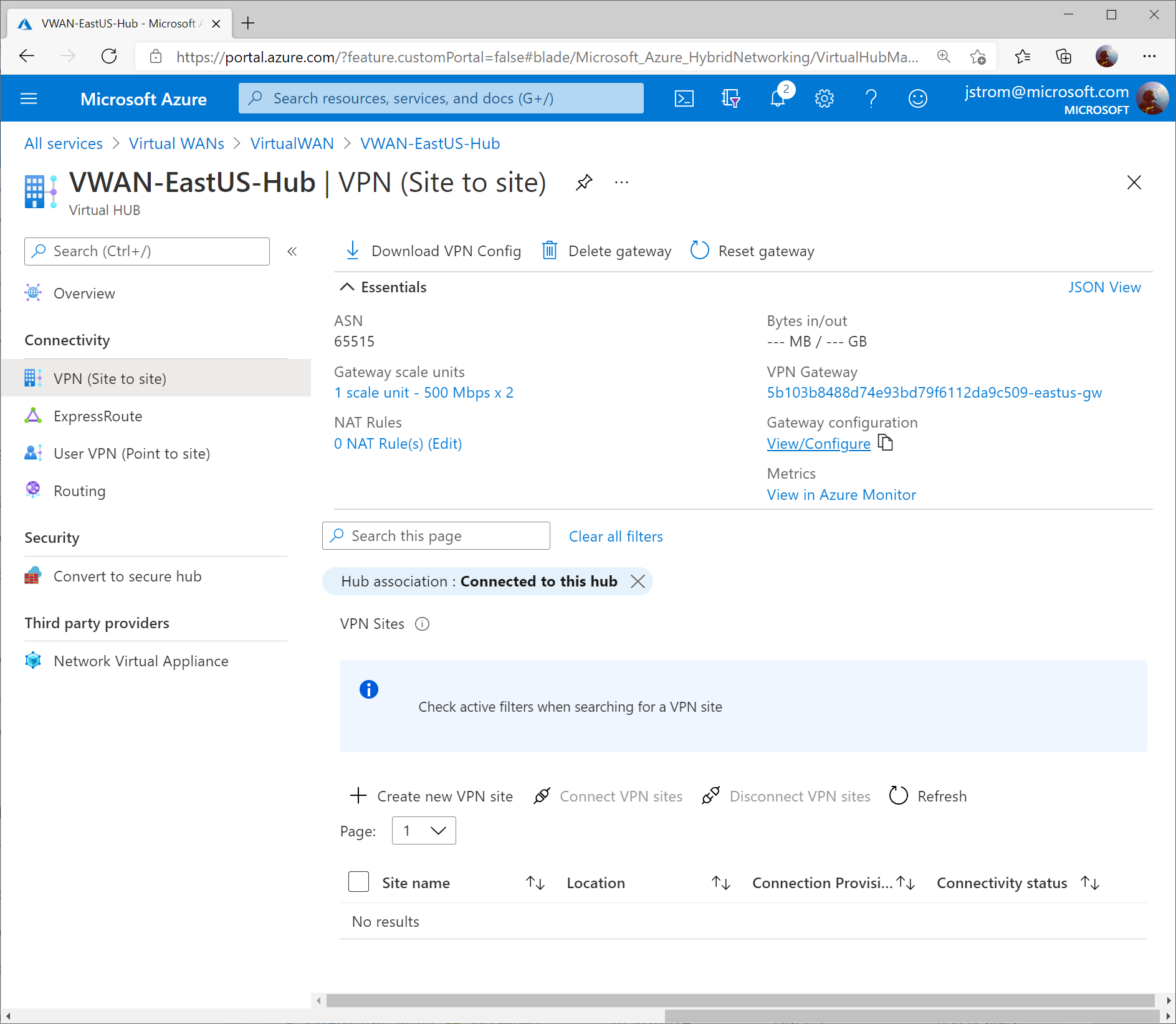
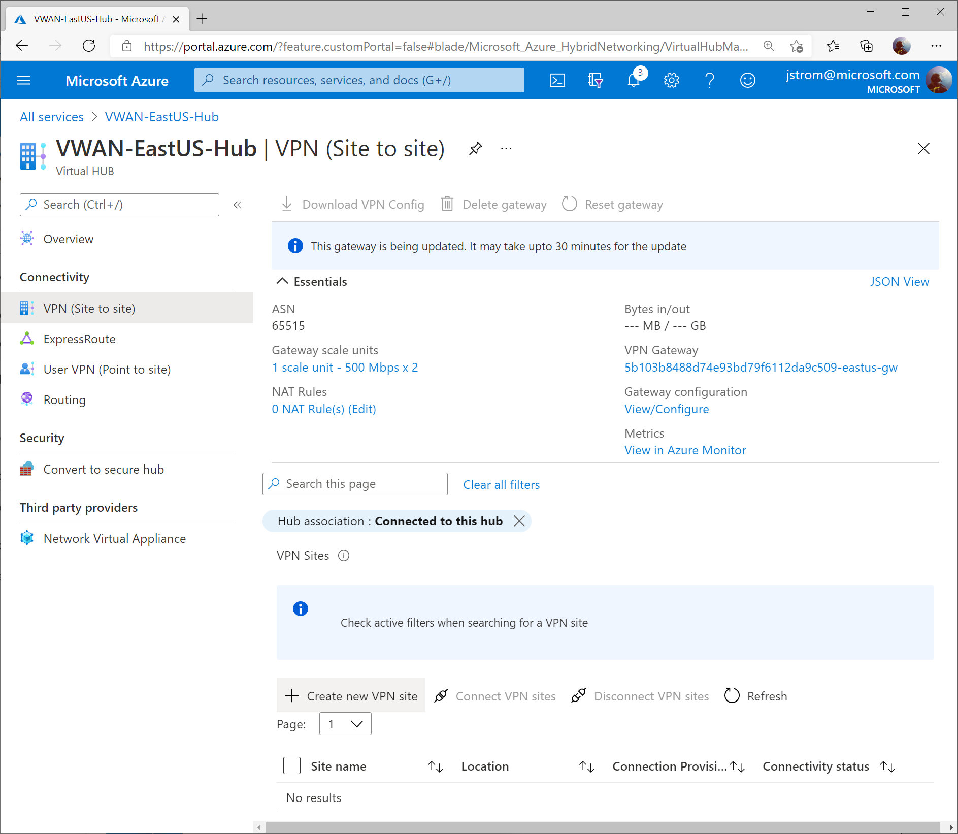
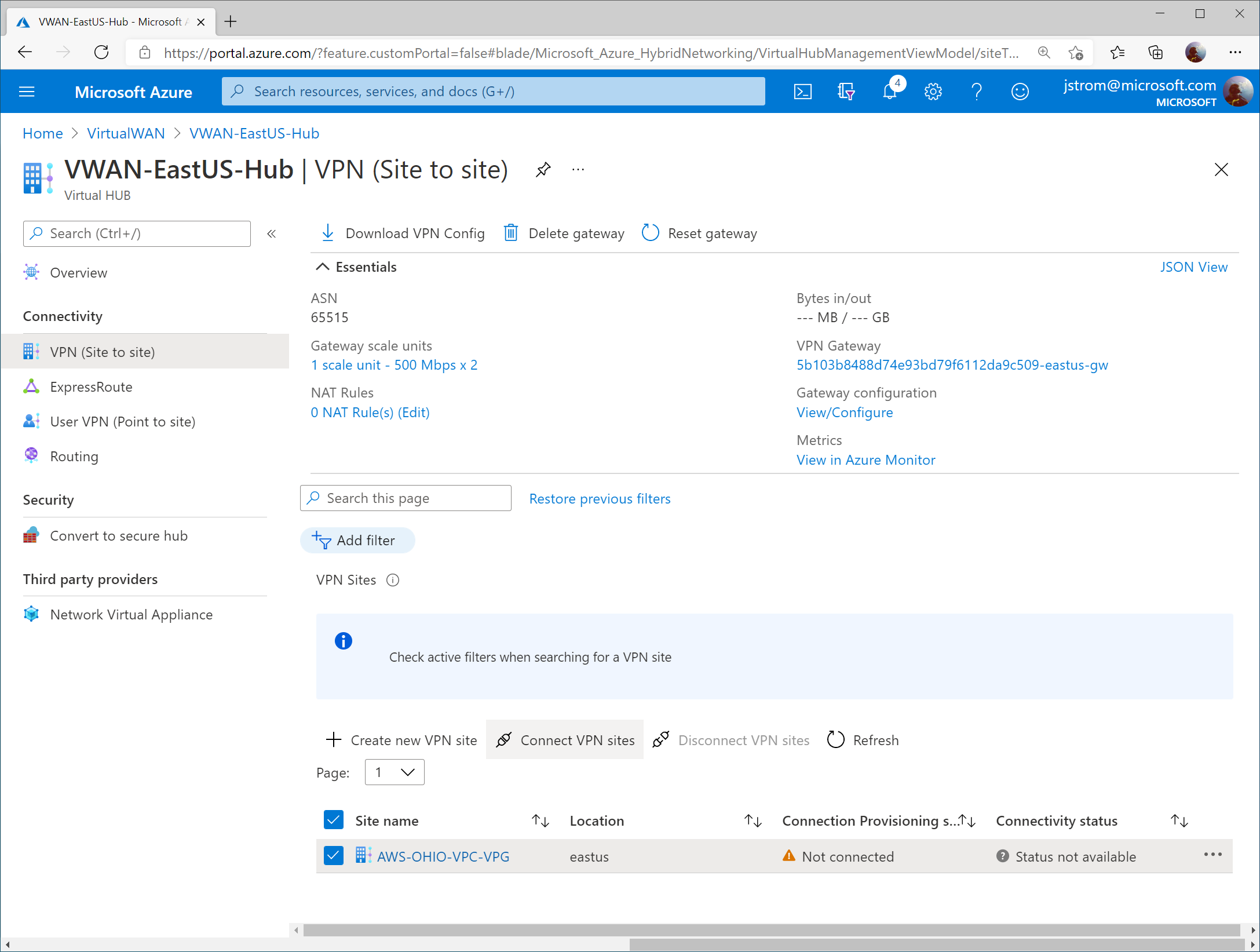
Select VPN (Site to Site) under Connectivity and then click on the View/Configure link.
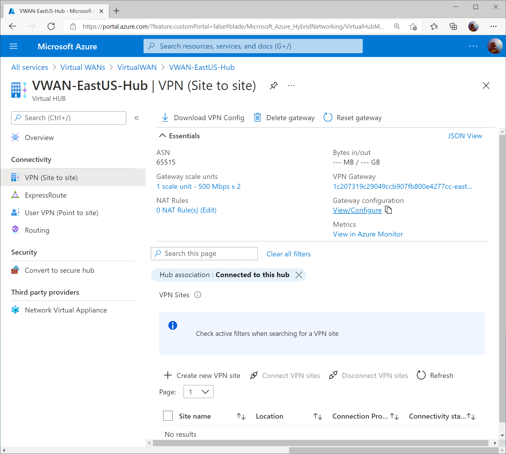
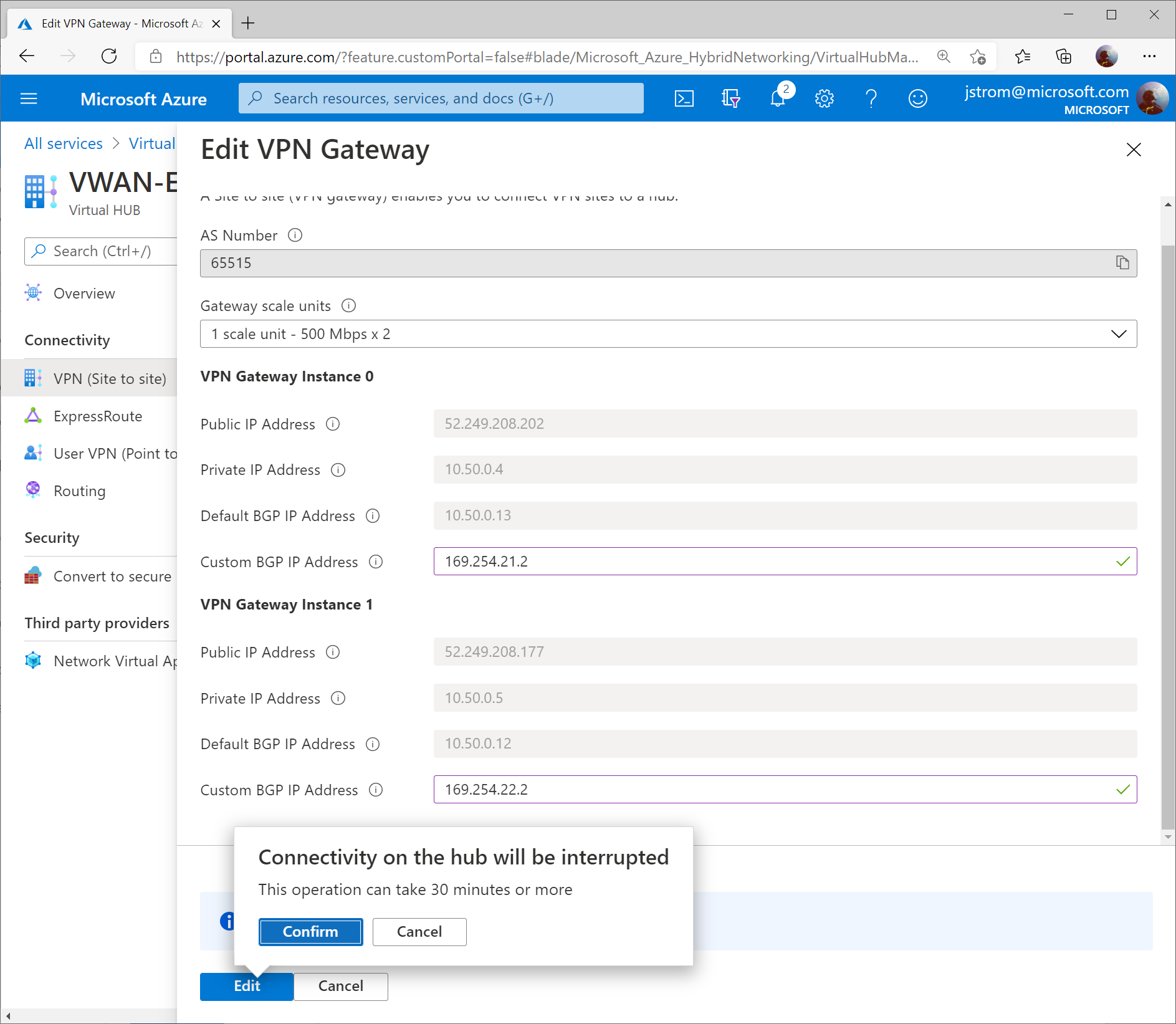
Set the Custom BGP IP addresses for each instance. Use the values below:
- VPN Gateway Instance 0: 169.254.21.2
- VPN Gateway Instance 1: 169.254.22.2
Click Edit once completed.

Configure GCP
Prerequisites
This guide assumes you have a VPC already (in my case, mine is called GCP-VPC with an address space of 10.60.0.0/16) and corresponding set of subnets for your servers.
Note: A GCP VPC is the equivalent of a VNet in Azure. One thing that is different between GCP and Azure is that in GCP you do not need to specify a subnet for your Gateways (i.e. “GatewaySubnet”).
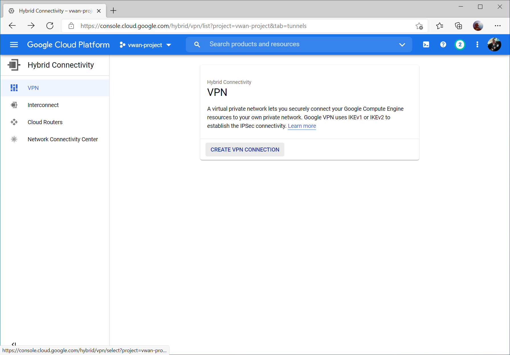
Within the GCP Console, select Hybrid Connectivity -> VPN

Click Create VPN Connection
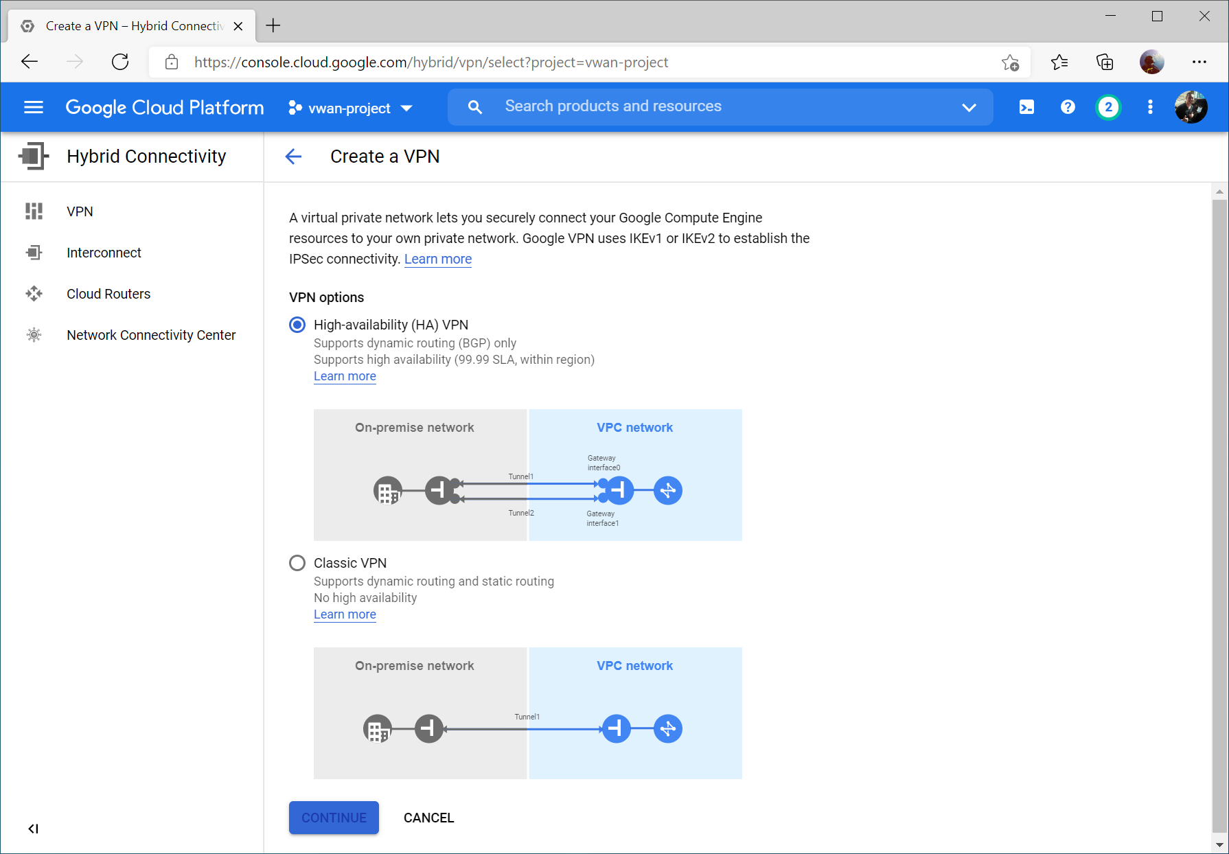
Select High-availability (HA) VPN and select Continue
Enter a name, select your VPC, and specify a region. Click Create & Continue.

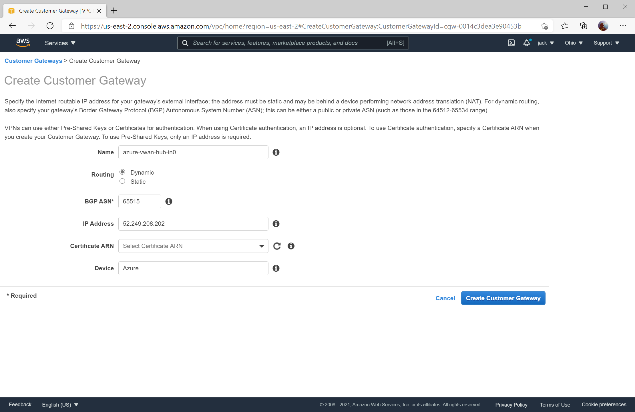
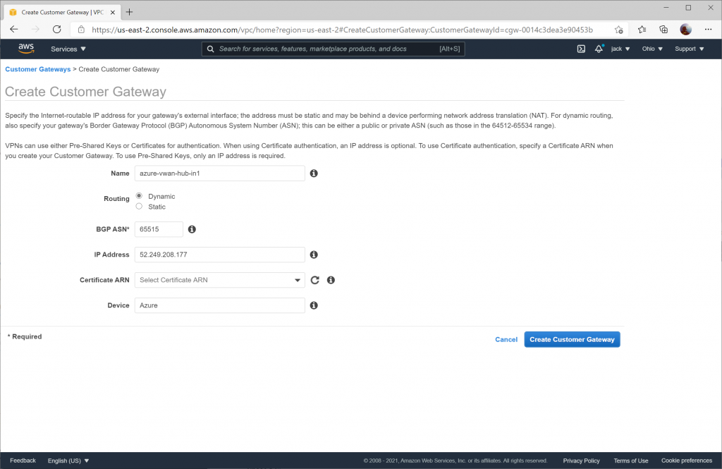
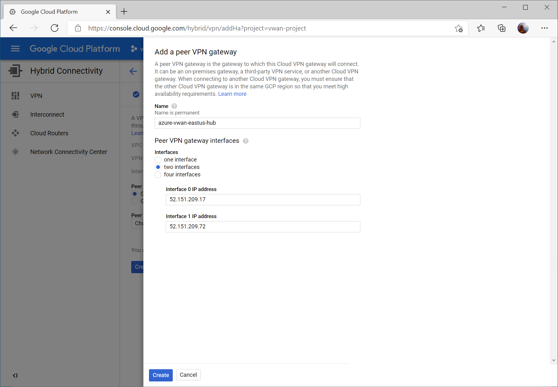
Write down your Interface public IPs (we’ll use these later) and check On-prem or Non Google Cloud for Peer VPN Gateway. Click Create & continue.
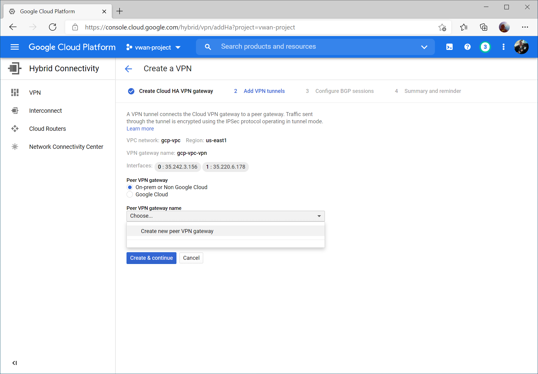
Select two interfaces and enter your Instance 0 and Instance 1 Public IP addresses from your Virtual WAN Hub’s VPN Gateway. Click Create.
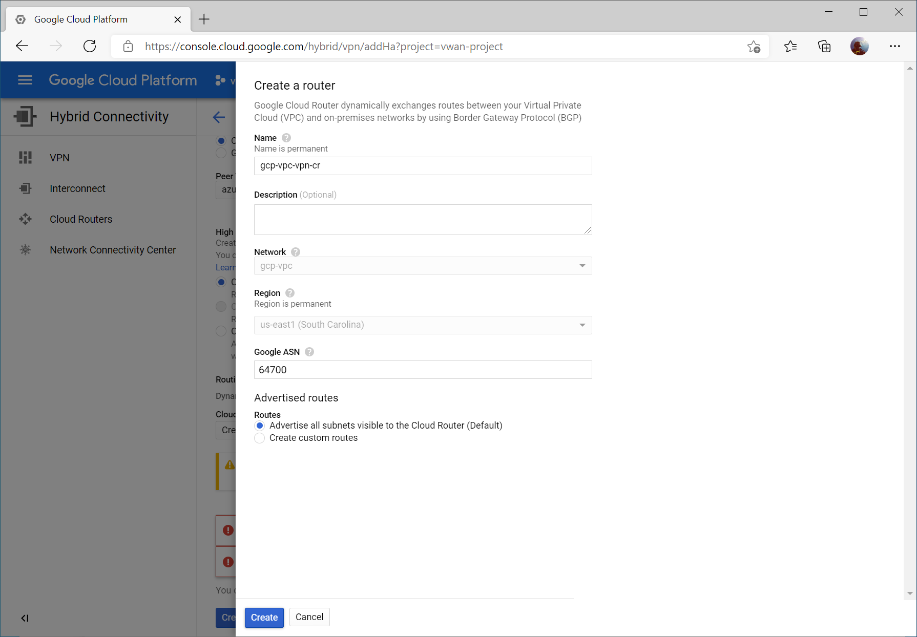
Click the dropdown for Cloud Router and select Create a new router

Enter a name and description for your router. For the ASN, enter a unique ASN to use (I used 64700 to differentiate from Azure as well as the ASN I used in the AWS example (which was 64512)). You can specify any supported ASN for this, however I would recommend against using 65515 specifically as this is reserved by Azure’s VPN Gateways.
Note: Google ASN must be an integer between 64512 and 65534 or between 4200000000 and 4294967294 or 16550
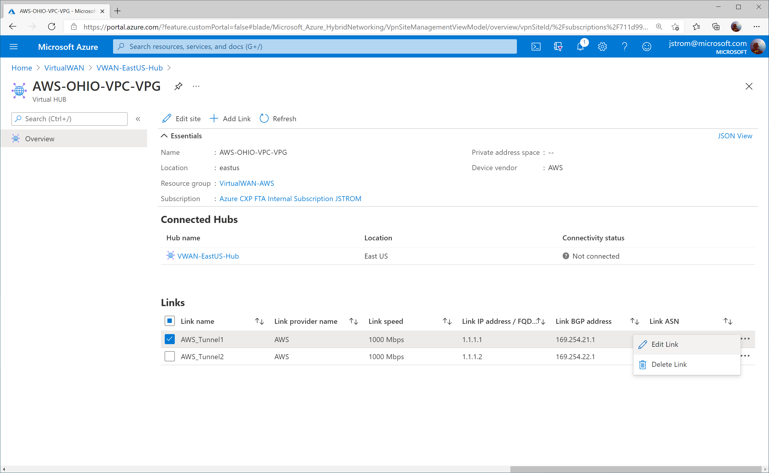
Click the pencil icon to modify the first VPN tunnel.
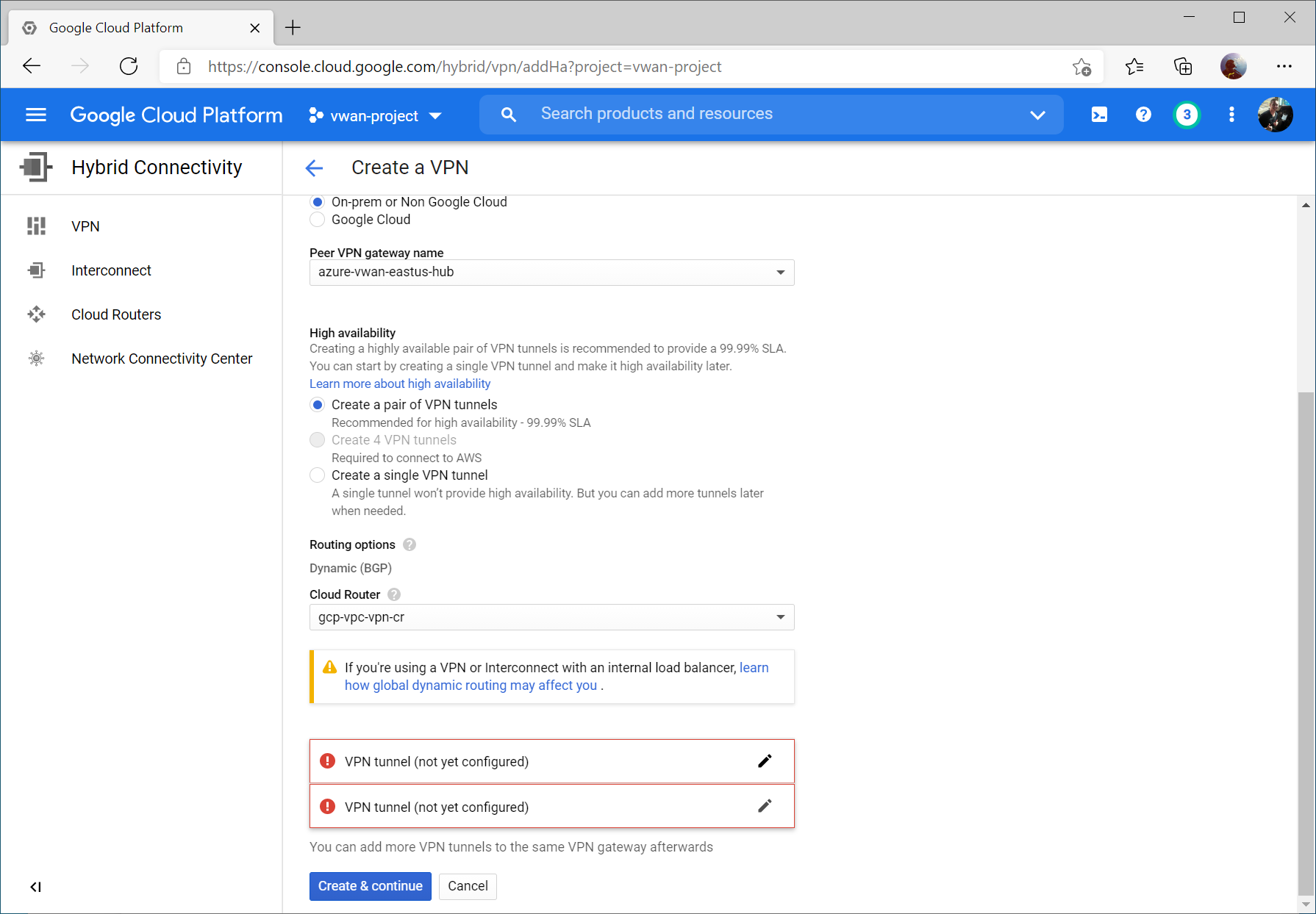
Select the instance 0 VPN Gateway interface, enter a name, set the IKE version to IKEv2, enter a pre-shared key, and click Done.

Repeat the same steps for the second VPN tunnel, specifying instance 1 VPN Gateway interface, enter a name, set the IKE version to IKEv2, enter a pre-shared key, and click Done and then Create & continue.

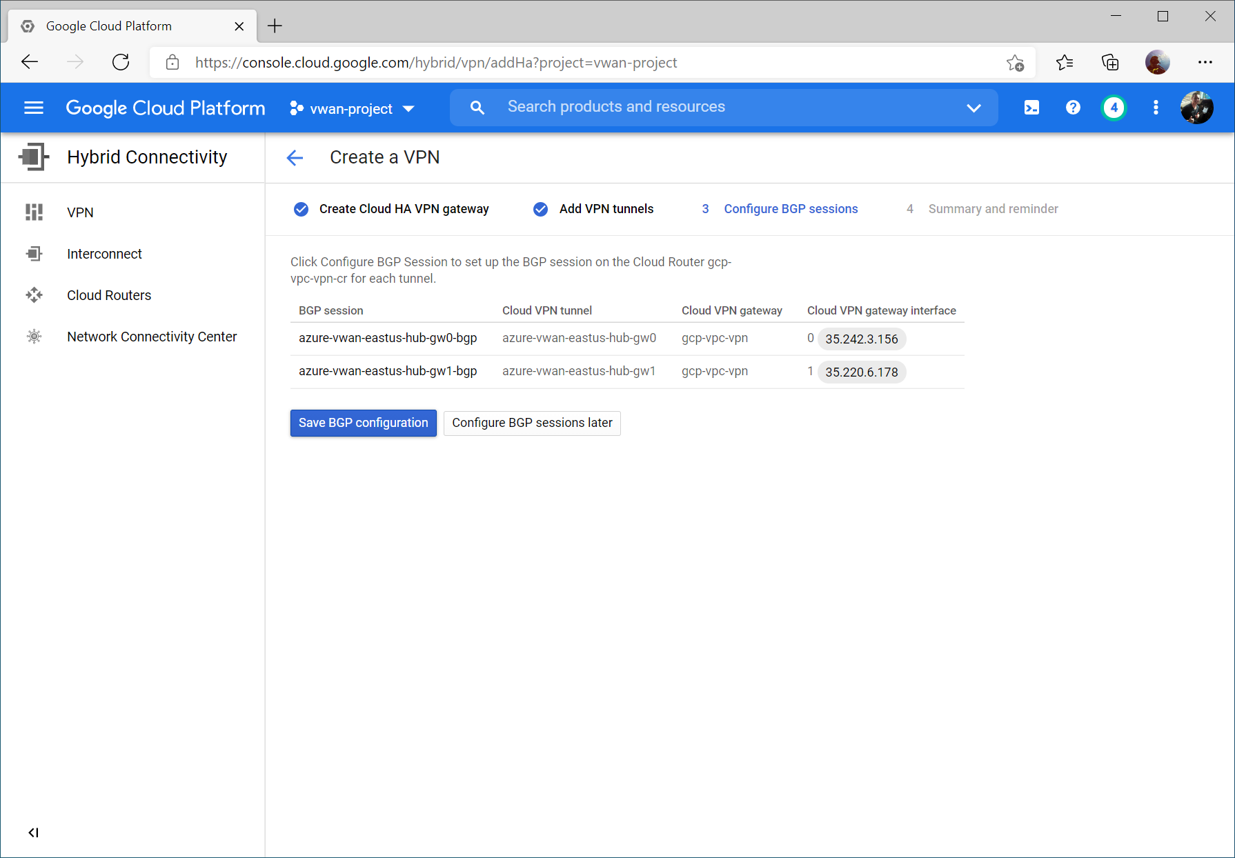
Click the Configure button for the first BPG session.
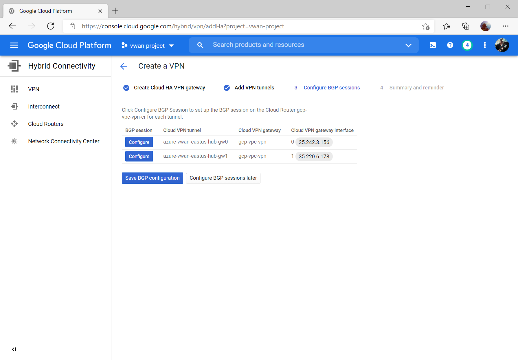
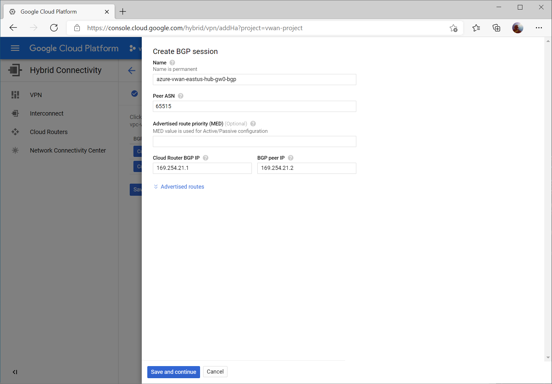
Enter a name for the first BGP peer connecting to instance 0 gateway on Virtual WAN.
Specify Peer ASN of 65515 (this is Azure VWAN’s BGP ASN), specify 169.254.21.1 for Cloud Router BGP IP and 169.254.21.2 as BGP peer IP (Azure VWAN’s BGP Peer IP). Click the Save and continue button.
Click the Configure button and enter a name for the first BGP peer connecting to instance 1 gateway on Virtual WAN.
Specify Peer ASN of 65515 (this is Azure VWAN’s BGP ASN), specify 169.254.22.1 for Cloud Router BGP IP and 169.254.22.2 as BGP peer IP (Azure VWAN’s BGP Peer IP).

Click the Save BGP configuration button.
Configure Azure Virtual WAN VPN Site
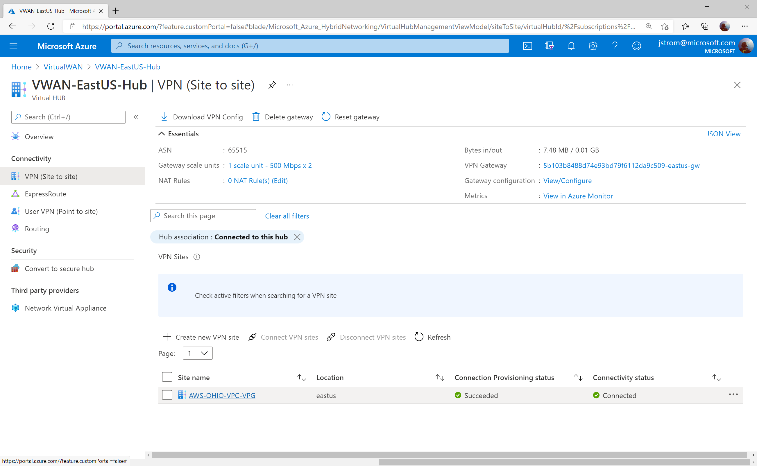
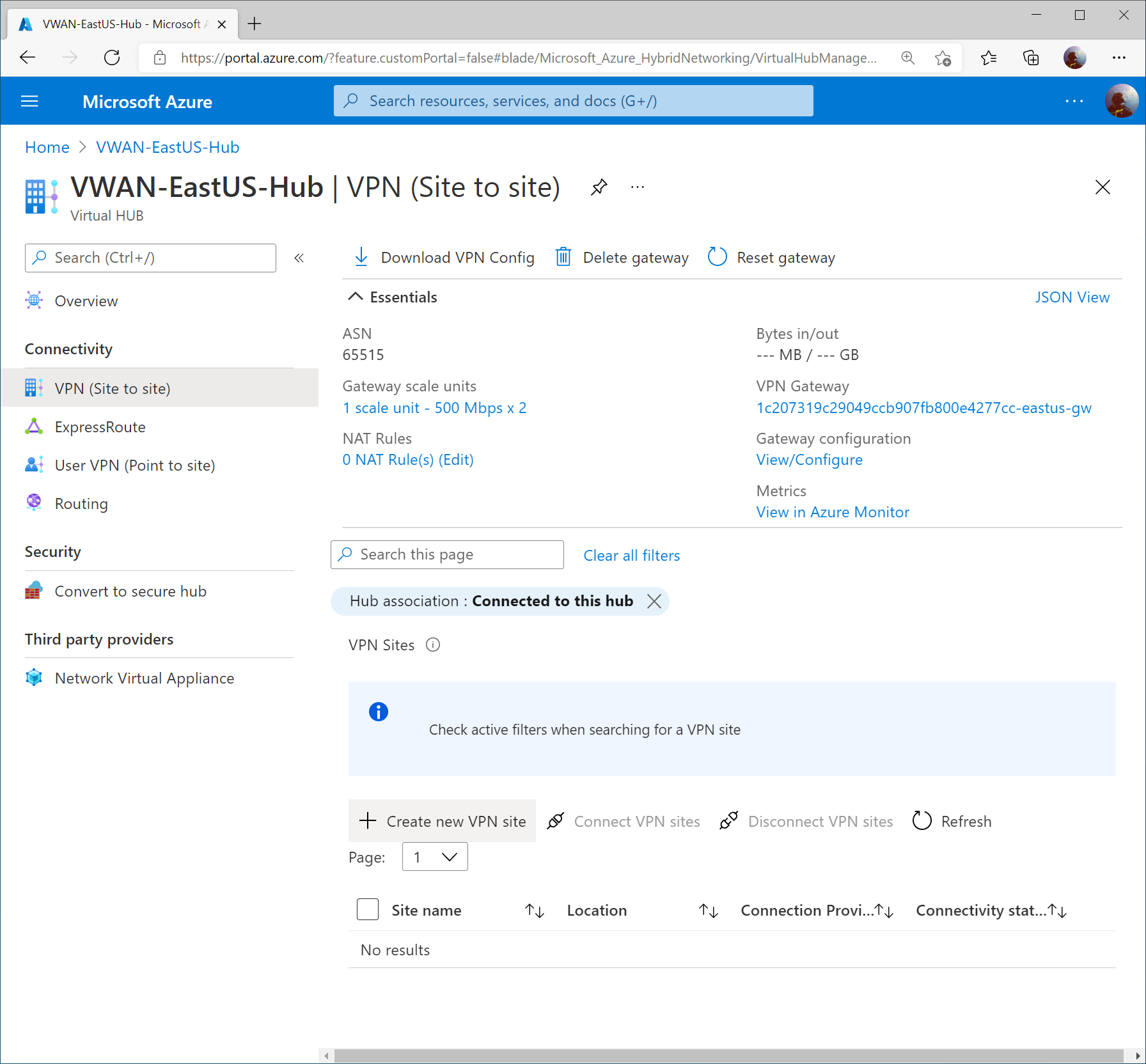
On the Virtual WAN hub, select VPN (Site to site) and click + Create new VPN site
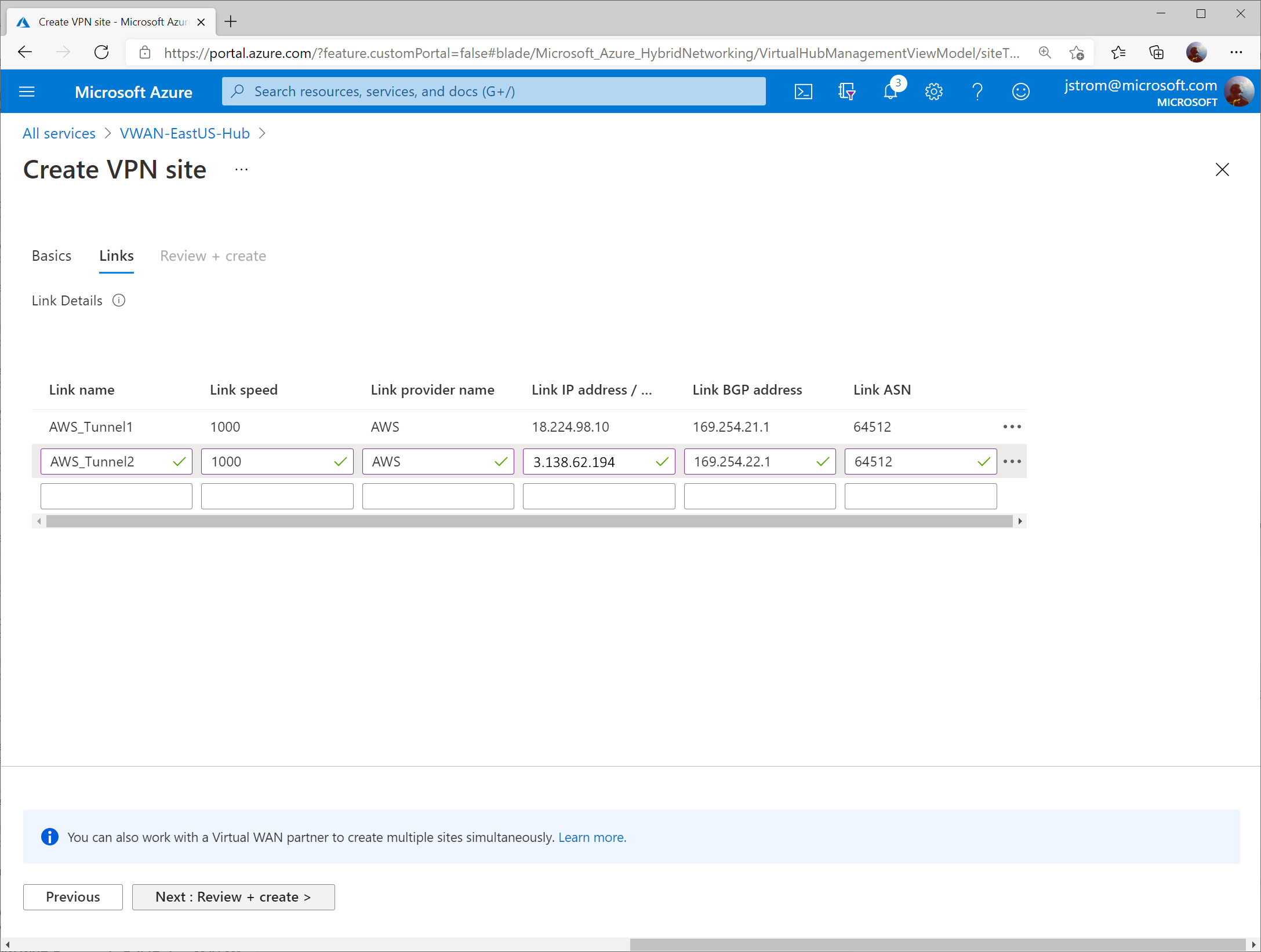
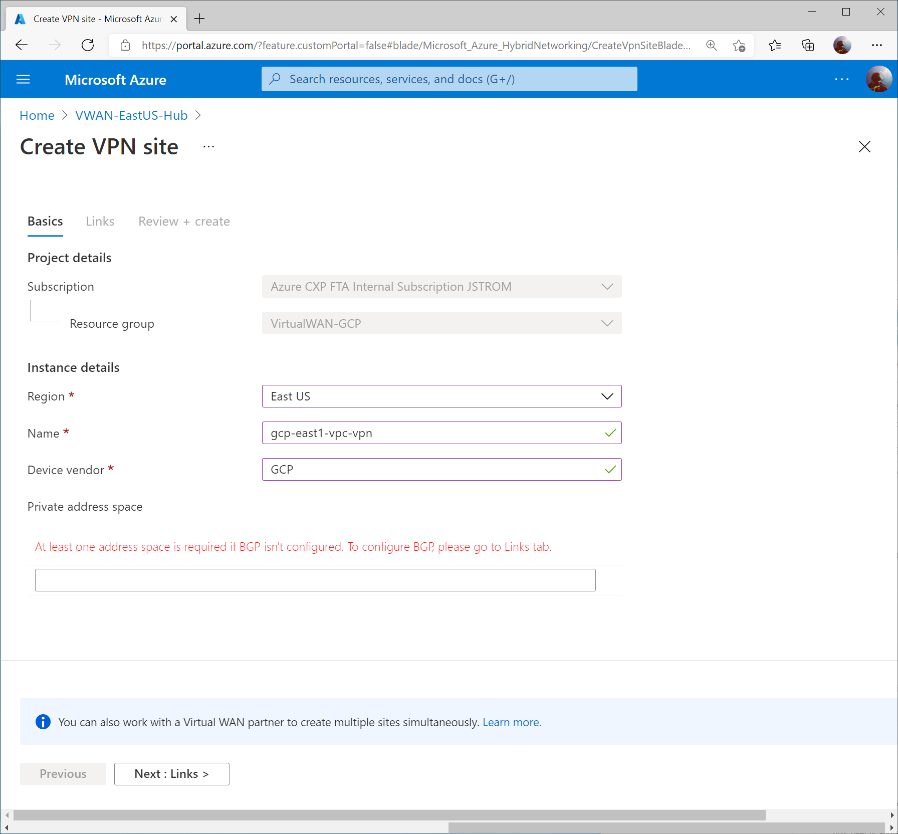
Specify a name for the VPN connection, enter GCP for vendor, and click Next : Links >
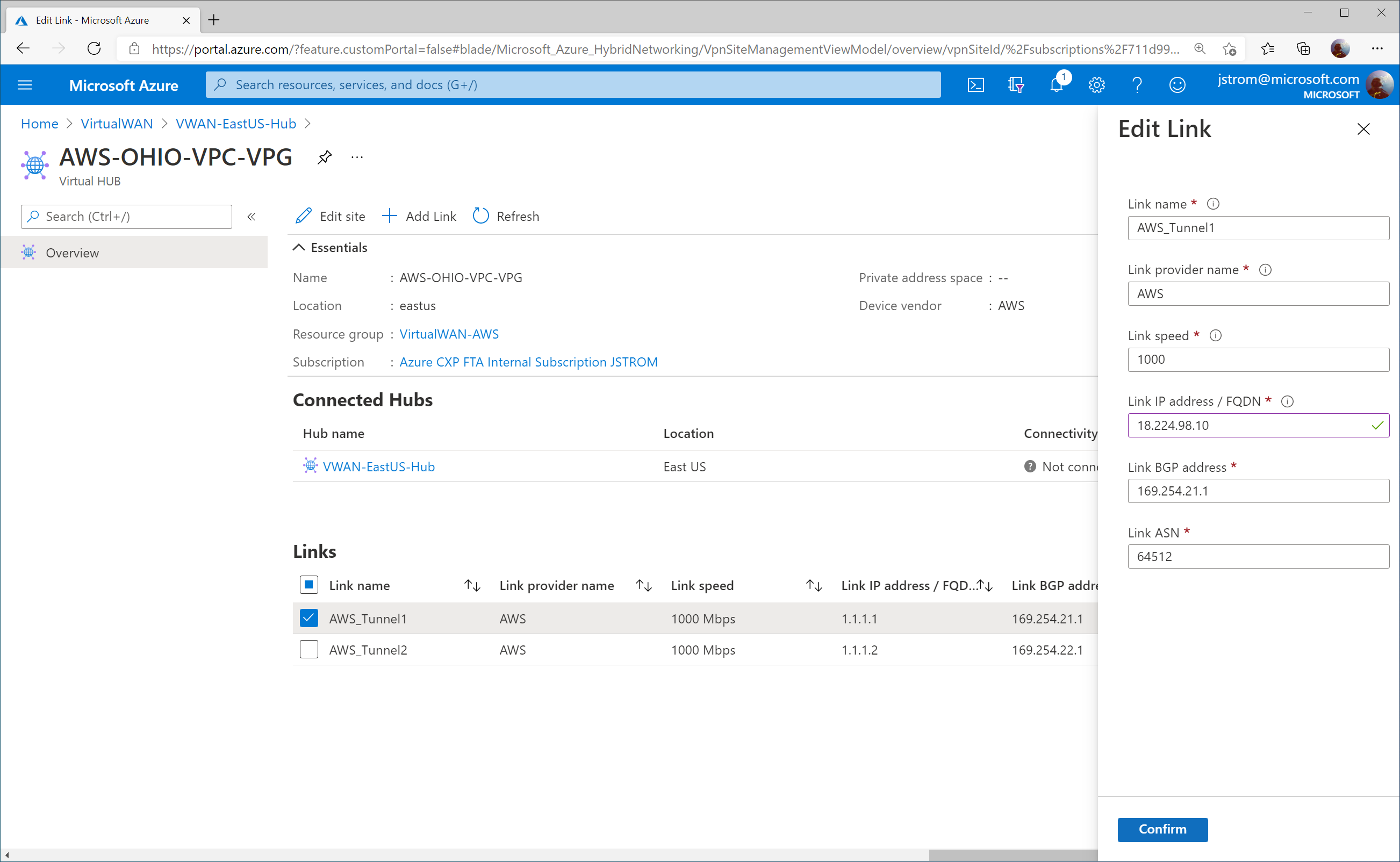
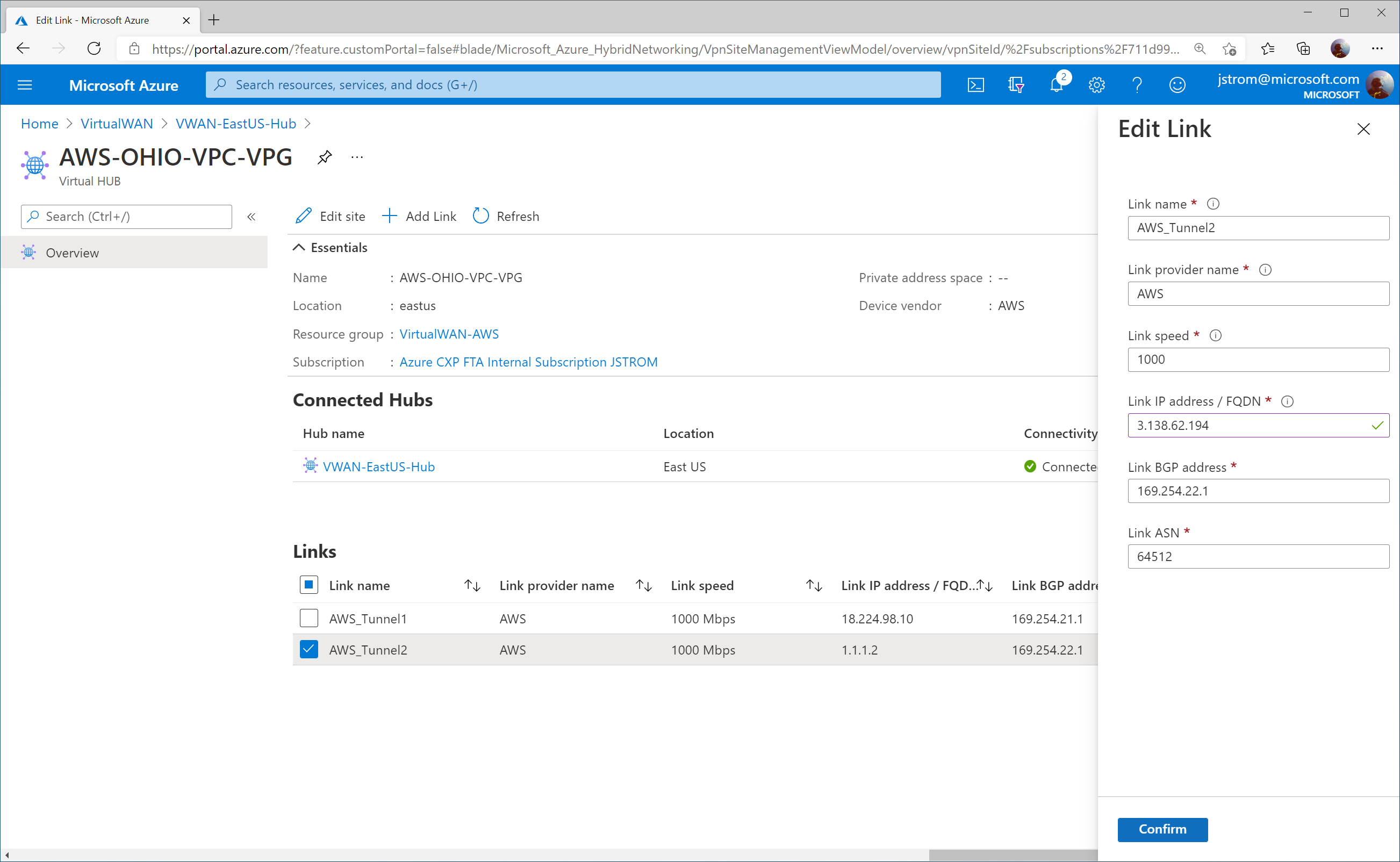
Specify the following values to define each VPN tunnel that should be created to connect to GCP’s VPN interfaces.
Note: I entered 1000 for the link speed as a placeholder, but that doesn’t mean the connection will be throttled down to 1Gbps.
- First Link:
- Link Name: gcp-east1-vpc-vpn-int0
- Link Speed: 1000
- Link provider name: GCP
- Link IP address: <GCP VPN Interface 0 Public IP>
- Link ASN: 64700
- Second Link:
- Link Name: gcp-east1-vpc-vpn-int1
- Link Speed: 1000
- Link provider name: GCP
- Link IP address: <GCP VPN Interface 1 Public IP>
- Link ASN: 64700

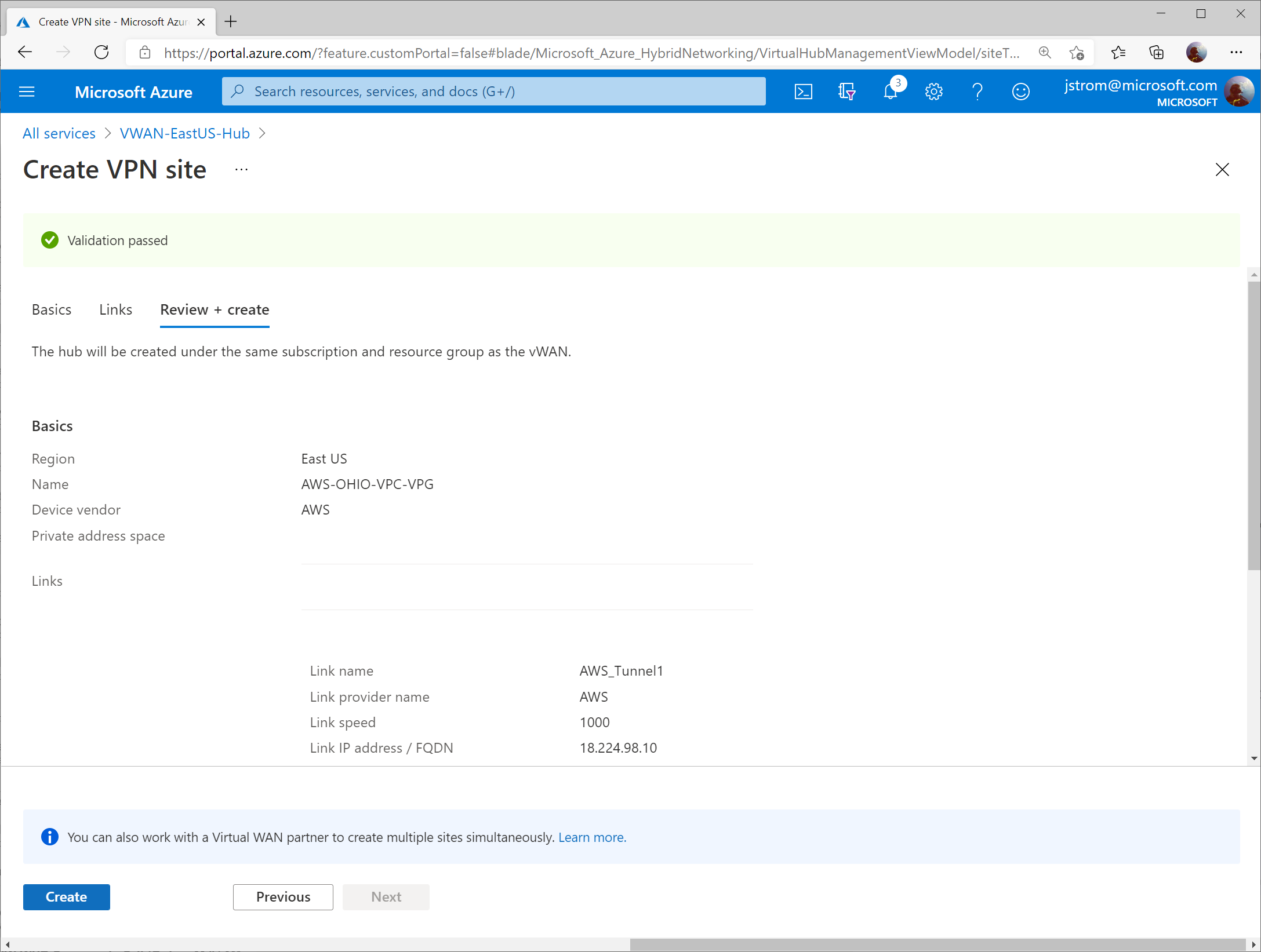
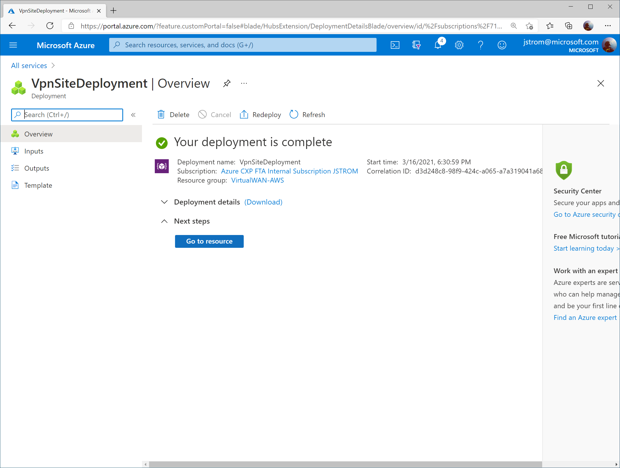
Click Create

Configure Virtual WAN VPN Connection
Once the Virtual WAN Hub has been created, click the Menu icon and select All services.
Search for Virtual WAN and select Virtual WANs.
Select your Virtual WAN resource.
Click on Hubs under Connectivity and select your Virtual WAN Hub.
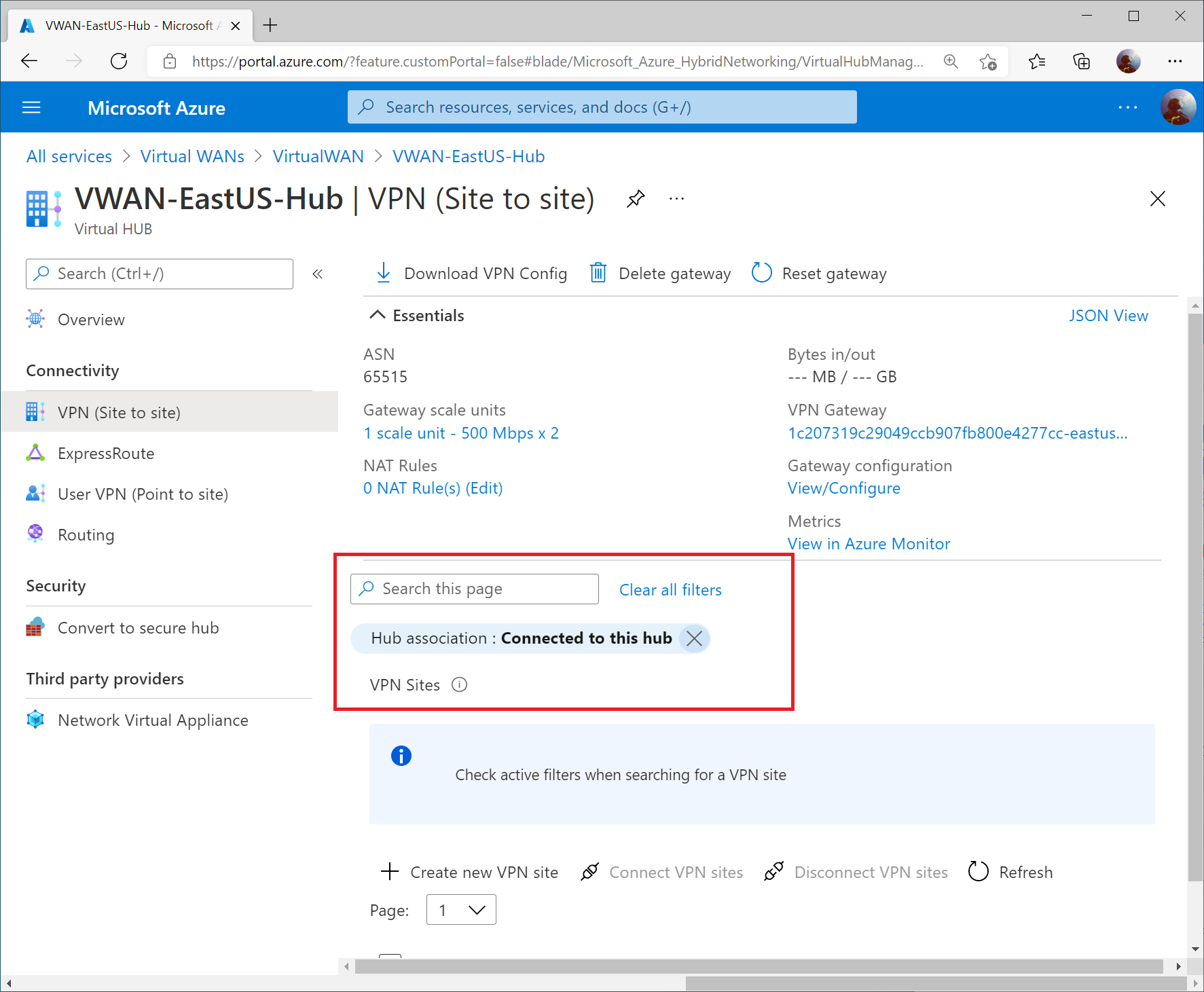
Select VPN (Site to Site) under Connectivity and then click on the X to remove the Hub association filter.
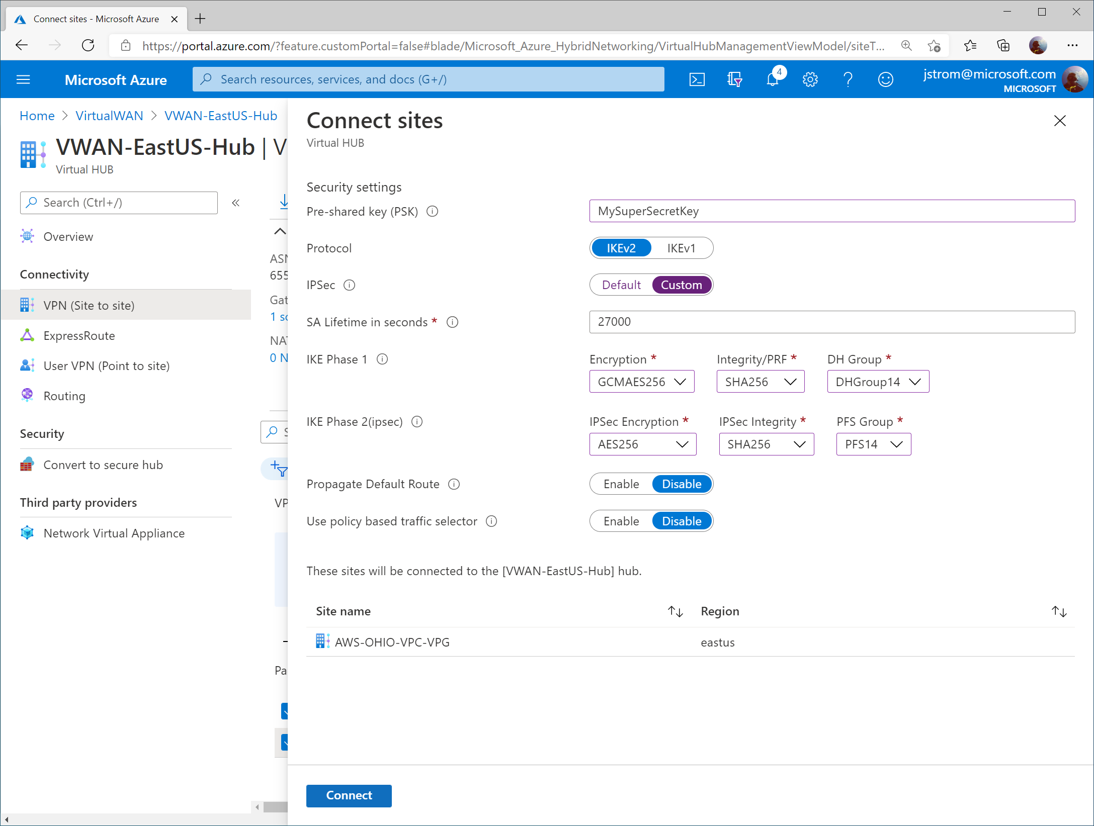
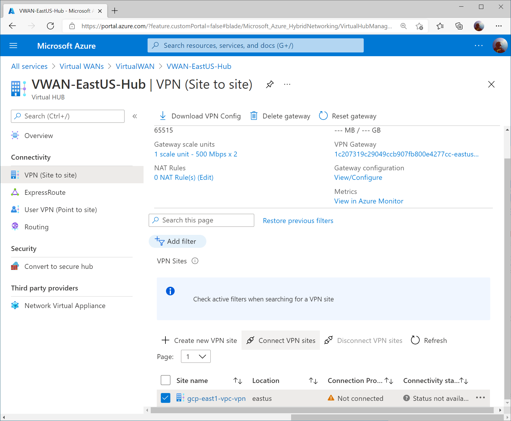
Check the box for your VPN site and click Connect VPN sites
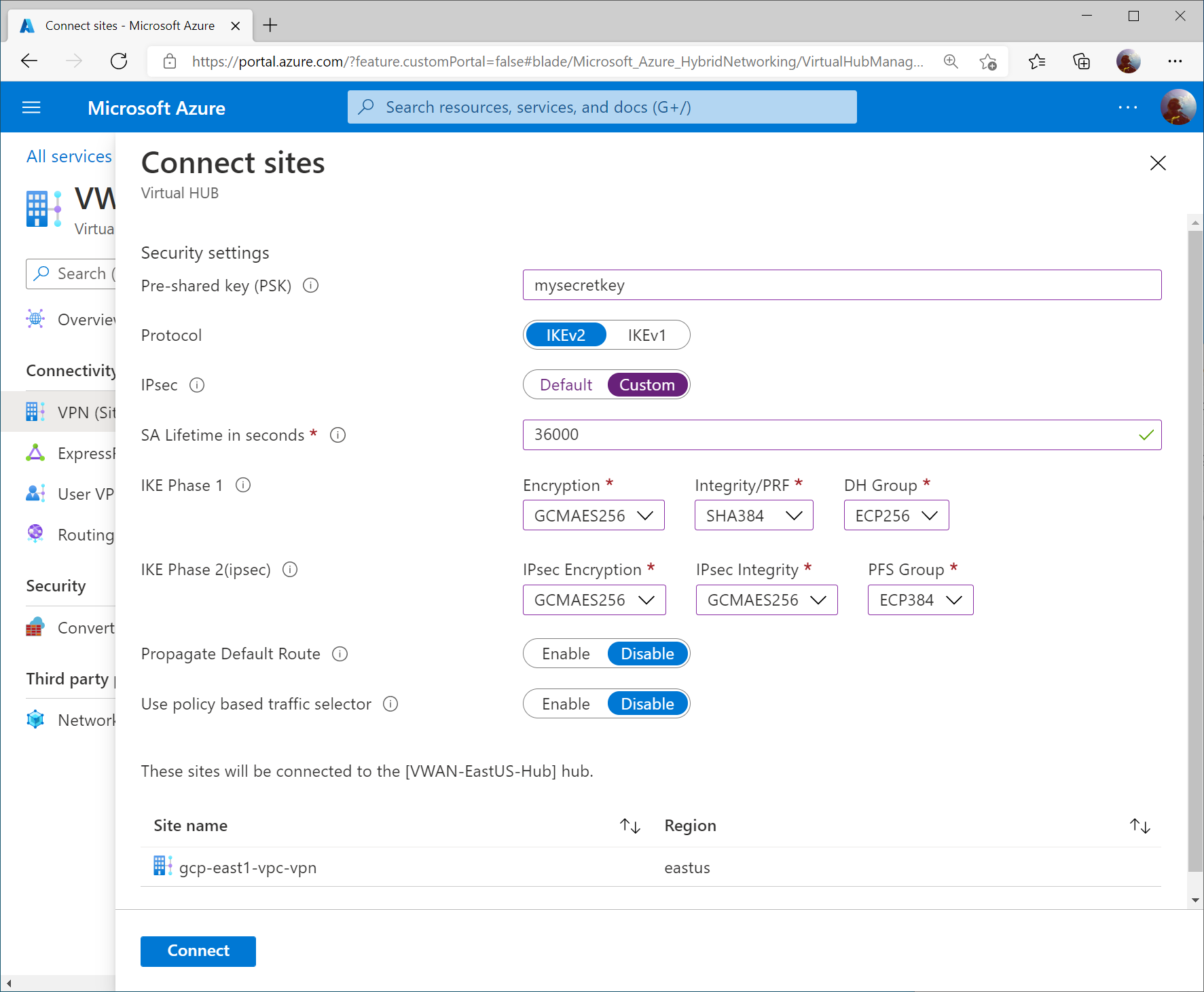
Specify the following information:
- Pre-shared key (PSK): <use the same one you specified in GCP>
- Protocol: IKEv2
- IPsec: Custom
- SA Lifetime in seconds: 36000
- Phase 1 (IKE):
- Encryption: GCMAES256
- Integrity/PRF: SHA384
- DH Group: ECP256
- Phase 2 (IPSec):
- Encryption: GCMAES256
- IPSec Integrity: GCMAES256
- PFS Gropu: ECP384
- Propagate Default Route: Disable
- Use policy based traffic selector: Disable
Click Connect.
Note: Here is the link of Supported IKE ciphers for GCP.
Verify Connectivity
From the Azure Side, we will review three different areas to validate connectivity and propagation of routes via BGP.
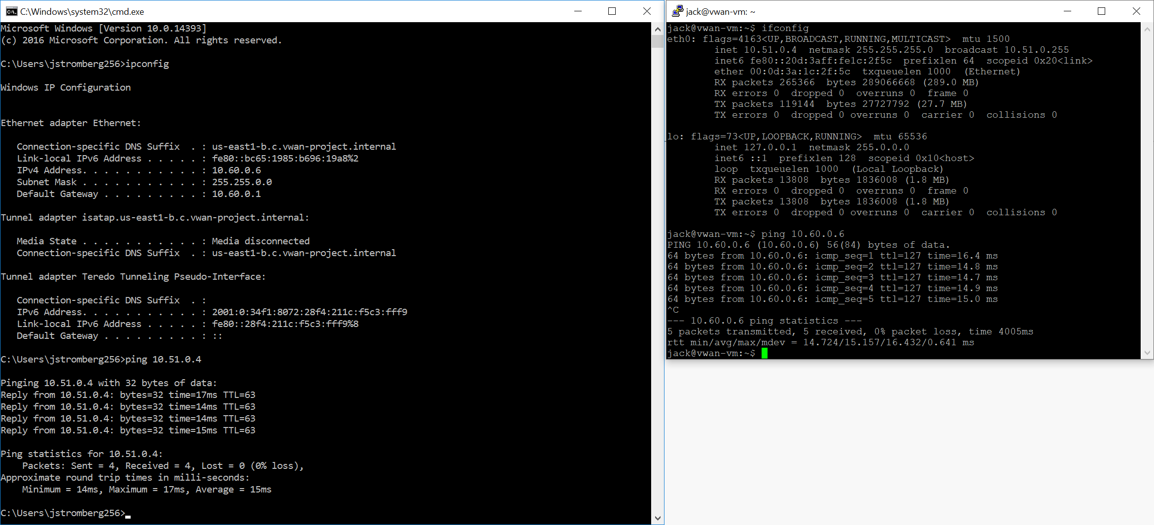
Note: I connected a virtual network to the Virtual WAN Hub to show further configuration. In this case, you’ll see an additional IP address space of 10.51.0.0/16, which defines my connected VNet.
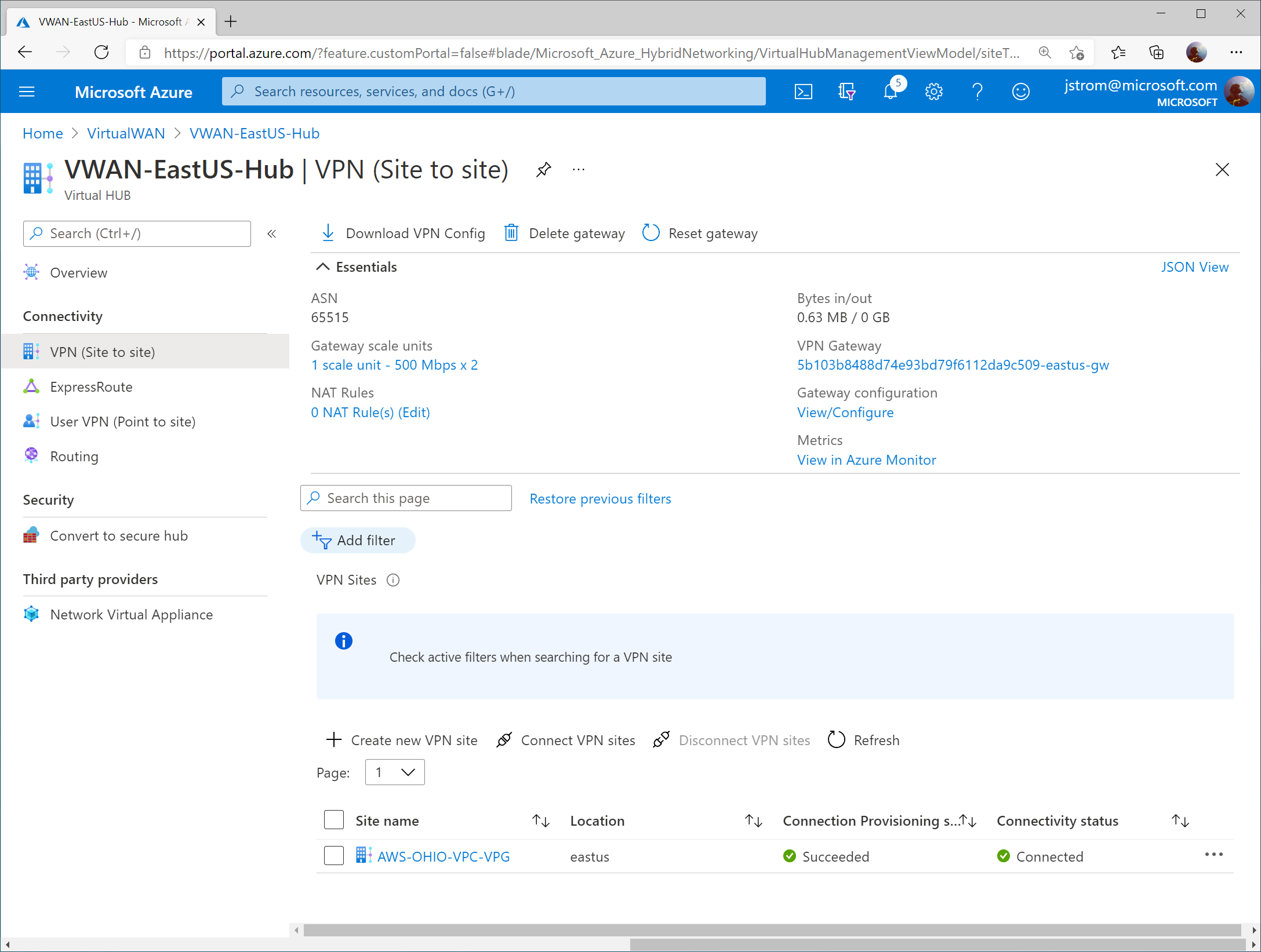
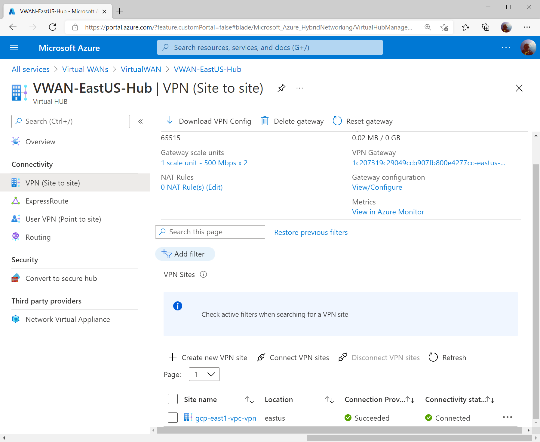
On the Azure Side, you should see the VPN Site’s Connectivity status change to Connected on the VPN (Site to site) blade of your Virtual WAN hub.
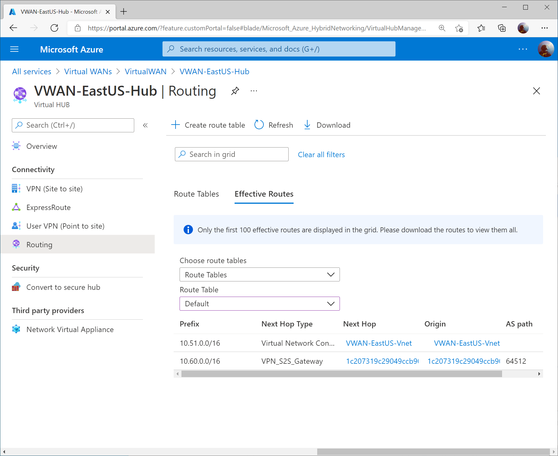
On the Routing blade, the Effective Routes will show you the learned VPC address space from GCP (10.60.0.0/16)
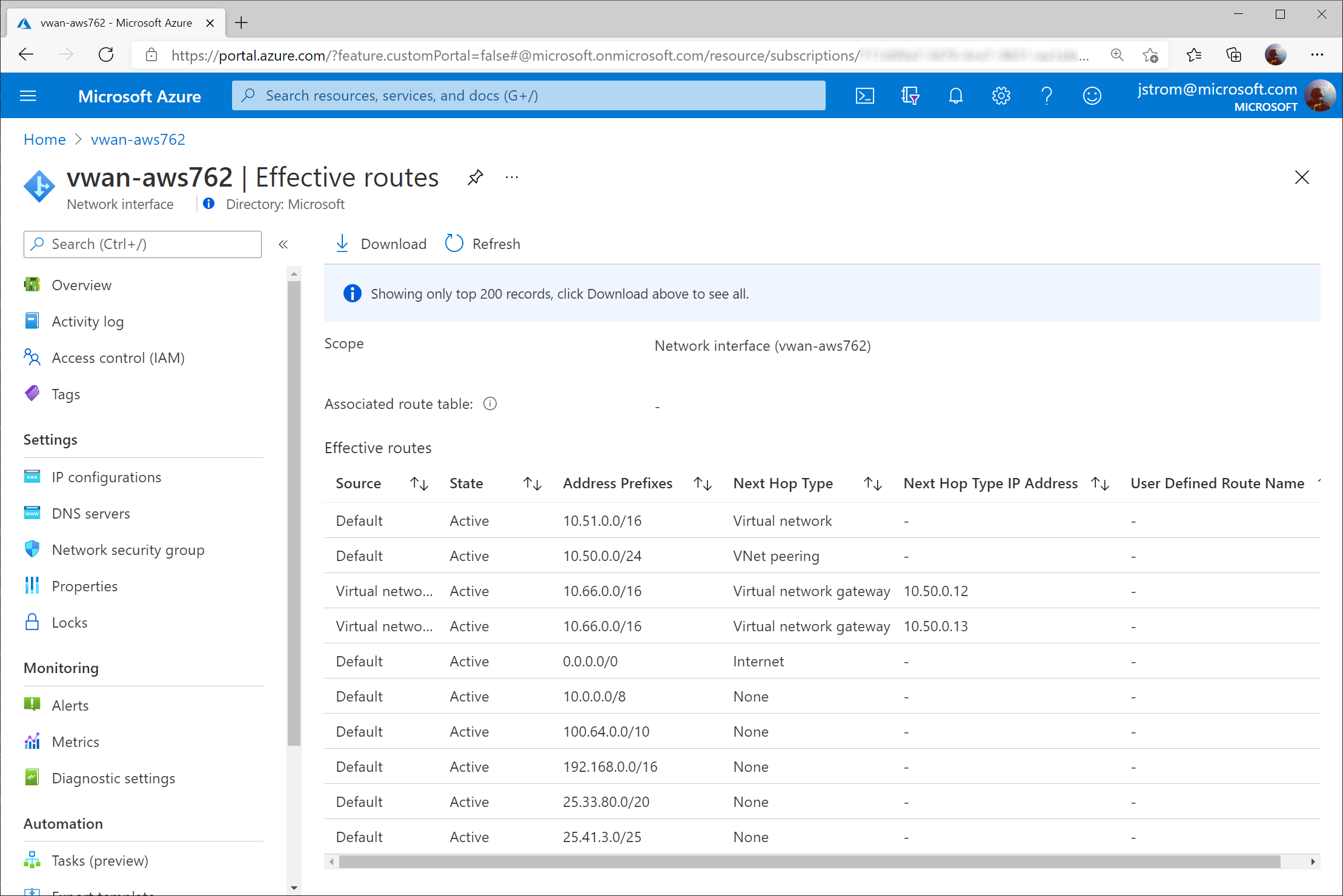
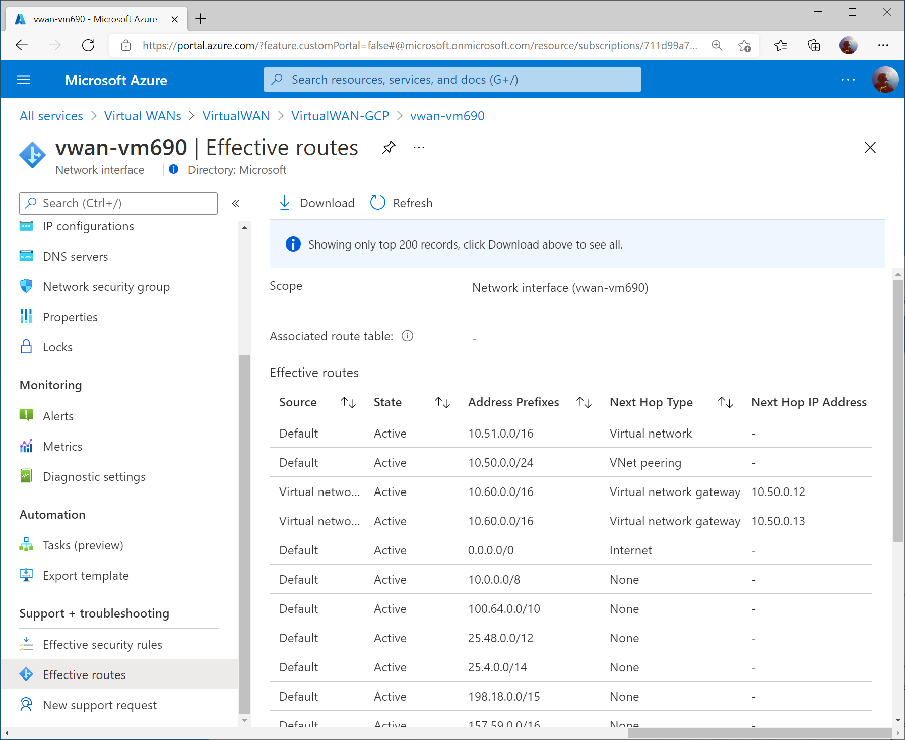
On a virtual machine in a connected VNet to the Virtual WAN Hub, you can pull the Effective Routes. Here I see the 10.60.0.0/16 route learned from both Instance 0 and Instance 1 gateways from the Virtual WAN Hub.
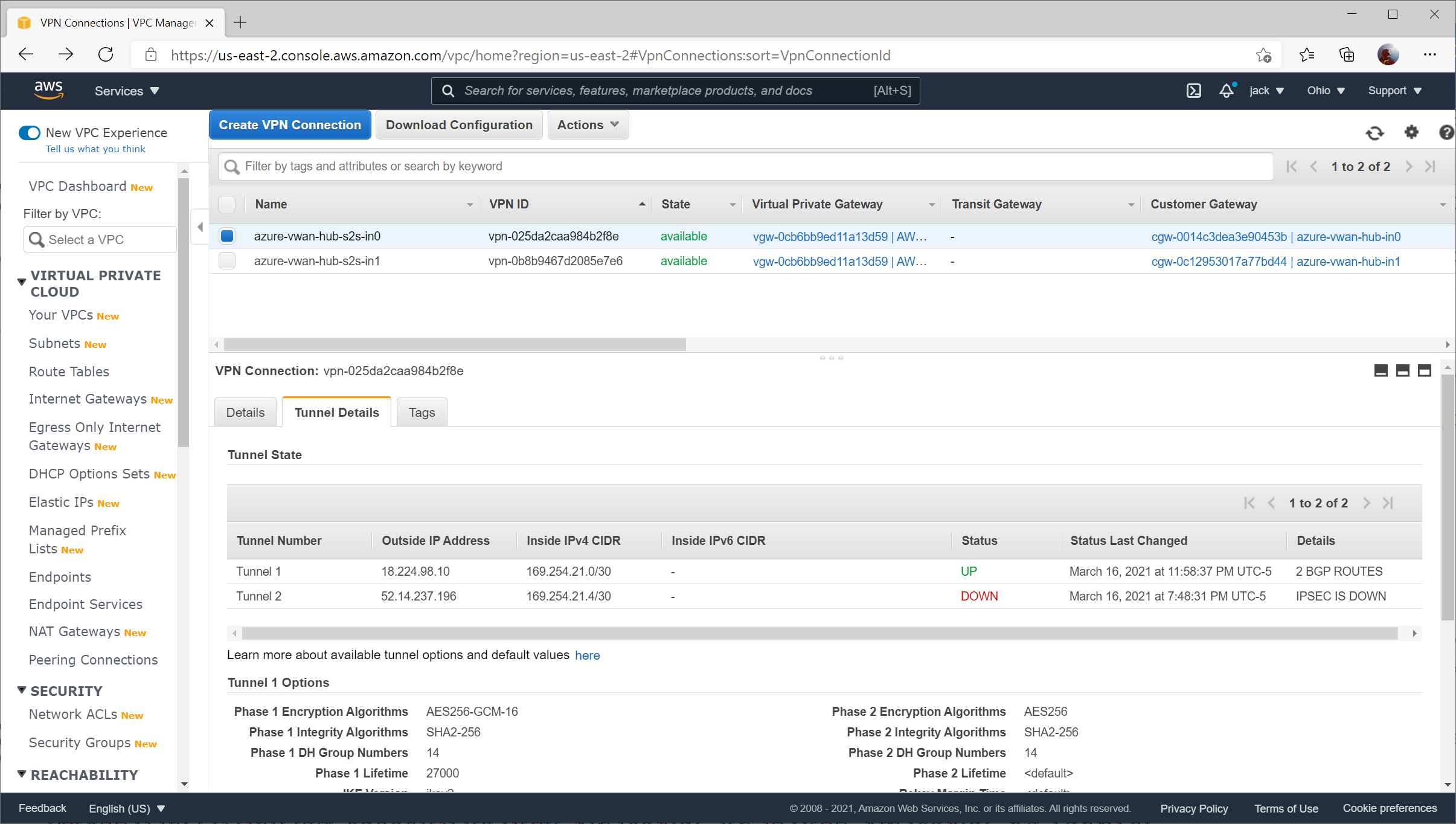
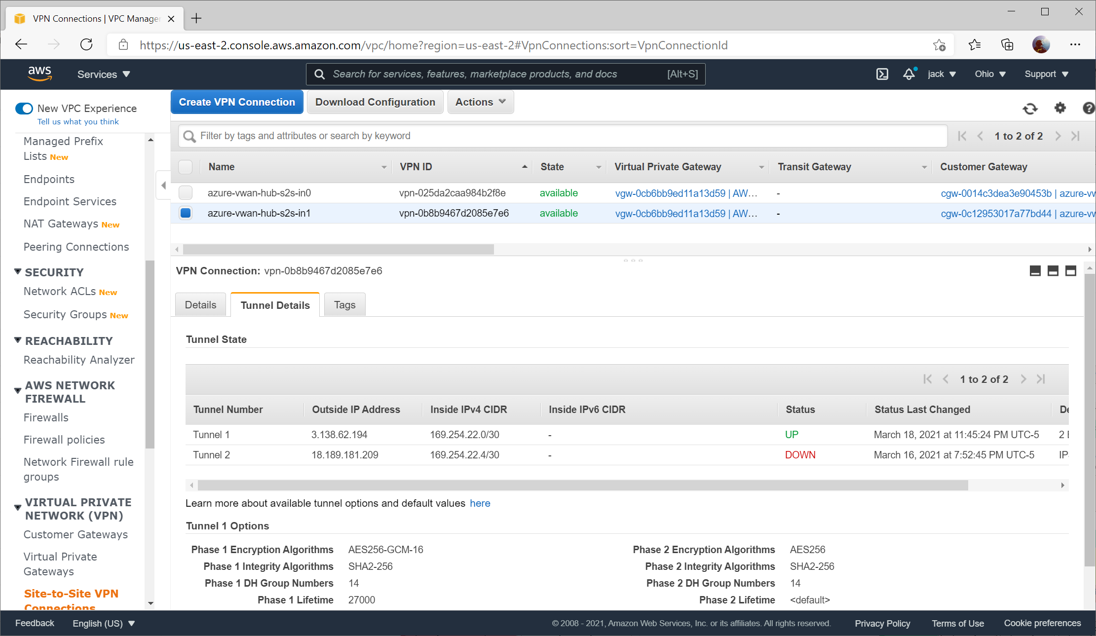
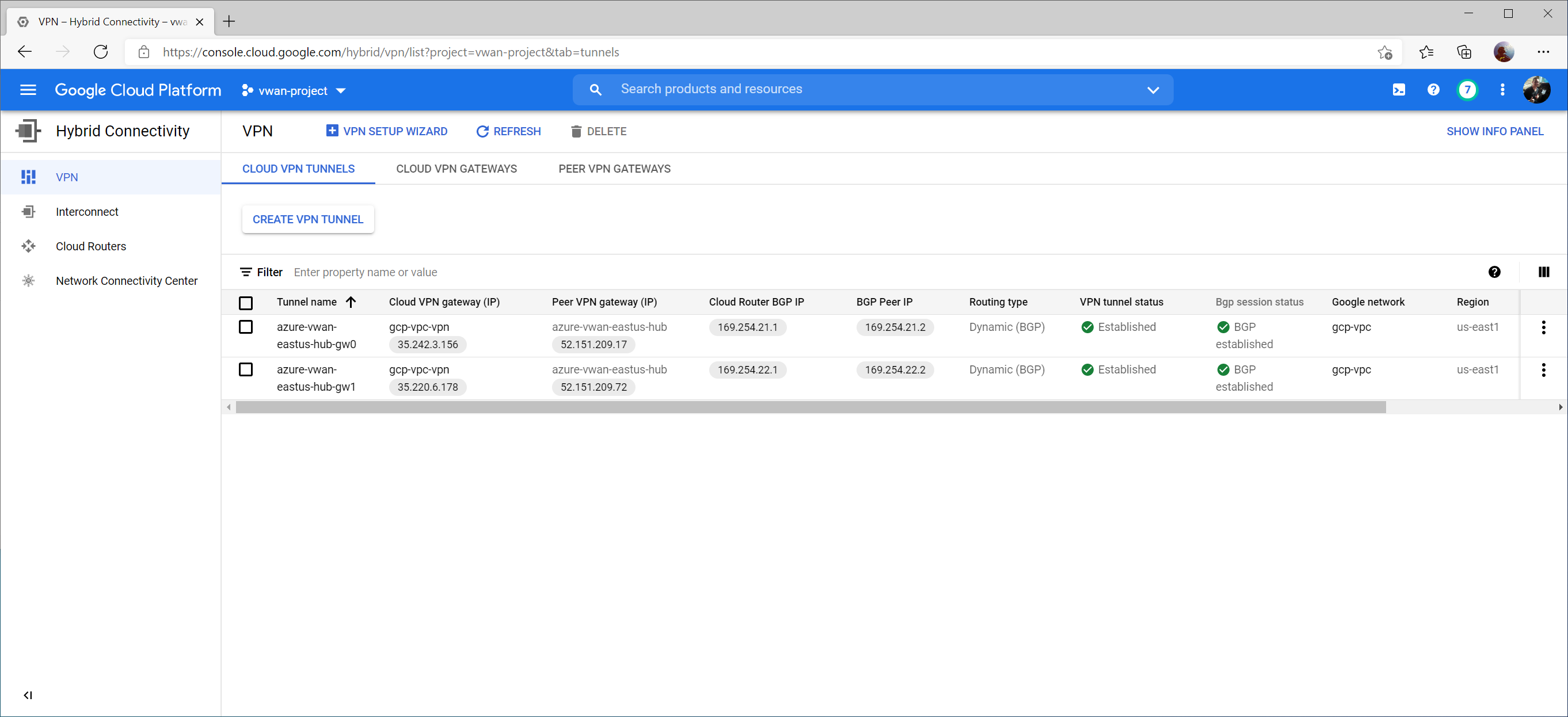
From the GCP Side, we can see the VPN tunnel status as well as Bgp session status now Established and Green on the Hybrid Connectivity -> VPN -> Cloud VPN Tunnels section.
If we switch over to Hybrid Connectivity -> Cloud Routers -> and select View on the logs column

Further, if creating a VM (instance) in GCP, you can view the Firewall and Route details to confirm you see the learned routes from the gateway (in our case, we see 10.51.0.0/16 and 10.50.0.0/24 learned from both BGP Peers):

Huzzah! Traffic! 🙂