Category Archives: Raspberry Pi

Building My Own GPS Stratum-1 Time Server on a Raspberry Pi

Building My Own GPS Stratum-1 Time Server on a Raspberry Pi

Time silently hums away in the background, affecting everything we do today. Wake up, go to work, go to an appointment; all happen at specific times. Computers are no different, constantly logging time in logs, showing time in applications, and used for scheduling. In general, no one really cares about time because it's typically "accurate enough" for most tasks. Most computers just automatically have the correct time and are accurate down to a second or so, with most people perfectly content that it's technically approximately right. That being said, I'm neurotic and want nuclear-science-lab accuracy, knowing precisely what time it is.

While pool.ntp.org is a fantastic source of time, why settle when you can have sub-microsecond precision? No one is going to have a good time when you're technically having a bad time.

For this project, I wanted to see how precise time can be in my house, owning it end to end — no leaning on someone else's server out on the internet. In the industry, precision time is provided by what are called stratum-1 time servers and can sometimes be thousands of dollars. Given I'm cheap and don't have a money tree, I decided to build my own stratum-1 time server in a relatively affordable way: a Raspberry Pi that pulls time straight off the GPS satellites overhead and serves it to everything on my LAN, no internet required.

Along the way the project grew a second half, which is to visualize the satellite tracking and time sync. Once I had gpsd and chrony working, I wrote a small daemon that enables a live view of the calculated time, full gpsd + chrony stats, a satellite sky view, and an interactive 3D globe showing the GNSS constellation in space.
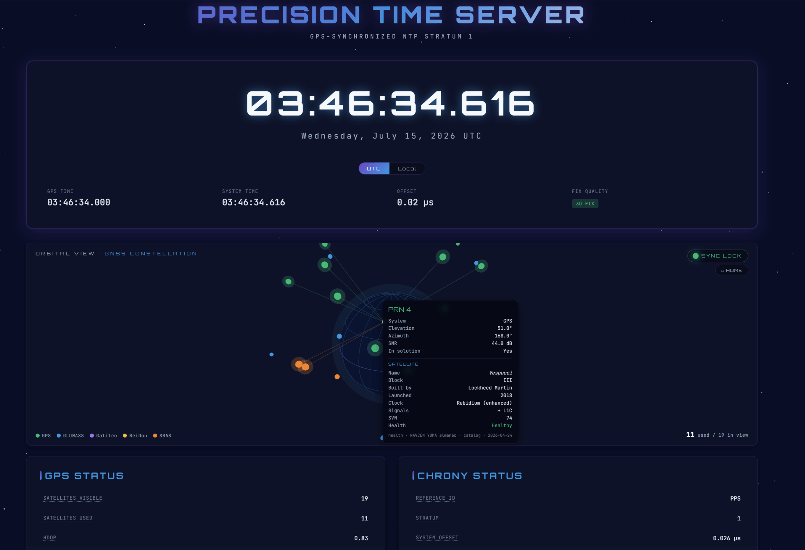
This build stands on the shoulders of the classic jacobdeane.com GPS time server guide, with two deliberate modernizations:

  • chrony instead of ntpd. chrony has native PPS support and a clean socket backend, so you skip the from-source NTP compile entirely.
  • Current Raspberry Pi OS paths. On Bookworm (and Trixie) the boot config lives at /boot/firmware/config.txt, not the old /boot/config.txt (which is now just a placeholder).

How it all fits together

Before wiring anything up, here's a quick overview :

   GPS/RTC HAT (u-blox + PPS)           Raspberry Pi 3 / 4 (host)
 ┌───────────────────────────┐    ┌──────────────────────────────────────────────┐
 │  receiver                 │    │                                              │
 │   • NMEA over UART  ──────┼──▶│  /dev/serial0 ─▶ gpsd ─┐                      │
 │   • PPS on GPIO18   ──────┼──▶│  /dev/pps0 ────────────┼─▶ chrony (stratum 1) │
 └───────────────────────────┘   │                        │        │  serves NTP │
                                 │   gpsd JSON :2947 ─┐    │        ▼   to LAN    │
                                 │   chronyc -c ──────┼────┴─▶ Rust daemon        │
                                 │   (optional) NAVCEN ───▶  :8080 (configurable) │
                                 │                    ├─▶ /data     (SSE telemetry)│
                                 │                    ├─▶ /satinfo  (opt. sat info)│
                                 │                    └─▶ /         (dashboard)   │
                                 └───────────────────────────────┬───────────────┘
                                                                │
                                                   browser ◀────┘  dashboard
  1. The timekeeping path — gpsd reads NMEA + PPS and feeds chrony; chrony disciplines the kernel clock and serves NTP to my network. This is what makes it a stratum-1 server. If you stop reading after Part 6, you've got a fully working time server.
  2. The telemetry path — a small daemon written in Rust that reads the same gpsd data plus chrony's stats and streams them to the dashboard over Server-Sent Events. It's strictly read-only and has zero effect on timekeeping accuracy.

What you'll need

Here's the parts list I used:

PartNotes
Raspberry Pi 3 or 4Both work identically here. The Pi 4 has dedicated Gigabit Ethernet; on the Pi 3, Ethernet shares the USB bus, so keep other USB devices off it. The Pi 5 needs different UART steps and isn't covered.
GPS HAT with PPSI used the Uputronics Raspberry Pi GPS/RTC Expansion Board, and it's what this guide is written against. PPS is mandatory for stratum-1; NMEA alone is only good to a few hundred milliseconds.
GPS antenna (active, timing-grade)Amphenol PCTEL 3978D-HR-DH-W — the exact antenna I used: a weatherproof (IP67) GPS L1 dome antenna with a built-in LNA + filter (~40 dB gain) and a TNC-female connector. A real step up from a puck. Needs a clear-ish view of the sky.
Antenna mounting bracketAmphenol PCTEL MMK1925 — the stainless-steel L-bracket for the WS397x-series dome (fits the 3978D). This and the antenna above are what I actually mounted.
Antenna coaxA run with the right ends for your antenna and HAT (see the note below). I didn't spring for timing-grade coax — I used a cheap SMA extension cable like this one and it's been perfectly fine.

All in all, the project cost ~$240 (inc. shipping, tax, etc). I didn't include the cost of a raspberry pi since I had one unused from a prior project, but assuming you bought a new Pi; you are ~$360.

Notes before we get started

Check your HAT's PPS pin. This guide assumes GPIO18 (the Uputronics default). Some HATs (e.g. Adafruit) use GPIO4. Adjust the gpiopin= value accordingly. Guess wrong and PPS will simply never show up.

Antenna connector & bias (if you're using the dome antenna above). The 3978D outputs TNC female, while most GPS HATs (Uputronics included) use SMA — so plan a coax run with the right ends (TNC-male at the antenna, SMA-male at the HAT) or grab an adapter. It's an active antenna (built-in LNA), so the HAT has to supply DC bias voltage on the coax; the Uputronics HATs do this, but confirm yours does. Being IP67 and bracket-mounted, it's meant to live outdoors on a mast with a clear sky view.

You don't have to mount it outdoors. The 3978D is a weatherproof, IP67, mast-mount dome. It's built to bolt onto a roof and shrug off the weather. I didn't put it on a roof. I bolted it to its MMK1925 bracket, set the whole thing up in my attic under asphalt shingles and 5/8" OSB, and ran it back to the HAT with a cheap SMA extension cable instead of proper timing-grade coax. On paper that's leaving signal on the table three different ways. In practice it's been tracking ~16-20 satellites and holding a sub-microsecond lock the entire time. So: buy the better antenna over fancy cable if you are on a limited budget and don't let "needs a clear view of the sky" scare you into a rooftop install (especially if you are HOA bound and limited to what you can mount outside). An attic on the sky-facing side of the house is likely going to do it for you.

Part 1 — The base OS

Flash Raspberry Pi OS Lite (64-bit) with Raspberry Pi Imager. In the Imager's advanced settings (the gear icon), enable SSH and set the hostname (I'll use timeserver for this guide) and locale before writing. Note: this Pi runs headless, which means you don't have a monitor connected to it, so you want to be able to reach it on first boot.

A word on Bookworm vs Trixie. As of mid-2026 there are active reports of a Trixie serial regression where the GPIO UART stops receiving GPS data on hardware that worked fine on Bookworm (a suspected kernel/PL011 driver issue). For a device whose entire job is reliable time, Bookworm might be the safer choice today; but so far things have worked fine for me. The config paths and overlays are identical — but if NMEA never appears despite correct wiring, jump to the Trixie diagnostic in Troubleshooting. There's also a Debian 12 vs 13 appendix at the bottom.

Boot, SSH to the Pi, and update first:

sudo apt update && sudo apt full-upgrade -y
sudo reboot

Part 2 — Freeing up the hardware UART

Here's the first "gotcha" the Pi throws at you. The Pi 3/4 wire the good UART (PL011) to the onboard Bluetooth by default. We need that UART for the GPS, and we also need to stop Linux from using the serial port as a login console.

2a. Disable the serial login shell (but keep the hardware port)

sudo raspi-config

Under Interface Options → Serial Port:

  • login shell accessible over serial? → No
  • serial port hardware enabled? → Yes

Choose Finish but don't reboot yet, we've got more config to add, and I'd rather reboot once.

2b. Disable Bluetooth to reclaim the UART

sudo vi /boot/firmware/config.txt

New to vi? Here's the reader's digest: press i to start typing (insert mode), make your edits, then hit Esc and type :wq followed by Enter to write and quit. If you fat-finger something and want to bail without saving, Esc then :q! throws your changes away. That's genuinely 90% of what you need to survive vi.

Add this at the end (we'll drop the PPS line in here too in Part 3, so it's a single reboot):

# Reclaim the PL011 UART for GPS by disabling onboard Bluetooth
enable_uart=1
dtoverlay=disable-bt

Older guides use dtoverlay=pi3-disable-bt; the current canonical name is just disable-btraspi-config may have already added an enable_uart=1 line — a duplicate is harmless, but you can keep just one if it bugs you.

Then stop the Bluetooth-UART service:

sudo systemctl disable hciuart

On a Lite image (and commonly on Trixie) this may report Unit hciuart.service does not exist — and that's totally fine. It ships with the pi-bluetooth package, which isn't always installed, and disable-bt already turns Bluetooth off at the device-tree level. The overlay is what actually matters here; this step is just belt-and-suspenders.

Part 3 — Enabling PPS

PPS (pulse-per-second) is the secret sauce. NMEA sentences tell you what second it is; the PPS pulse tells you exactly when that second begins, down to the nanosecond. No PPS, no real stratum-1.

3a. Load the PPS-over-GPIO overlay

Still in /boot/firmware/config.txt, add (adjust gpiopin for your HAT):

# Pulse-Per-Second input on GPIO18
dtoverlay=pps-gpio,gpiopin=18

Then load the kernel module at boot and reboot so both the UART and PPS changes take effect:

echo 'pps-gpio' | sudo tee -a /etc/modules
sudo reboot

3b. Verify raw GPS and PPS

First confirm the UART is on the GPIO header, then read raw NMEA:

ls -l /dev/serial0        # expect: /dev/serial0 -> ttyAMA0
sudo cat /dev/serial0

Always use /dev/serial0 — it's a symlink that always points to whichever UART is on the GPIO header, so you don't have to care whether it's ttyAMA0 or ttyS0 today. Ctrl-C to stop.

If you see garbled characters instead of clean $GNRMC/$GNGGA lines, don't panic, that's a baud-rate mismatch, not a fault. Bytes are flowing; the port's just reading them at the wrong speed. Set the rate explicitly and re-read until it's clean:

sudo stty -F /dev/serial0 9600 raw   && sudo cat /dev/serial0   # common u-blox default
sudo stty -F /dev/serial0 38400 raw  && sudo cat /dev/serial0
sudo stty -F /dev/serial0 115200 raw && sudo cat /dev/serial0   # mine with the Uputronics unit

Write down the rate that produces readable NMEA, you'll need it for gpsd in Part 4. It's a property of your GPS module, not the OS. Many u-blox modules use 9600, but others (including some Uputronics units) run at 115200. Mine was 115200.

Now confirm the pulse itself. This needs a satellite fix; most HATs blink a timepulse LED once they've locked:

sudo apt install -y pps-tools
sudo ppstest /dev/pps0

You want a new assert line every second, timestamped right on the whole second:

source 0 - assert 1699999590.000001416, sequence: 197334 - clear ...
source 0 - assert 1699999591.000000698, sequence: 197335 - clear ...

No output usually just means no fix yet, wait a couple mins or try moving the antenna to a different location. If you are running the antenna in a faraday cage, expect no results since it won't find a satellite.

Part 4 — gpsd

sudo apt install -y gpsd gpsd-clients
sudo vi /etc/default/gpsd

Point it at your HAT (using the baud rate you found in Part 3b):

START_DAEMON="true"
USBAUTO="false"
DEVICES="/dev/serial0 /dev/pps0"
GPSD_OPTIONS="-n -s 115200"

-n polls the GPS immediately at boot; -s 115200 pins the serial speed so gpsd doesn't autobaud its way into garbage. Enable and check:

sudo systemctl enable --now gpsd
sudo systemctl restart gpsd      # ensure it picks up the new config
gpsmon        # or: cgps -s

gpsmon shows the raw feed (fast-scrolling UBX packets are normal and healthy); cgps -s gives a calmer table. You want a 3D fix, satellites with good SNR, low DOP values, and a PPS line with a near-zero offset. That PPS line is the confirmation I was chasing.

Tip: gpsd takes exclusive control of the port. If you want to cat /dev/serial0 again for debugging, stop gpsd first: sudo systemctl stop gpsd gpsd.socket.

Part 5 — chrony with the socket backend

sudo apt install -y chrony

Here's the key design point, and the reason chrony is such an upgrade over the old ntpd dance: gpsd hands the precise PPS timestamp to chrony through a Unix socket (chrony's SOCK refclock). gpsd automatically writes to /run/chrony.<device>.sock once chrony has created it — neatly sidestepping the classic headache where chrony drops privileges and can no longer read /dev/pps0 directly.

sudo vi /etc/chrony/chrony.conf

Add this at the end:

# --- GPS + PPS reference clocks -------------------------------------------

# Coarse absolute time from gpsd (NMEA) via shared memory.
# 'noselect' = never sets the clock, only gives the PPS pulse a whole-second
# label. Tune 'offset' after calibration (Part 7d) if PPS won't lock.
refclock SHM 0 refid GPS precision 1e-1 offset 0.0 delay 0.2 noselect

# Precise PPS via gpsd's socket. gpsd writes here automatically.
# 'lock GPS' anchors each pulse to the GPS second above.
refclock SOCK /run/chrony.pps0.sock refid PPS lock GPS prefer

# Serve time to your LAN (adjust to your subnet) and keep serving during
# brief GPS dropouts.
allow 192.168.0.0/24
local stratum 1

# Optional internet fallback if the antenna fails. Remove for air-gapped use.
pool 2.debian.pool.ntp.org iburst

Restart both, in order — chrony first, so its socket exists by the time gpsd starts:

sudo systemctl restart chrony
sudo systemctl restart gpsd

Confirm the socket exists (it should be owned by root and actually be a socket — note the leading s in the permissions):

ls -l /run/chrony.*.sock      # expect /run/chrony.pps0.sock

Part 6 — Confirming you've actually got a stratum-1 server

Give it 5 minutes to settle, then watch the sources roll in:

watch -n 2 chronyc sources -v

You're looking for #* next to PPS. The asterisk means it's the selected source disciplining the clock. It starts at #? (not enough samples yet), climbs its reachability register (0 → 1 → 3 → 7 → 17 → 37 → 77 → 377), then finally promotes to #*. The internet servers drop to ^- (background sanity checks) once PPS takes over. Watching that register tick up is weirdly satisfying:

MS Name/IP address   Stratum Poll Reach LastRx Last sample
=========================================================================
#? GPS                     0    4  377     14   +42ms[  +42ms] +/- 200ms
#* PPS                     0    4  377     13   -242ns[ -324ns] +/- 1095ns
^- 2.debian.pool.ntp.org   2    6   77     45   -437us[ -436us] +/-  13ms

Then confirm the server itself:

chronyc tracking

Look for Stratum : 1Reference ID … (PPS), and a System time offset down in the sub-microsecond range. That, right there, is a working stratum-1 time server. I may have taken a screenshot.

Reading the numbers: System time / Last offset are your current accuracy (nanoseconds-to-microseconds once locked). RMS offset looks alarming at first (hundreds of µs) because it's a rolling average still dominated by the noisy warm-up; it falls steadily the longer it runs, so don't judge it too early. Root delay near zero and Reference ID = PPS confirm a direct hardware lock.

The falseticker trap. chrony will reject PPS if the GPS (NMEA) label is more than ±200 ms off the true second. If PPS stays stuck at #?, that's almost always the culprit, calibrate the offset (Part 7d).

At this point the time server itself is done. Below is the fun part of visualizing the setup. If you just wanted accurate time, congratulations, you can stop here.

Part 7 — The telemetry daemon

Now to create a live dashboard to visualize everything. The daemon does four things:

  1. Connects to gpsd's JSON socket on 127.0.0.1:2947 — the same protocol libgps speaks, so I get identical data without any C FFI.
  2. Polls chrony once a second with chronyc -c tracking (the -c flag hands back machine-readable CSV from chrony's command socket).
  3. Merges both, streams them to the browser over SSE at /data, and serves the dashboard.
  4. (Optional, off by default) fetches and caches the NAVCEN GPS almanac and serves it at /satinfo for satellite-health enrichment (more in Part 8).

Get the code, the daemon and dashboard live on GitHub: JackStromberg/gps-timeserver-daemon. Clone it directly onto the Pi:

sudo apt install -y git
git clone https://github.com/JackStromberg/gps-timeserver-daemon.git
cd gps-timeserver-daemon
ls -al

You should end up with:

gps-timeserver-daemon/
├── Cargo.toml
├── src/main.rs
└── static/index.html      # already set to live mode (USE_SIMULATION = false)

7a. Install Rust and build

curl --proto '=https' --tlsv1.2 -sSf https://sh.rustup.rs | sh   # press Enter for defaults
source "$HOME/.cargo/env"
cargo --version                                                  # should print a version
sudo apt install -y build-essential                              # C linker (Lite images lack it)
cd gps-timeserver-daemon
cargo build --release

cargo: command not found right after installing? The installer can't modify an already-running shell's PATH. Run source "$HOME/.cargo/env" (or just open a new terminal). If ls ~/.cargo/bin/cargo doesn't exist, the install didn't finish — re-run the curl … | sh line.

error: linker 'cc' not found? Install build-essential (above) and rebuild.

Fair warning: the first build on a Pi is slow. It compiles tokio, axum, reqwest, and the whole rustls TLS stack from scratch (several minutes), and it may look completely frozen at the final link step. That's normal. Subsequent builds are incremental and quick.

7b. Run it

./target/release/gps-timeserver-daemon

It prints its listen address and stays running (it's serving, so it won't hand you back a prompt). Open http://<pi-ip>:8080 from a browser on your LAN and you should see the dashboard light up.

The port is configurable — see Part 8. If 8080 is already taken (a Docker service, say), you'll get AddrInUse; set a different PORT rather than editing code.

7c. The /data contract

The daemon emits one JSON object per second in this shape (the dashboard reads exactly these field names):

{
  "timestamp": "2026-07-07T12:34:56Z",
  "time":   { "gps_time": "...", "system_time": "...", "offset_us": 0.42,
              "time_since_last_fix": 0.3, "leap_seconds": 18 },
  "gps":    { "mode": 3, "satellites_visible": 12, "satellites_used": 9,
              "hdop": 0.8, "vdop": 1.1, "pdop": 1.3, "gdop": 1.5, "tdop": 0.7,
              "ept": 0.005, "latitude": 51.5, "longitude": -0.12, "altitude": 35.2,
              "epx": 3.1, "epy": 4.2, "epv": 6.0, "track": 0.0, "speed": 0.0,
              "climb": 0.0, "eps": 0.5 },
  "chrony": { "reference_id": "PPS", "stratum": 1, "system_time": 0.0000004,
              "last_offset": 0.0000004, "rms_offset": 0.0000012,
              "frequency_ppm": -2.3, "residual_freq_ppm": 0.001, "skew_ppm": 0.02,
              "root_delay": 0.00001, "root_dispersion": 0.00002,
              "update_interval": 16.0, "leap_status": "Normal" },
  "device": { "path": "/dev/serial0", "driver": "u-blox", "subtype": "...",
              "bps": 115200, "parity": "N", "native": true, "cycle": 1.0, "mincycle": 1.0 },
  "version":{ "release": "3.25", "proto_major": 3, "proto_minor": 15 },
  "satellites": [
    { "prn": 5, "system": "GPS", "elevation": 70, "azimuth": 251, "snr": 42, "used": true }
  ]
}

Telemetry::to_json() in src/main.rs is the single source of truth for this contract — if you want to add a field, that's the one place to touch.

7d. Calibrating the GPS offset (optional)

If PPS refuses to lock, let it run ~15 minutes, then read the measured GPS offset:

chronyc sourcestats

Take the GPS source's Offset (say +512ms), convert to seconds, and set it as offset on the SHM 0 line in chrony.conf (e.g. offset 0.512). Restart chrony. This nudges the NMEA label back inside the ±200 ms window so PPS gets accepted — the fix for that falseticker trap I mentioned above.

Part 8 — Configuration via environment variables

I wanted to be able to change behavior without recompiling, so the daemon reads a handful of environment variables at startup. Set them when running manually, or via Environment= lines in the systemd unit (Part 9).

VariableDefaultPurpose
PORT8080Port to bind (binds 0.0.0.0:PORT).
LISTEN_ADDR(unset)Full host:port; overrides PORT. Use 127.0.0.1:8088 to serve only locally, 0.0.0.0:8088 for the LAN.
SATINFO_ENABLED(off)1/true/yes/on enables the optional NAVCEN satellite-info fetcher. Off means the daemon makes zero outbound network calls — safe for air-gapped setups.
SATINFO_INTERVAL_HOURS168 (weekly)How often to refresh the NAVCEN data. The constellation changes only a few times a year, so weekly (or 720 ≈ monthly) is plenty.
SATINFO_URLNAVCEN YUMA almanacOverride the source if needed.

The optional satellite-info fetcher

When SATINFO_ENABLED=1, a background task fetches the NAVCEN GPS almanac (US Coast Guard, public-domain US-government data), caches it in memory, and serves it at /satinfo. The dashboard uses it to add live health status to each GPS satellite's hover tooltip. On failure it retries in an hour; on success it waits the full interval. Left disabled (the default), /satinfo returns {"enabled": false} and the dashboard silently falls back to its built-in reference table — so nothing breaks either way.

Quick checks once you've enabled it:

journalctl -u timeserver-dashboard -n 20 --no-pager   # look for: satinfo: fetched N satellites
curl -s localhost:8080/satinfo | head -c 300          # expect "enabled":true and a satellites object

On data sources & licensing (not legal advice): NAVCEN is public-domain US-government data — no account, redistribution-safe. The dashboard's built-in reference table is assembled from public GPS records. If you instead point live mode at CelesTrak, respect their access etiquette (cache; don't poll more than roughly every 2 hours) and cite them. There's a fuller Licensing appendix at the bottom.

Part 9 — Running it at boot

I want this thing to just come back on its own after a power blip, so let's give it a systemd unit:

sudo vi /etc/systemd/system/timeserver-dashboard.service
[Unit]
Description=GPS Timeserver Dashboard
After=network-online.target gpsd.service chrony.service
Wants=network-online.target

[Service]
# Adjust User and paths to where you put the project.
User=pi
WorkingDirectory=/home/pi/gps-timeserver-daemon
ExecStart=/home/pi/gps-timeserver-daemon/target/release/gps-timeserver-daemon
Restart=on-failure
RestartSec=3

# Optional configuration (see Part 8):
Environment=PORT=8088
# Environment=SATINFO_ENABLED=1
# Environment=SATINFO_INTERVAL_HOURS=168

[Install]
WantedBy=multi-user.target

WorkingDirectory matters more than it looks. The daemon serves static/index.html relative to where it runs, and systemd does not inherit your shell's current directory. Point this at the wrong place and you'll get a 404 for the dashboard.

Enable and verify:

sudo systemctl daemon-reload
sudo systemctl enable --now timeserver-dashboard
systemctl status timeserver-dashboard          # expect: active (running)
journalctl -u timeserver-dashboard -n 5 --no-pager   # confirm the listen address

Whenever you edit the unit file (say, to change an Environment= line), run sudo systemctl daemon-reload and then sudo systemctl restart timeserver-dashboard. Skipping the reload is the classic "my change didn't take" gotcha. systemctl show timeserver-dashboard -p Environment prints what systemd is actually passing, which is handy when you're sure you fixed it but it disagrees.

One nice quality-of-life note: editing only static/index.html (HTML/CSS/JS) needs no rebuild and no restart — the daemon serves it from disk at request time. Just hard-refresh the browser (Ctrl-Shift-R). Only changes to src/main.rs or Cargo.toml require cargo build --release.

Part 10 — Serving time to the rest of the network

Everything so far only disciplines the Pi's own clock. To let other machines sync from it, chrony has to answer NTP requests — and it refuses by default, which is a good safety default but not what we want here.

10a. Match the allow line to your LAN

hostname -I               # your Pi's IP, e.g. 192.168.1.50

If the Pi is 192.168.1.50, your subnet is likely 192.168.1.0/24. Edit chrony.conf so the allow line matches — a whole subnet (allow 192.168.1.0/24), a single host (allow 192.168.1.100), or allow all only if you deliberately mean to serve the public — then restart:

sudo systemctl restart chrony

10b. Confirm it's serving

sudo ss -ulnp 'sport = :123'    # something should be bound to UDP 123
chronyc clients                 # machines that have requested time (empty until clients connect)

If you run a firewall on the same Raspberry Pi (ufwnftables, or Docker-managed iptables), open NTP: sudo ufw allow 123/udp. A plain Lite install has no firewall and needs nothing.

10c. Point your clients at the Pi

Your Pi is stratum 1, so anything syncing to it becomes stratum 2 — perfect for a LAN. Here's how I pointed a few common clients at it:

  • Router: set its NTP server to the Pi's IP — this pushes time locally to every device automatically, using it as an ntp source.
  • Linux: add server <pi-ip> iburst to /etc/chrony/chrony.conf, restart chrony.
  • Windows: w32tm /config /manualpeerlist:"<pi-ip>" /syncfromflags:manual /update then w32tm /resync.
  • macOS: System Settings → General → Date & Time, or sudo sntp -sS <pi-ip>.

Verify from a client with chronyc -h <pi-ip> trackingsntp <pi-ip>, or ntpdate -q <pi-ip>. Back on the Pi, chronyc clients will list everyone pulling time from you.

Part 11 — Actually using the dashboard

Open http://<pi-ip>:<port> (default 8080, or 8088 in my examples above). Everything updates once per second from the live feed.

Time header. A large clock with millisecond precision, plus GPS time, system time, and the chrony offset. The UTC / Local toggle under the clock switches every time on the page between UTC and your browser's local zone, and it remembers your choice across reloads.

Orbital globe (the hero panel, and my favorite). A holographic Earth with each GNSS satellite placed in true 3D from its azimuth/elevation, color-coded by constellation, with beams running from the satellites in use down to a marker at your location.

  • Drag to rotate (mouse or touch): horizontal spins around the poles, vertical tilts.
  • Home button (top-right) or double-click the globe to glide back to the default view.
  • Hover a satellite for its details: PRN, constellation, elevation, azimuth, SNR, and whether it's in the solution — plus, for GPS, catalog facts (block, manufacturer, clock type, launch year, name, SVN) and, if /satinfo is enabled, live health.
  • Hover a legend entry (GPS/GLONASS/Galileo/BeiDou/SBAS) for a one-line explanation of that constellation.

Status panels. GPS Status, Chrony Status, Position & Navigation, and System Info. Hover any metric label (they've got a dotted underline) for an explanation of what it means and what a good value looks like — HDOP, TDOP, EPX/EPY/EPV, the chrony offsets, and so on. I added these mostly so I'd stop having to look them up myself.

Sky view + satellite table. Polar az/el plot, plus a detailed per-satellite table.

Satellite-info modes (dashboard side)

Near the top of the <script> in static/index.html:

  • SATINFO_MODE — 'daemon' (default; asks this server's /satinfo, no CORS, falls back to the built-in table if the server has fetching disabled), 'offline' (built-in table only, never fetches), 'celestrak' (fetch CelesTrak directly from the browser; may hit CORS), or 'off'.
  • The built-in table always supplies block/manufacturer/clock/name/launch; /satinfo adds live health on top.

Previewing with simulated data

static/index.html ships with const USE_SIMULATION = false; (live). To preview the UI without any hardware — say you're building this on your laptop before the HAT arrives — open a copy with it set to true. It generates fake data (a fixed location, invented satellites, a locked stratum-1 state) so every visual works offline.

Heads up: the globe and all hover tooltips are mouse-based, so the hover interactions won't appear on touchscreens (dragging the globe still works via touch).

Part 12 — Optional: running the dashboard in Docker

You can containerize the dashboard daemon — but keep gpsd + chrony on the host. The kernel clock is a single host-wide resource; putting chrony in a container means granting it SYS_TIME and steering the host clock across the container boundary — extra layers wrapped around your most timing-sensitive component. The daemon, on the other hand, is a read-only consumer and containerizes cleanly with zero precision impact.

Here's an example multi-stage Dockerfile:

# Build
FROM rust:1-bookworm AS build
WORKDIR /app
COPY Cargo.toml Cargo.lock* ./
COPY src ./src
RUN cargo build --release

# Runtime
FROM debian:bookworm-slim
RUN apt-get update && apt-get install -y --no-install-recommends \
      chrony ca-certificates && rm -rf /var/lib/apt/lists/*
WORKDIR /app
COPY --from=build /app/target/release/gps-timeserver-daemon /usr/local/bin/
COPY static ./static
CMD ["gps-timeserver-daemon"]

Note that chrony is installed here only for its chronyc client (the daemon shells out to it) — the container does not run a chrony daemon. Run it sharing the host network and chrony's command socket:

docker build -t timeserver-dashboard .

docker run -d --name timeserver-dashboard \
  --network host \
  -e PORT=8088 \
  -e SATINFO_ENABLED=1 \
  -v /run/chrony:/run/chrony:ro \
  --restart unless-stopped \
  timeserver-dashboard
  • --network host lets the daemon reach host gpsd at 127.0.0.1:2947 and keeps PORT/LISTEN_ADDR working normally.
  • Mounting /run/chrony gives the container's chronyc access to chrony's command socket.
  • You do not need --device=/dev/serial0 or /dev/pps0 here — the daemon never touches the hardware directly; it reads gpsd and chronyc. (Those devices only matter if you were containerizing gpsd/chrony too, which, again, I'd steer you away from.)

Troubleshooting

Here's a running list of things I've stumbled across:

SymptomLikely cause / fix
cat /dev/serial0 shows nothingUART not freed. Confirm dtoverlay=disable-bt is in /boot/firmware/config.txt (not /boot/), hciuart disabled, rebooted. Check ls -l /dev/serial0 points to ttyAMA0.
cat /dev/serial0 shows garbled textBaud-rate mismatch (not a fault). Set the rate with stty -F /dev/serial0 <rate> raw and re-read; use the working rate in gpsd's -s.
Silent serial on Trixie only, same HW worked on BookwormSuspected Trixie UART/PL011 regression. Diagnose: pinctrl poll 14-15 &, then trigger GPS data — if GPIO15 (RX) never changes level, no bytes are reaching the pin (a kernel issue, not your config). Try linux-modules-extra-raspi, pin an older kernel, or fall back to Bookworm.
ppstest prints nothingNo fix yet, or wrong PPS pin. Give it sky view; verify gpiopin= (4 vs 18).
chrony PPS stuck at #?GPS/NMEA offset > 200 ms → falseticker. Calibrate the SHM 0 offset (Part 7d); make sure /dev/pps0 is in gpsd DEVICES and /run/chrony.pps0.sock exists.
Dashboard "Waiting for data..."Daemon can't reach gpsd. Check systemctl status timeserver-dashboard and that gpsd is up on :2947.
Dashboard returns 404WorkingDirectory in the unit doesn't point at the project root, so static/index.html isn't found. Fix the path, daemon-reload, restart.
Daemon exits with AddrInUseThe port's taken (e.g. Docker on 8080). Set Environment=PORT=8088 (or another free port); sudo ss -ltnp 'sport = :8080' shows the culprit.
/satinfo shows enabled:falseSATINFO_ENABLED not set/true, or daemon-reload skipped after editing the unit. systemctl show … -p Environment to verify.
/satinfo enabled:true but count:0NAVCEN fetch/parse failed (check the error field and the journal). Network blip → it retries within an hour; persistent → check outbound HTTPS.
cargo: command not foundPATH not loaded: source "$HOME/.cargo/env". If ~/.cargo/bin/cargo is missing, re-run the rustup installer.
cargo build → linker 'cc' not foundsudo apt install -y build-essential, then rebuild.
Clients can't syncThe allow subnet in chrony.conf has to match your LAN; open UDP/123 if you run a firewall.
Satellites look frozen on the globeExpected! GPS is MEO (~2 orbits/day) and moves only gradually in az/el; the receiver also updates angles slowly. Check back in 20–30 min and the pattern will have shifted.

What you end up with

So where does all this leave you? Two things:

  • stratum-1 NTP server disciplined by GPS + PPS, accurate to the microsecond or better, serving your whole LAN with no internet dependency. Every device on my network now sets its clock from a little box in my attic pulling time straight out of the sky, and I find that quietly delightful.
  • live dashboard showing the calculated time, full gpsd + chrony stats with hover explanations, an interactive 3D constellation globe with per-satellite detail, and a sky view — all fed by the same hardware over SSE, with a clean JSON contract you can extend however you like.

If you want to keep tinkering, there are really just two files worth revisiting: src/main.rs (where Telemetry::to_json() defines the data contract) and static/index.html (METRIC_HELPGPS_SAT_DB, and the render functions). Everything I'd want to customize lives in one of those two places.

If you made it this far, congrats on your new clock! Your clock is now more accurate than it has any reason to be!


Appendix A — Debian 12 (Bookworm) vs Debian 13 (Trixie)

Both work; most steps are identical. I verified everything on Debian 12 & 13 exactly as written above.

TopicDebian 12 / BookwormDebian 13 / Trixie
Boot config path/boot/firmware/config.txtSame
disable-bt / pps-gpio overlaysSameSame
Serial device/dev/serial0 → ttyAMA0 (always prefer serial0)Same
systemctl disable hciuartUsually succeedsOften Unit … does not exist — harmless
GPIO UART receiving GPSReliableRegression risk (mid-2026): no RX bytes despite correct config. Diagnose with pinctrl poll 14-15; may need linux-modules-extra-raspi, an older kernel, or Bookworm
gpsd / chronyStock; config as writtenNewer; same config syntaxchronyc -c tracking CSV unchanged
RecommendationPreferred for a time serverWorks, but verify the serial link early

Remember: serial baud rate is a property of your GPS module, not the OS — it's handled identically on both.

Appendix B — Environment variables (quick reference)

Daemon (systemd Environment= or shell):

VariableDefaultNotes
PORT8080Bind port.
LISTEN_ADDR(unset)Full host:port; overrides PORT.
SATINFO_ENABLEDoff1/true/yes/on to enable NAVCEN fetch. Off = no outbound calls.
SATINFO_INTERVAL_HOURS168Refresh cadence (weekly).
SATINFO_URLNAVCEN YUMASource override.

Dashboard (static/index.html constants):

ConstantDefaultNotes
USE_SIMULATIONfalsetrue = fake data for previewing.
SATINFO_MODE'daemon'daemon / offline / celestrak / off.

Appendix C — Licensing & data sources

Not legal advice. For personal, non-commercial use you're clear on all of the below.

  • GPS orbital/almanac data is US-government, public-domain. NAVCEN (US Coast Guard) serves it with no account and is redistribution-safe — the recommended live source here.
  • CelesTrak (an alternative live source) redistributes the same government data and adds convenient PRN/block labeling. Respect their access etiquette: cache results and don't poll more than roughly once every two hours; cite CelesTrak; note that it isn't an official source. Commercial redistribution is a "contact them first" situation.
  • The dashboard's built-in reference table is factual data (which PRN, block, launch year, manufacturer) assembled from public records; facts aren't copyrightable.
  • For anything commercial or internet-facing at scale using, review each source's current terms directly.
Headless Raspberry Pi Image based on Debian Trixie (Like Raspbian Lite)

I'm in the process on repurposing a few Raspberry Pis and noticed Debian 13 has officially been released (at time of writing), but Raspberry Pi OS is still on Debian 12.

If you're looking to create a custom Raspberry Pi OS image tailored for headless deployment, this guide walks you through using the official pi-gen tool to build your own image — based on Debian Trixie (Debian 13).

While I've tried to write this document in the context of a how-to, it's more of a reflection on what I did vs something formal.

⚠️ Disclaimer: Since this image is not built or maintained by the Raspberry Pi Foundation, you may encounter compatibility issues, hardware quirks, or missing Raspberry Pi-specific features. Official support for this setup is limited, and it's best suited for experimentation or advanced use cases. I don't work for the Raspberry Pi project, so follow at your own risk.

That all being said, here's what following this page would yield:

  • Uses the same tool the Raspberry Pi Foundation uses to generate official images
  • Builds a minimal system similar to Raspberry Pi OS Lite
  • Builds an Arm64 image (not 32-bit)
  • Has SSH enabled
  • Supports customization of locale, timezone, and user credentials

✅ Why Build Your Own Image?

You may want a custom image when:

  • You need headless deployment out of the box (no keyboard/mouse/monitor)
  • You want SSH access enabled by default
  • You want to preconfigure locales or packages for embedded or production use

🔧 Prerequisites

To follow this guide, it assumes usage of a few linux utilities / command. It assumes you are using and have available:

  • A macOS (Apple Silicon) or Linux machine
  • git, docker, and optionally qemu-user-static (only needed for x86)
  • ~10–20GB of free disk space

🧰 Step 1: Clone pi-gen

git clone --branch arm64 https://github.com/RPi-Distro/pi-gen.git
cd pi-gen

From the docs at time of this article:

Note: 32 bit images should be built from the master branch. 64 bit images should be built from the arm64 branch.

Tip: They have different branches based on debian OS version you want to target.


🧾 Step 2: Create the config File

You can define a file to customize that tells the image how to be customized out of box. Since we are a headless setup, we don't want to have to connect a monitor, keyboard, mouse, etc; so this file will define how the operating system should be customized on first startup.

Inside the pi-gen directory, create a file named config:

touch config

Then edit it with your preferred editor (nano, vim, VSCode, etc.):

Example config File

# Debian release to build (note, you should target the applicable branch when changing releases)
RELEASE=trixie

# Name of the image
IMG_NAME="raspios-trixie-arm64"

# Build 64-bit image
ARCH=arm64

# Enable SSH by default
ENABLE_SSH=1

# Set default username and password
FIRST_USER_NAME="pi"
FIRST_USER_PASS="raspberry"

# Don't compress the image – output raw .img file
DEPLOY_COMPRESSION=none

# Set timezone to UTC+0
TIMEZONE_DEFAULT="Etc/UTC"

# Don't use QEMU (set to 1 if not on Arm based architecture)
USE_QEMU=0


🌍 Locales, Keyboard, and Timezone

To change the system locale or timezone, you can add these optional variables:

# Locale
LOCALE_DEFAULT="en_US.UTF-8"

# Keyboard layout
KEYBOARD_KEYMAP="us"
KEYBOARD_LAYOUT="English (US)"

# Timezone (examples)
TIMEZONE_DEFAULT="Etc/UTC"       # UTC+0
TIMEZONE_DEFAULT="America/New_York"
TIMEZONE_DEFAULT="Europe/London"
TIMEZONE_DEFAULT="Asia/Tokyo"

You can find all available timezones on a Linux system via:

ls /usr/share/zoneinfo

🏗️ Step 3: Build the Image

If you don't want the desktop environment (headless setup), create the following skip files to eliminate creation of the full desktop images:

touch ./stage3/SKIP ./stage4/SKIP ./stage5/SKIP
touch ./stage4/SKIP_IMAGES ./stage5/SKIP_IMAGES

To start the build, run the following:

./build-docker.sh

This will:

  • Pull the necessary Docker images
  • Run through the build stages (stage0 to stage2 (assuming you created the skips))
  • Output a raw .img file(s) in the deploy/ folder

Example output without skip

copying log from container pigen_work to deploy/
total 35235816
drwxr-xr-x  10 jack  staff   320B Sep  6 11:58 .
drwxr-xr-x  23 jack  staff   736B Sep  6 11:57 ..
-rw-r--r--   1 jack  staff   8.3G Sep  6 11:57 2025-09-06-raspios-trixie-arm64-full.img
-rw-r--r--   1 jack  staff   245K Sep  6 11:57 2025-09-06-raspios-trixie-arm64-full.info
-rw-r--r--   1 jack  staff   2.6G Sep  6 11:56 2025-09-06-raspios-trixie-arm64-lite.img
-rw-r--r--   1 jack  staff    76K Sep  6 11:56 2025-09-06-raspios-trixie-arm64-lite.info
-rw-r--r--   1 jack  staff   5.8G Sep  6 11:56 2025-09-06-raspios-trixie-arm64.img
-rw-r--r--   1 jack  staff   213K Sep  6 11:56 2025-09-06-raspios-trixie-arm64.info
-rw-r--r--   1 jack  staff   1.0M Sep  6 11:58 build-docker.log
-rw-r--r--   1 jack  staff    10K Sep  6 11:57 build.log

Example output with the skip files

copying results from deploy/
copying log from container pigen_work to deploy/
total 5525296
drwxr-xr-x   6 jack  staff   192B Sep  6 12:03 .
drwxr-xr-x  23 jack  staff   736B Sep  6 12:03 ..
-rw-r--r--   1 jack  staff   2.6G Sep  6 12:03 2025-09-06-raspios-trixie-arm64-lite.img
-rw-r--r--   1 jack  staff    76K Sep  6 12:03 2025-09-06-raspios-trixie-arm64-lite.info
-rw-r--r--   1 jack  staff   308K Sep  6 12:03 build-docker.log
-rw-r--r--   1 jack  staff   5.8K Sep  6 12:03 build.log

💾 Step 4: Flash the Image to SD Card

After the build completes, write the image to an SD card. You can do this via command line or via the official Raspberry Pi Imager.

WARNING: make absolutely sure if you use the commands below you do not target the wrong disk. These commands can result in data loss. You do not hold me liable for data loss if using this approach!

On macOS or Linux:

  1. Identify the SD card:
diskutil list       # macOS
lsblk               # Linux
  1. Unmount the disk (macOS):
diskutil unmountDisk /dev/disk2
  1. Write the image:
sudo dd if=deploy/2025-09-06-raspios-trixie-arm64-lite.img of=/dev/rdisk5 bs=4m conv=fsync

⚠️ Replace /dev/rdisk5 with the correct device for your SD card.


🔌 Step 5: Boot the Pi

  • Insert the SD card into your Pi
  • Connect an Ethernet cable
  • Power on the Pi

You should:

  • See the Pi boot
  • Get a login prompt (no GUI)
  • Be able to SSH in using the IP address assigned via DHCP

🧩 Optional: Add SSH Key or Preseed Files

You can also preconfigure:

  • Your SSH public key
  • A custom hostname
  • Static IP
  • Additional packages

Let me know if you want a follow-up post for those.


✅ Recap

FeatureConfigured?
Debian Version✅ Trixie (Debian 13)
SSH Enabled✅ Yes
GUI/Desktop❌ No
Output Format✅ Raw .img
Build Host✅ Apple Silicon (no QEMU)
Locale / Timezone✅ UTC (editable)

🧭 Conclusion

By using pi-gen, you're following the official image-building process used by the Raspberry Pi Foundation — but with full control over your system. This process can also be used for embedded projects, production environments, or anyone who needs a tightly configured headless system.

Using SDRplay RSPduo with RTLSDR-Airplay and a RaspberryPi

One of the side projects I have is rebroadcasting local ATC (Air Traffic Control) audio from my local airport to LiveATC.net. I previously had an RTL-SDR dongle connected to a RaspberryPi 1 Model B, which then rebroadcasted to LiveATC via IceCast. While I've had success the past few years broadcasting, overhead plans were really the only thing that was clear; being distant from the airport, receiving broadcasts from the tower were a slim to none at best.

In doing a bit of research I settled on purchasing a SDRplay RSPduo and Raspberry Pi 4, which seems to help with noise. Pairing the SDRplay with the newest version of RTLSDR-Airplay, I was able to achieve much clearer audio/hear things I couldn't before. While I'm using the SDRplay RSPduo, this guide can be used for their other devices such as the Rsp1a and RSPdx as well (likely others as this guide ages). Here's a reflection on how I got things setup.

Update Raspbian packages

First, update your Linux packages to latest version. I'm running the latest version of Raspbian / Debian.

sudo apt-get update && sudo apt-get upgrade

Disable WiFi/Bluetooth

This is optional, but I figured I'd disable the radios on the RaspberryPi to further mitigate as much possible noise as possible. First, you can disable both radios by editing /boot/config.txt via the vi text editor (this can actually be configured by placing this file on your SD-Card you attach to your Raspberry Pi during first-time boot). Official details on the boot overlays can be found here.

sudo vi /boot/config.txt

Once in vi, press i to insert the following lines:

dtoverlay=disable-bt
dtoverlay=disable-wifi

Press the escape key and then type :wq to write the changes to the file and exit vi.

Lastly, execute the following command to disable the UART bluetooth service.

sudo systemctl disable hciuart

Download & Install RSP Control Library + Driver

First, you will want to grab the latest SDRplay Drivers and Libraries. You can do this by navigating to SDRplay's website and selecting RSPduo and ARM Raspberry Pi OS for the download. Then click the API button. Now this is kinda difficult if you are SSHed into the Pi, so I'd find the latest version from their website and then use the following commands below to remotely download the software (substituting in the version number to grab the latest download) and install it and reboot after install (rebooting after installation is strongly recommended).

Execute the following commands:

# Navigate to home directory
cd ~
# Download latest API Library + Driver
wget https://www.sdrplay.com/software/SDRplay_RSP_API-Linux-3.15.2.run
# Provide execution rights to install the software
chmod a+x SDRplay_RSP_API-Linux-3.15.2.run
# Run the installer
sudo ./SDRplay_RSP_API-Linux-3.15.2.run
# Reboot the machine
sudo reboot now

Build and install SoapySDR from source

In this section, we need to install SoapySDR which is a vendor and platform neutral SDR support library. Essentially this means that instead of needing a bunch of developers to write integrations into all the different SDRs, other software can leverage these interfaces to skip worrying about device compatibility and focus on what the application needs to do. As we'll see later, RTLSDR-Airband does exactly this to provide support for tons of different SDRs. Kudos to the PothosWare team for enabling developers all over the world to build all sorts of SDR projects!

So, to get this installed, we need to clone the source code from their GitHub repo and compile the project. Official documentation on this process can be found on their wiki, but I'm going to try and simplify everything here.

Since Raspberry Pi doesn't come with Git, I am going to use wget and unzip to do this, but if you don't mind installing Git, that'd be the easier way to "clone" down the latest source code from GitHub (make sure you replace versions where appropriate, at time of writing this, 0.8.1 is the latest version).

# Install dependencies needed to build this project
sudo apt-get install cmake g++ libpython-dev python-numpy swig
# Make sure we are back in our home directory
cd ~
# Grab latest tarball from GitHub
wget -O soapy-sdr-0.8.1.tar.gz https://github.com/pothosware/SoapySDR/archive/soapy-sdr-0.8.1.tar.gz
# Extract the tarball (this is like unzipping a .zip on Windows)
tar xvfz soapy-sdr-0.8.1.tar.gz

# Change directories into the new SoapSDR folder
cd SoapySDR-soapy-sdr-0.8.1

# Make a new folder called build
mkdir build

# Change directories into the build folder
cd build

# Execute cmake build automation
cmake ..

# Make installer (-j4 parameter increases build threads to make compilation quicker)
make -j4
# Make the installer copy files to right locations
sudo make install
sudo ldconfig #needed on debian systems
# Navigate back to home directory
cd ~
# Delete the SoapySDR folder since we are done with it
sudo rm -R SoapySDR-soapy-sdr-0.8.1

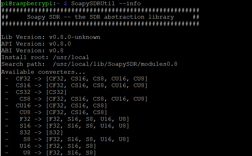
At this point, you should be able to execute the SoapySDRUtil command and see the version you installed.

SoapySDRUtil --info

You should get something like this (note: you will likely see a missing module; that's ok for right now!):

Build and install SoapySDR Play module from source

Now that we have SoapySDR installed, we need to install the module to allow it to control the SDRplay device. Similiar to SoapySDR install, we'll pull down the latest files from the SoapySDR Play Module GitHub repo, build the installer, execute it, and verify that all went well. Official instructions can be found on their wiki as well.

# Make sure we are back in our home directory
cd ~
# Grab latest tarball from GitHub
wget -O SoapySDRPlay.zip https://github.com/pothosware/SoapySDRPlay3/archive/refs/heads/master.zip
# Unzip the archive
unzip SoapySDRPlay.zip
# Change directories into the new SoapSDR folder
cd SoapySDRPlay3-master
# Make a new folder called build
mkdir build
# Change directories into the build folder
cd build
# Execute cmake build automation
cmake ..
# Make installer
make
# Make the installer copy files to right locations
sudo make install
sudo ldconfig #needed on debian systems
# Navigate back to home directory
cd ~
# Delete the SoapySDR folder since we are done with it
rm -R SoapySDRPlay3-master

Plug in SDRplay RSPduo device and verify we see it

If you haven't already, go ahead and plug in your SDRplay RSPduo. Next, let's verify we see it using the SopaySDRUtil command.

SoapySDRUtil --probe="driver=sdrplay"

You should see something like this and you should see your device and hardware version (note the hardware hardware= value as you may need that later). In addition, one thing that is neat about the RSPduo is there are multiple tuners/antennas. You will be able to see these values in the probe output. Once you enable RTLSDR-Airplay, you'll notice active antennas are removed from the list of available devices.


pi@raspberrypi:~ $ SoapySDRUtil --probe="driver=sdrplay"
######################################################
##     Soapy SDR -- the SDR abstraction library     ##
######################################################

Probe device driver=sdrplay
[INFO] devIdx: 0
[INFO] hwVer: 3
[INFO] rspDuoMode: 1
[INFO] tuner: 1
[INFO] rspDuoSampleFreq: 0.000000

----------------------------------------------------
-- Device identification
----------------------------------------------------
  driver=SDRplay
  hardware=RSPduo
  sdrplay_api_api_version=3.070000
  sdrplay_api_hw_version=3

----------------------------------------------------
-- Peripheral summary
----------------------------------------------------
  Channels: 1 Rx, 0 Tx
  Timestamps: NO
  Other Settings:
     * RF Gain Select - RF Gain Select
       [key=rfgain_sel, default=4, type=string, options=(0, 1, 2, 3, 4, 5, 6, 7, 8, 9)]
     * IQ Correction - IQ Correction Control
       [key=iqcorr_ctrl, default=true, type=bool]
     * AGC Setpoint - AGC Setpoint (dBfs)
       [key=agc_setpoint, default=-30, type=int, range=[-60, 0]]
     * ExtRef Enable - External Reference Control
       [key=extref_ctrl, default=true, type=bool]
     * BiasT Enable - BiasT Control
       [key=biasT_ctrl, default=true, type=bool]
     * RfNotch Enable - RF Notch Filter Control
       [key=rfnotch_ctrl, default=true, type=bool]
     * DabNotch Enable - DAB Notch Filter Control
       [key=dabnotch_ctrl, default=true, type=bool]

----------------------------------------------------
-- RX Channel 0
----------------------------------------------------
  Full-duplex: NO
  Supports AGC: YES
  Stream formats: CS16, CF32
  Native format: CS16 [full-scale=32767]
  Antennas: Tuner 1 50 ohm, Tuner 1 Hi-Z, Tuner 2 50 ohm
  Corrections: DC removal
  Full gain range: [0, 48] dB
    IFGR gain range: [20, 59] dB
    RFGR gain range: [0, 9] dB
  Full freq range: [0.001, 2000] MHz
    RF freq range: [0.001, 2000] MHz
    CORR freq range:  MHz
  Sample rates: 0.0625, 0.096, 0.125, 0.192, 0.25, ..., 6, 7, 8, 9, 10 MSps
  Filter bandwidths: 0.2, 0.3, 0.6, 1.536, 5, 6, 7, 8 MHz

Build and install RTLSDR-Airband from source

RTLSDR-Airband is an open source project that allows you to receive analog radio voice channels and produce audio streams which can be routed to various outputs, such as online streaming via Icecast server, PulseAudio server, Audio file, or Raw I/Q file. In our case, we are going to stream to an Icecast server in this example.

Similar to our previous section in SoapySDR, we need to download the latest source code, build and install RTLSDR, and then modify the configuration file. Official documentation can be found on the RTLSDR-Airplay GitHub Wiki.

# Install RTLSDR-Airplay dependencies
sudo apt-get install build-essential cmake pkg-config libmp3lame-dev libshout3-dev 'libconfig++-dev' libraspberrypi-dev libfftw3-dev
# Navigate back to our home directory
cd ~
# Download the latest source from GitHub
wget -O v5.1.1.tar.gz https://github.com/rtl-airband/RTLSDR-Airband/archive/refs/tags/v5.1.1.tar.gz
# Extract the tarball
tar xvfz v5.1.1.tar.gz
# Change directory into the RTLSDR-Airband folder
cd RTLSDR-Airband-5.1.1
mkdir build
cd build
cmake ../
make
# Install the program
sudo make install

Configure RTLSDR-Airband

For my particular setup, I want to stream to an external icecast server. To do that, I recommend creating a backup of the default configuration file (as a backup).

# Rename the original config file as a backup
sudo mv /usr/local/etc/rtl_airband.conf /usr/local/etc/rtl_airband.conf.bak

Next, we can create a new configuration file with the proper configuration. Execute the following command to open vi.

sudo vi /usr/local/etc/rtl_airband.conf

Press i to go into insert mode and paste the following (replacing the values applicable to your environment; you may want to change the name of the stream, authentication parameters, and gain"). Also, note that we are using the first Antenna and specifying the hardware version of RSPduo from the previous step where we probed the SDRplay device (if you have a different SDRplay device, substitute that value accordingly).

# Configure IceCast Stream
devices:
({
  type = "soapysdr";
  index = 0;
  device_string = "driver=sdrplay,hardware=RSPduo";
  channel = 0;
  gain = 35;
  correction = 1;
  antenna = "Tuner 1 50 ohm";
  mode = "scan";
  channels: ( 
    {
      freqs = ( 133.8 );
      outputs: ( 
          {
             type = "icecast";
             server = "audio-in.myicecastserver.net";
             port = 8010;
             mountpoint = "station"
             username = "username"
             password = "mypassword";
             name = "Tower";
             description = "Tower - 133.8Mhz";
             genre = "ATC";
          }
       );
    }
 );
});

Type :wq to write and save the changes to the file.

Validate RTLSDR-Airband Configuration

Once you have your configuration, you can validate everything is ready to go by running RTLSDR-Airplay in foreground mode.

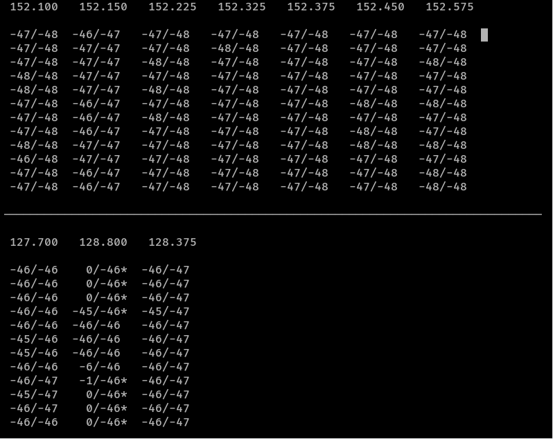
From their wiki: you will see simple text waterfalls, one per each configured channel. This is an example for three devices running in multichannel mode. The meaning of the fields is as follows:

User interface screenshot
  • The number at the top of each waterfall is the channel frequency. When running in scan mode, this will be the first one from the list of frequencies to scan.
  • The number before the forward slash is the current signal level
  • The number after the forward slash is the current noise level estimate.
  • If there is an asterisk * after the second number, it means the squelch is currently open.
  • If there is a > or < character after the second number, it means AFC has been configured and is currently correcting the frequency in the respective direction.

Execute the following command to start running in foreground mode:

# Test in foreground mode
/usr/local/bin/rtl_airband -f

Press Cntrl+C to break out of the stream once you are satisfied with your testing.

Enable RTLSDR-Airband to autostart

To enable RTLSDR-Airband to automatically start up each time your Raspberry Pi is rebooted, you can execute the following commands from within the RTLSDR-Airband directory.

sudo cp init.d/rtl_airband.service /etc/systemd/system
sudo chown root:root /etc/systemd/system/rtl_airband.service
sudo systemctl daemon-reload
sudo systemctl enable rtl_airband
sudo systemctl start rtl_airband

Hurray! We are done!

If you made it this far you have completed all the steps! Enjoy your new streaming SDR solution!

How to add buster-backports to a Raspberry Pi

What are backports?

Debian has a really good write up here on what backports are. Copying directly from their introduction paragraph:

You are running Debian stable, because you prefer the Debian stable tree. It runs great, there is just one problem: the software is a little bit outdated compared to other distributions. This is where backports come in.

Backports are packages taken from the next Debian release (called "testing"), adjusted and recompiled for usage on Debian stable. Because the package is also present in the next Debian release, you can easily upgrade your stable+backports system once the next Debian release comes out. (In a few cases, usually for security updates, backports are also created from the Debian unstable distribution.)

Backports cannot be tested as extensively as Debian stable, and backports are provided on an as-is basis, with risk of incompatibilities with other components in Debian stable. Use with care!

It is therefore recommended to only select single backported packages that fit your needs, and not use all available backports.

Once I enable backports will all packages use them?

No! Any new packages and updates to existing stable packages will prefer the stable releases. The only time you will leverage a new backport package is if you explicitly specify to pull from them.

How do I enable backports?

First you need to add the new backport source to your sources.list file. Edit the file in vi:

sudo vi /etc/apt/sources.list

Arrow down to the last row, press o to create a new line and then enter the following:

deb http://deb.debian.org/debian buster-backports main

Press escape and then type :wq to save the changes and exit via.

Next, we need to specify a keyserver to verify the authenticity of these packages. Note we use Ubuntu's key servers to validate the packages. Interestingly, Debian has a keyring to validate the packages, however the keyring doesn't contain the backports for buster on the raspberry pi at time of writing this. Ubuntu's servers will work fine to validate the authenticity of these packages and you will ultimately pull the packages from Debian rather than Ubuntu.

sudo bash
gpg --keyserver keyserver.ubuntu.com --recv-keys 04EE7237B7D453EC
gpg --keyserver keyserver.ubuntu.com --recv-keys 648ACFD622F3D138

gpg --export 04EE7237B7D453EC | sudo apt-key add -
gpg --export 648ACFD622F3D138 | sudo apt-key add -
exit

How do I obtain a package from backport?

You can leverage one of the follow formats to specify the backport package:

apt install <package>/buster-backports
apt-get install <package>/buster-backports

or

apt install -t buster-backports <package>
apt-get install -t buster-backports <package>

or

aptitude install <package>/buster-backports

How to upgrade Home Assistant Z-Wave integration to Z-Wave JS for Docker

If you've been following my last two tutorials (Home Assistant + Docker + Z-Wave + Raspberry Pi | Jack Stromberg and How to update Home Assistant Docker Container | Jack Stromberg) on running Home Assistant via Docker and how to keep the container updated, you may have noticed that 2021 has been a big year for larger changes, with a surprising change coming to how Home Assistant handles Z-Wave Devices.

In Home Assistant v2021.2, Home Assistant announced the Z-Wave integration as deprecated in favor of a new integration called Z-Wave JS. In Home Assistant v2021.3, many fixes were implemented, with the notable limitation of Door Sensors being removed.

So why the change?

As per the Home Assistant v2021.2 announcement:

More and more people were concerned about the future of Z-Wave with Home Assistant; meanwhile the Z-Wave JS project was rapidly growing and gathering a large community around it. Long story short: Home Assistant and Z-Wave JS teamed up! And a lot of contributors jumped on the train!

This new integration is based on the same base principles as the OpenZWave integration: It is decoupled from Home Assistant. Instead of MQTT, the Z-Wave JS integration uses a WebSocket connection to a Z-Wave JS server.

This means, in order to use this new integration, you’ll need to run the Z-Wave JS server that sits in between your Z-Wave USB stick and Home Assistant. There are multiple options available for running the Z-Wave JS server, via Docker or manually, and there is also a Home Assistant add-on available.

So how do I upgrade?

This article reflects the steps I took to update my Z-Wave implementation.

Ensure you are running Home Assistant v2021.3.2 or greater

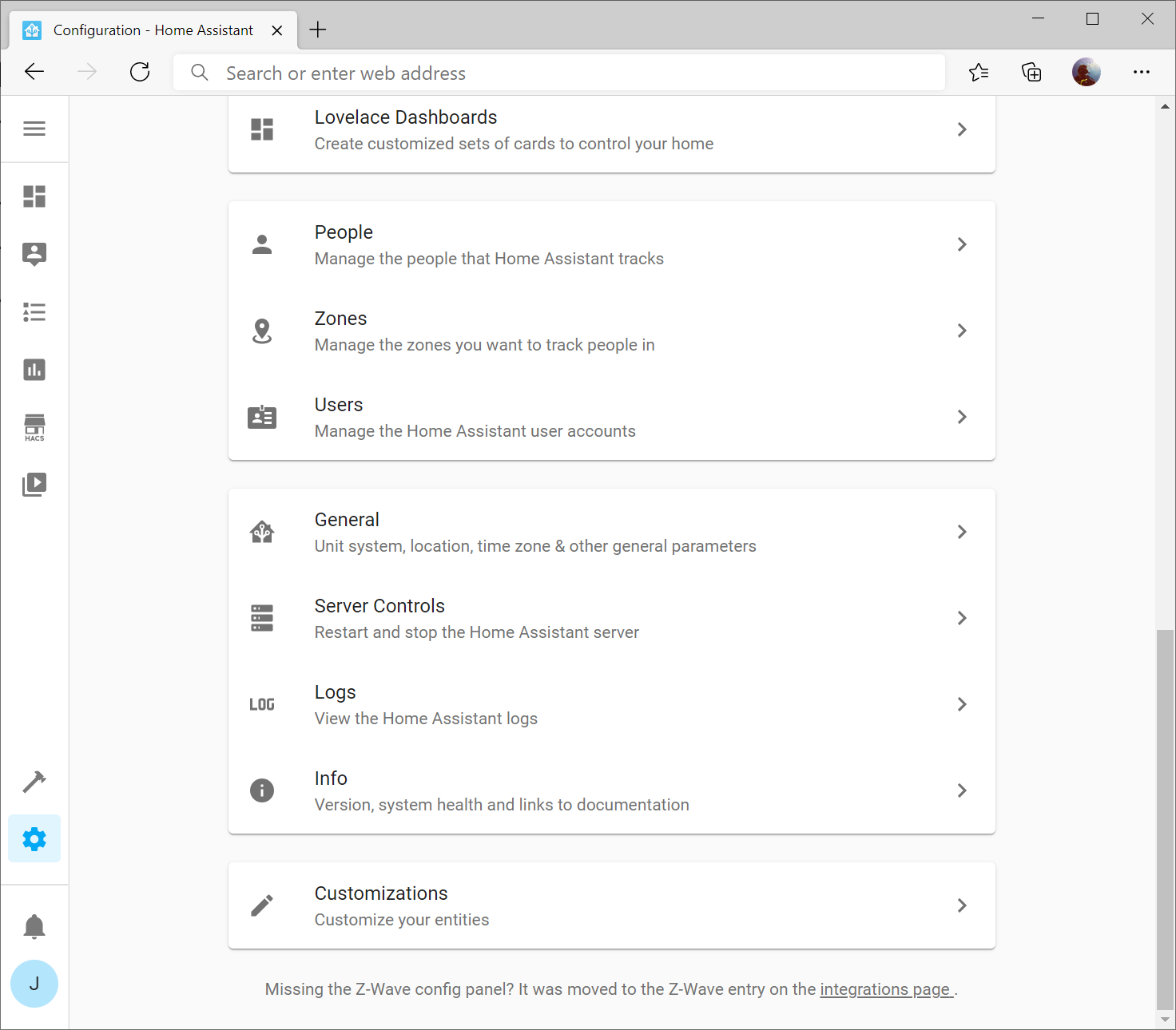
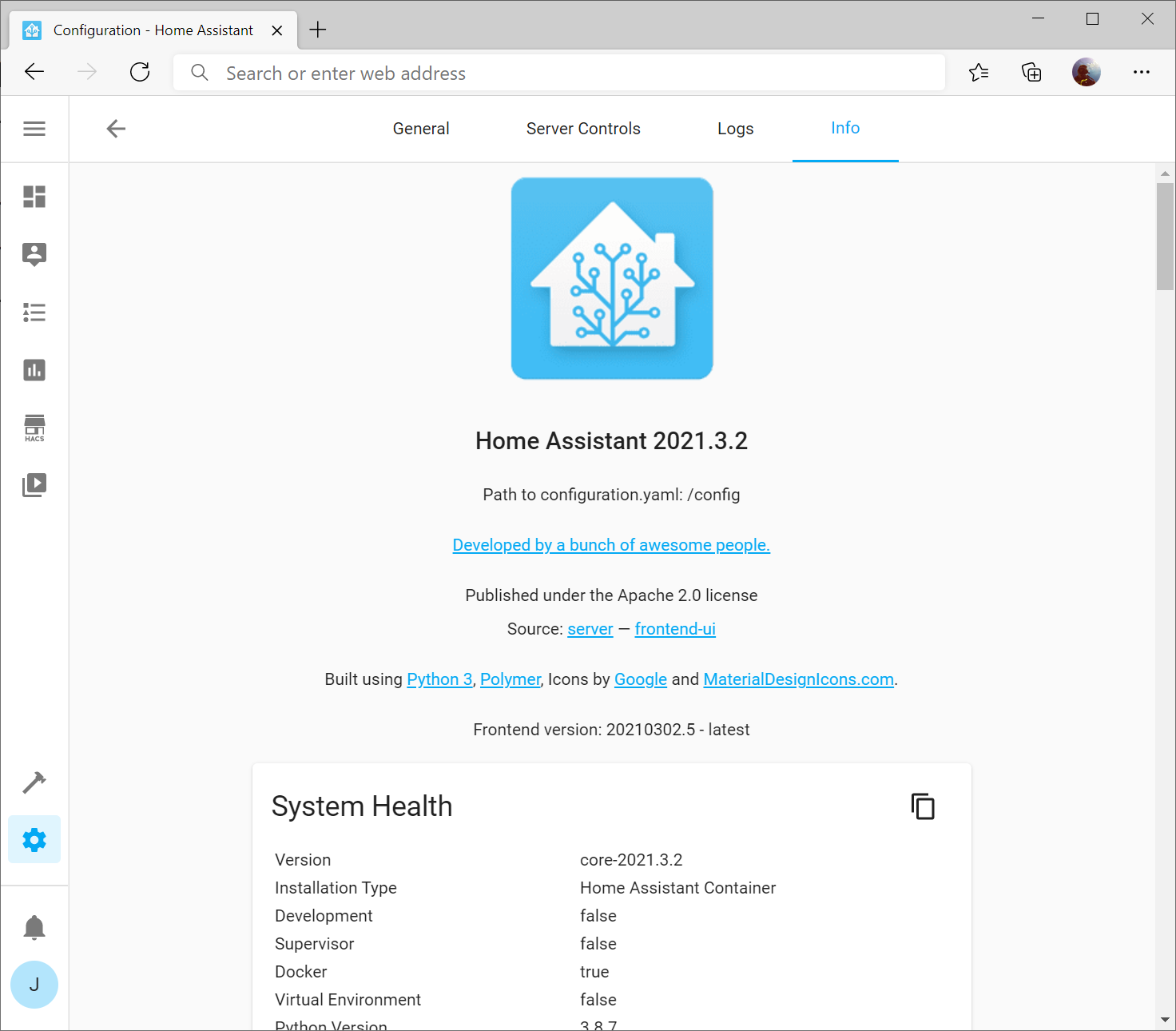
This will ensure you have support for most all sensors. You can find your Home Assistant version by selecting the Configuration gear on the left menu, and then selecting Info

Here you should see the version of Home Assistant (in my case 2021.3.2)

If you are not running the latest version, you can follow my upgrade steps here: How to update Home Assistant Docker Container | Jack Stromberg

Create a backup

It's rather critical to create a backup, especially in this case if you need to roll back to the older OpenZWave integration if you find many of your devices not being compatible. One downside in not using Home Assistant's OS is you don't have the "Supervisor" option to create a full backup.

To complete this step, I'd recommend checking out this blog post here which provides several options: Backing up Home Assistant | Tinkering with Home Automation (ceard.tech)

Alternatively, you can be extremely lazy and less cautious by simply copying the configuration folder containing your docker config:

sudo cp /home/docker/home-assistant/ /home/docker/home-assistant-backup/ -R

Update your Operating System

Execute the following commands against your machine:

sudo sh -c 'apt update && apt upgrade'

Make sure you restart your machine to ensure your kernel updates to the latest version:

sudo shutdown -r -t now

Document Z-Wave entity IDs

The easiest way to do this is to navigate to Developer Tools (hammer icon on the left menu) and then type node_id into the Attributes column's filter.

In this case, you'll want to write down the node_id and the name of the entity it maps to. If you want to do this quickly, you can single click on the table, press Control + A to select all contents, or cmd+a on a Mac, and copy the contents into Word or Excel (Excel works remarkably well).

Document & Comment Z-Wave Stick Hardware ID and Network Key

SSH to your server and find your configuration.yaml file (if using my tutorial it should be /home/docker/home-assistant/configuration.yaml). Open the file in vi

sudo vi configuration.yaml

Find the section of code labeled zwave: and copy the information (we'll need it later) as well as comment out the following lines like so:


#zwave:
#  usb_path: /dev/ttyACM0
#  network_key: "0xAA, 0xBB, 0xCC, 0xDD, 0xEE, 0xFF, 0x00, 0x11, 0x22, 0x33, 0x44, 0x55, 0x66, 0x77, 0x88, 0x99"

Type :wq to write the changes to the file and quit vi

Uninstall Z-Wave integration

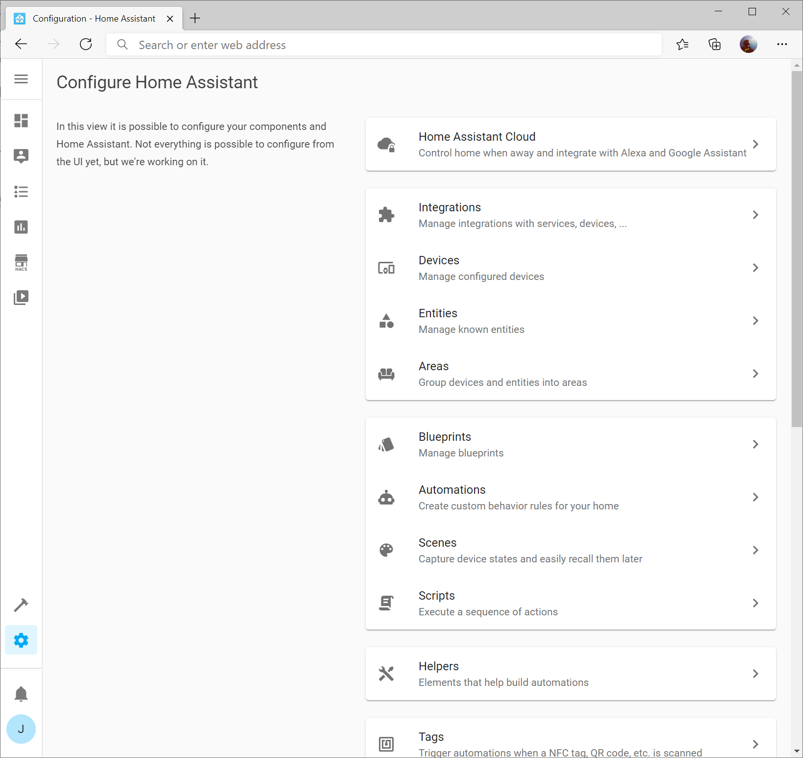
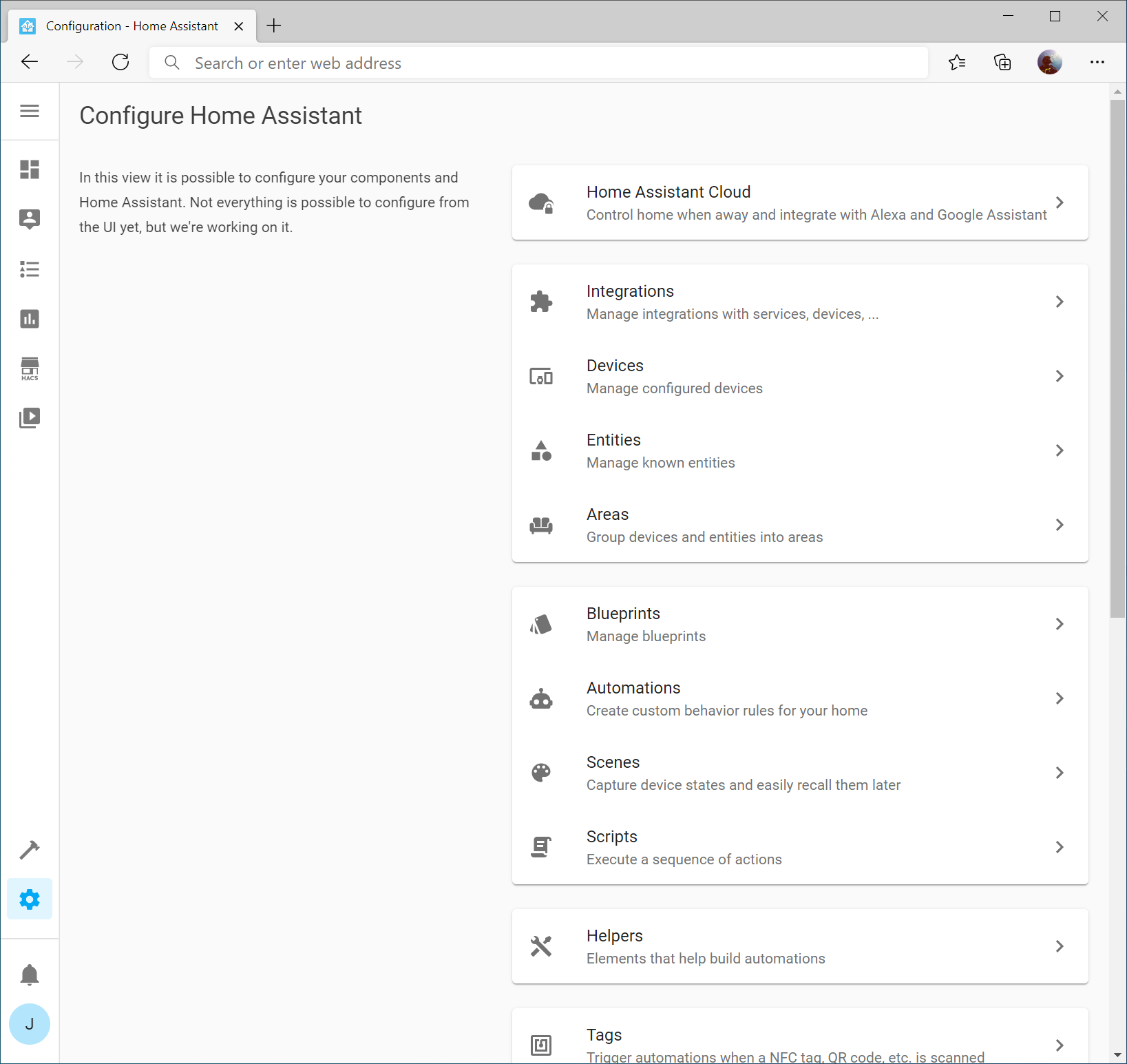
Navigate to Configuration -> Integrations

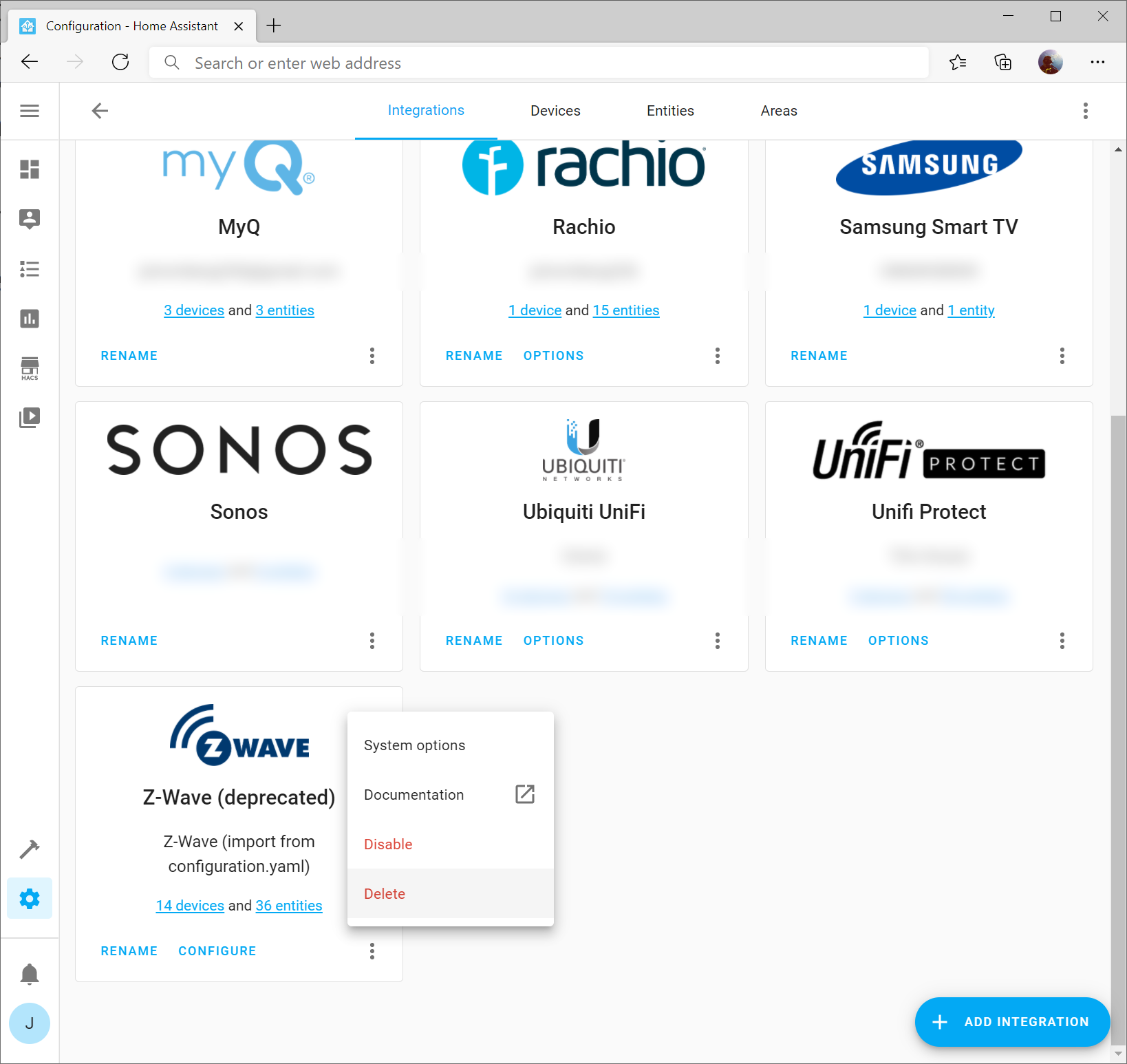
Click the three dots on the Z-Wave integration and select Delete

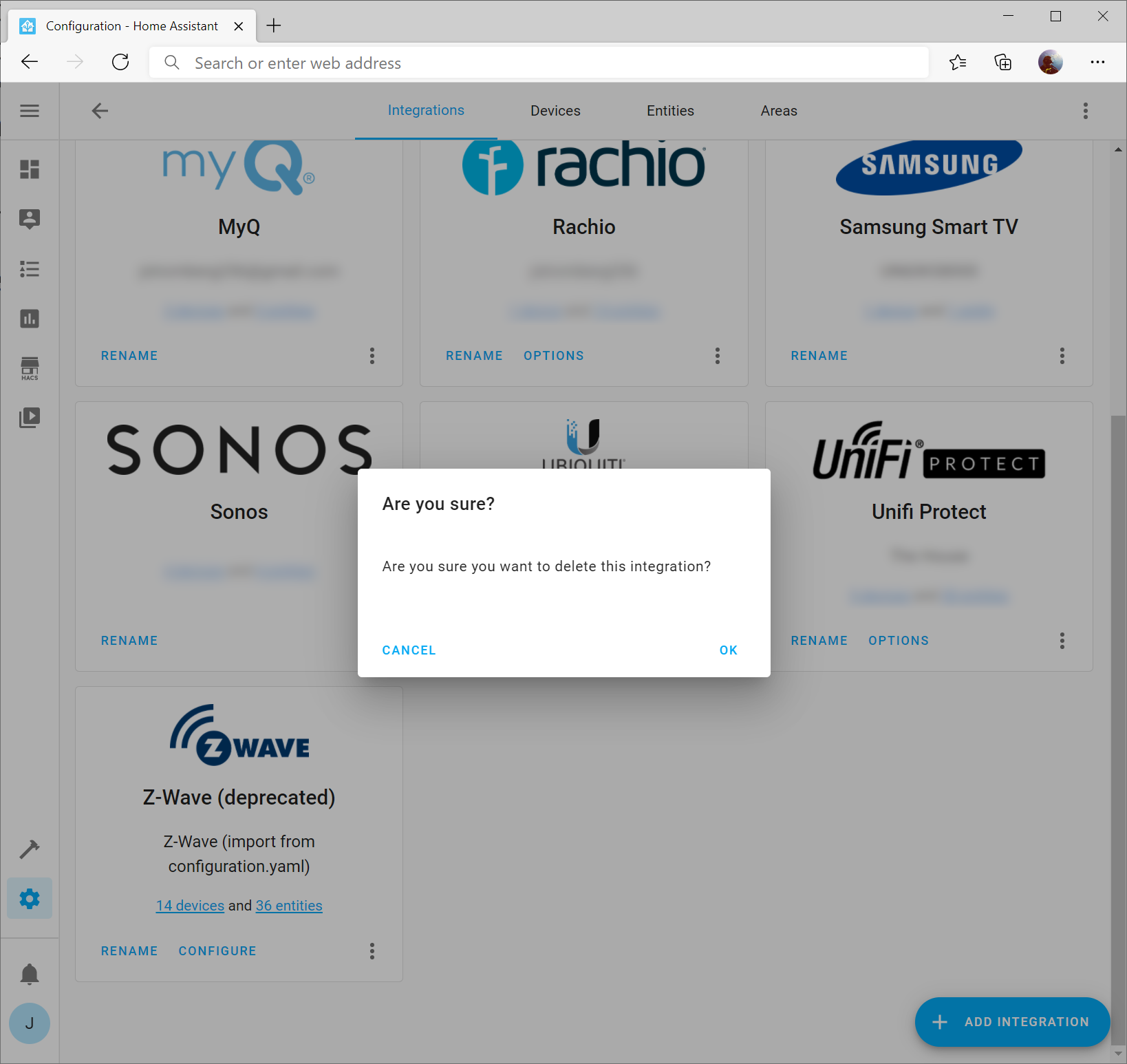
Click OK when prompted

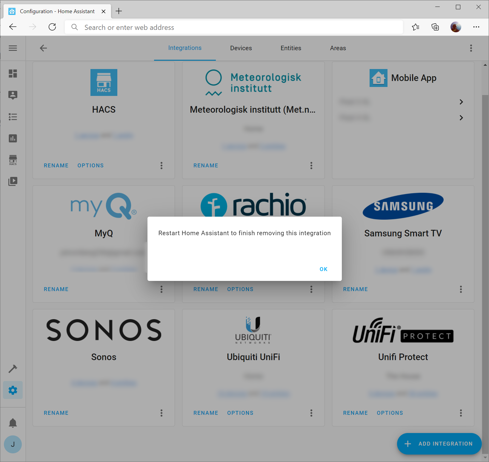
Click OK on the prompt that you should restart home assistant (it won't restart home assistant at this point)

Restart Home Assistant

While we can restart Home Assistant from the web UI, we need to ensure that the Docker container running home assistant no longer needs access to your Z-Wave stick directly (Z-Wave JS Server will be what interfaces with the device directly). In this case, you will need to SSH into your Home Assistant server and stop / remove / start the container accordingly.

Stop the Docker container

sudo docker stop home-assistant

Remove the container

sudo docker rm home-assistant

Deploy the new container configuration, which removes any device mappings to your Z-Wave stick/device

sudo docker run --init -d --restart=always --name="home-assistant" -e "TZ=America/Chicago" -v /home/docker/home-assistant:/config --net=host homeassistant/raspberrypi4-homeassistant:stable

Install Z-Wave JS Server

Create a new directory for the zwave-js server configuration files

sudo mkdir /home/docker/zwave-js/

Run the docker container (the first port listed is for the Z-Wave JS Web Interface, the second port is the Z-Wave JS WebSocket listener)

sudo docker run -d --restart=always  -p 8091:8091 -p 3000:3000 --device=/dev/ttyACM0 --name="zwave-js" -e "TZ=America/Chicago" -v /home/docker/zwave-js:/usr/src/app/store zwavejs/zwavejs2mqtt:latest

Configure Z-Wave JS Server

Navigate to the JS Web Server

http://serverIP:8091/settings

On the settings page, enter the following configuration values (ensuring you substitute in the correct values obtained in the previous steps)

  • Serial Port: /dev/ttyACM0
  • Network Key: AABBCCDDEEFF00112233445566778899
    • Take your existing network key you obtained earlier and remove the 0x and "s to only leave one long hex string. For example:
      • Before
        • 0xAA, 0xBB, 0xCC, 0xDD, 0xEE, 0xFF, 0x00, 0x11, 0x22, 0x33, 0x44, 0x55, 0x66, 0x77, 0x88, 0x99
      • After
        • AABBCCDDEEFF00112233445566778899
  • Log Enabled: Disabled (toggled should be grayed)
  • Commands Timeout: 30 seconds
  • Disable MQTT Gateway: Can be enabled if you have no use for MQTT

Click the Home Assistant menu and set the following:

  • WS Server: Enabled
  • Server Port: 3000

Click SAVE

Verify you see devices

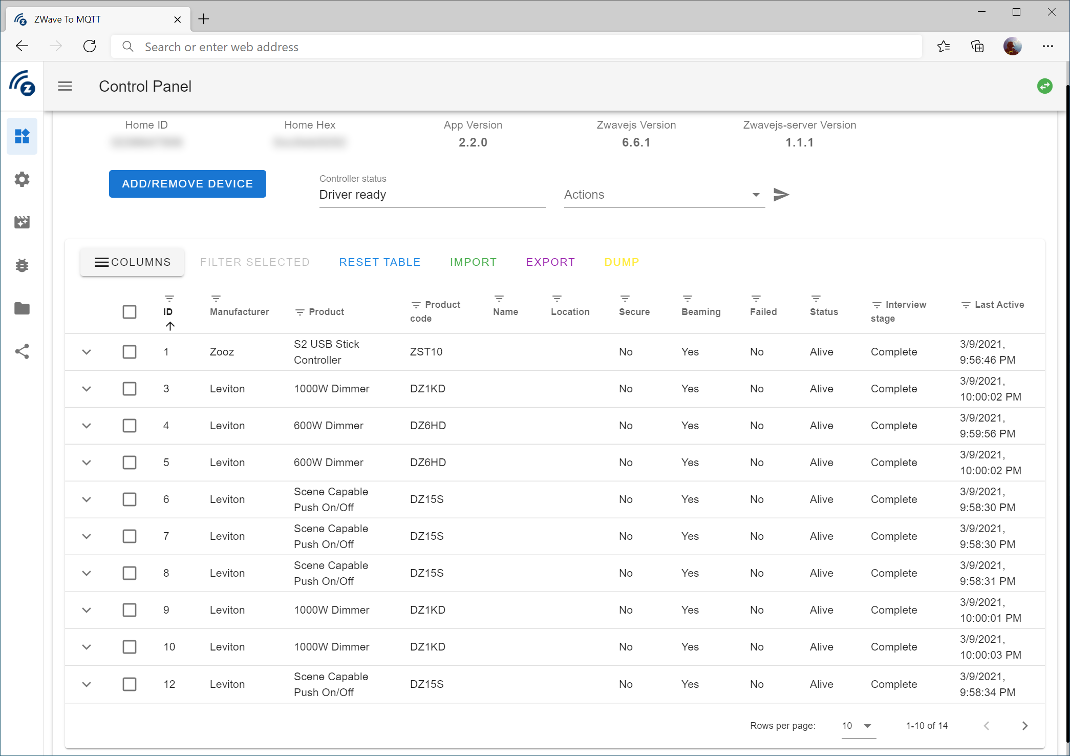
Click on the Control Panel icon on the top left of the Z-Wave JS Web UI. Verify that you see the amount of devices you previously had.

At this point, I would recommend waiting a few minutes / possibly hours to let the table populate with all the device information.

Install Z-Wave JS Integration

I would recommend a full refresh of the web page for Home Assistant and then navigate back to Configuration -> Integrations

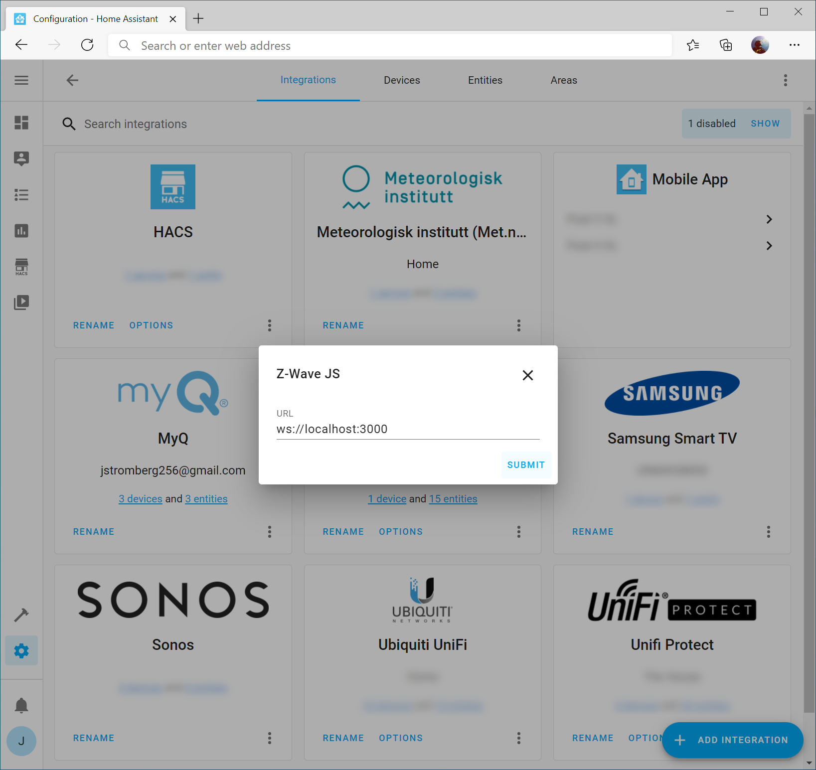
Click the Add Integration button and search for Z-Wave JS

Click Submit to accept the URL as-is (assuming you are running the container on the same server running the Home Assistant container; if not, you can specify the IP address of the server hosting the Z-Wave JS Server container as well).

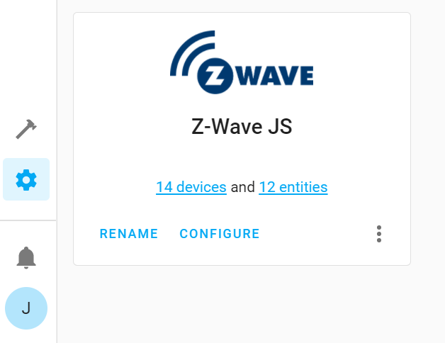
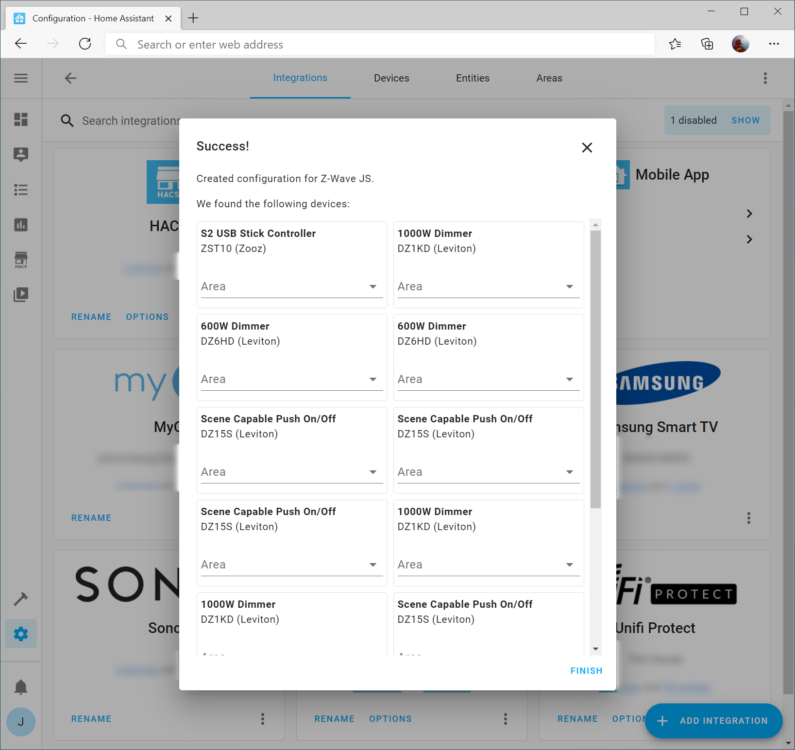
If all went well, you should see your Z-Wave devices and you can click Finish (Note: I wouldn't worry about specifying Areas since it's likely you have no idea what device is what at this point)

Update your Z-Wave Device Names in Home Assistant

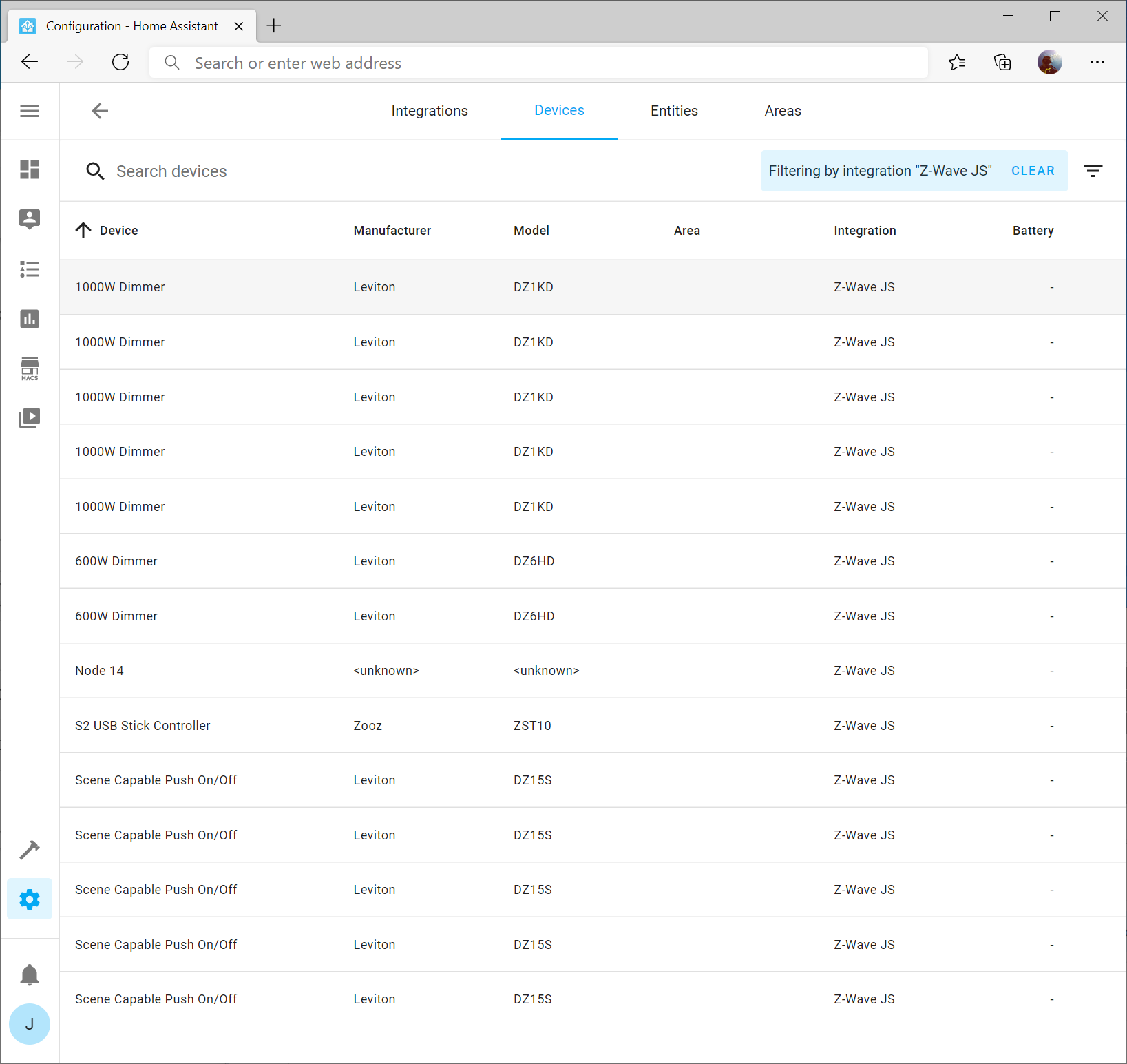
The last step is to update your device names to match your existing device names. To do this, on the Configuration -> Integrations page, select the devices link on the Z-Wave JS integration tile

Next, select one of the items in your list. In my case, I'm going to select the first 1000W Dimmer I have.

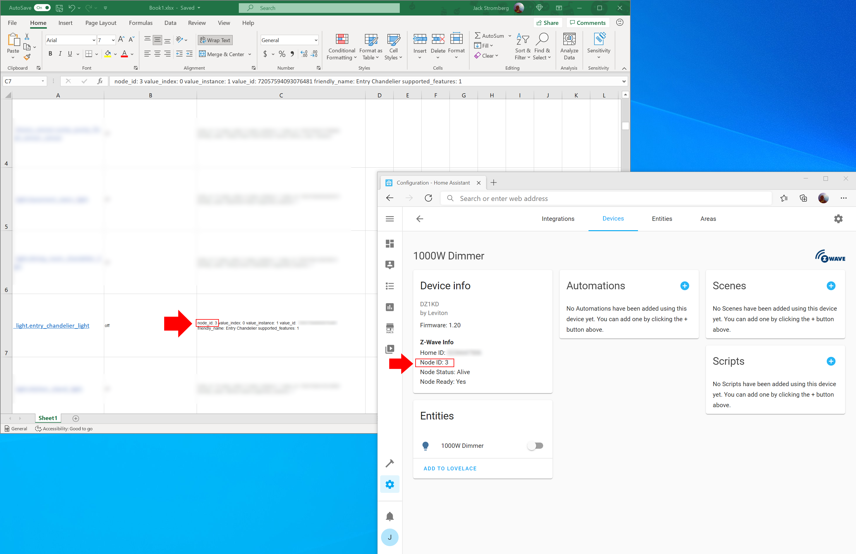
On the device, you should see Node ID. This can be looked up on your list of devices you exported in the previous steps.

Click the Device Name (in my case 1000W Dimmer) and specify the correct information for the device. Once done, click Update

Rinse and repeat

Go through each of the devices you have and update their corresponding names. If you click Advanced settings, you can specify the area for the device as well.

Congrats!

If you've made it this far, you have successfully migrated to the latest Z-Wave integration for Home Assistant!

Home Assistant + Docker + Z-Wave + Raspberry Pi

Notice: Home Assistant has released a new integration called Z-Wave JS. You should be using that integration vs the older Z-Wave integration that this article covers. I will be updating this guide soon.

A few years back I had a SmartThings Hub and for the most part it worked great. It was simple to setup, can be accessed anywhere, and for the most part automatically updated itself. Unfortunately, with the acquisition of it by Samsung, it seems to have turned into bloatware with poor responsiveness, the mobile application's UI is horrific, and they have a less than desirable security/privacy policy.

Luckily, the open source community has thrown together Home Assistant, an open source home automation project backed by hundreds/thousands of individuals. Over the years, they have now brought native support for mobile devices, at time of writing this there are 1500+ integrations for dang near any device, and the software puts you in control of who has access to and where your data is accessible.

The one trade-off though is while Home Assistant works well and is very extensible, the documentation and usability of the application can be overwhelming to understand for someone new to home automation, unfamiliar with Linux/Open Source technologies, or new to debugging/command line interfaces.

In this case, I've tried to document a crash course in getting Home Assistant up and running as quickly as possible for those that want to get started with Z-Wave devices and Home Assistant.

Hardware

You can leverage pretty much any hardware with Home Assistant, but here are the two items I used in my venture. Home Assistant has a full list of recommendations for what hardware to use for Home Assistant (https://www.home-assistant.io/getting-started/#suggested-hardware) as well as what Z-Wave controllers are supported (https://www.home-assistant.io/docs/z-wave/controllers/).

Update your Raspberry Pi

First things first, update your Raspberry Pi with the latest updates. Open up Terminal or SSH to your Raspberry Pi and execute the following command:

sudo apt-get update && sudo apt-get upgrade

Prepare your Z-Wave USB Stick

Plug in your Z-Wave USB stick. Once plugged in, we need to find the device path so that we can reference it for Home Assistant. Execute the lsusb command to find your device ID. In this case, you can see my device ID begins with 0658.

root@raspberrypi:/dev# lsusb
Bus 002 Device 001: ID 1d6b:0003 Linux Foundation 3.0 root hub
Bus 001 Device 003: ID 0658:0200 Sigma Designs, Inc. Aeotec Z-Stick Gen5 (ZW090) - UZB
Bus 001 Device 002: ID 2109:3431 VIA Labs, Inc. Hub
Bus 001 Device 001: ID 1d6b:0002 Linux Foundation 2.0 root hub

Next, let's find what the device path is for the USB stick. You can do this by executing the following command: dmesg | egrep '0658|acm' Please note, if you purchased a difference device, 0658 may be a different number. In this case, you can see my device is presented on ttyACM0.

root@raspberrypi:/dev# dmesg | egrep '0658|acm'
[    1.405327] usb 1-1.2: New USB device found, idVendor=0658, idProduct=0200, bcdDevice= 0.00
[    3.468875] cdc_acm 1-1.2:1.0: ttyACM0: USB ACM device
[    3.471348] usbcore: registered new interface driver cdc_acm
[    3.471359] cdc_acm: USB Abstract Control Model driver for USB modems and ISDN adapters

Install Docker

Home Assistant doesn't require Docker, but by leveraging Docker you can easily copy/backup your configuration and simply redeploy the container if something goes wrong. As updates are made, you can simply remove your container and redeploy. To install Docker, execute the following command:

curl -sSL https://get.docker.com | sh

Deploy Home Assistant Docker Container

Once Docker is installed, you can deploy the container from Docker Hub. Docker Hub is a public repository that has tons of different prebuilt containers to deploy. Here you can find the official homeassistant containers: https://hub.docker.com/u/homeassistant

To deploy the container, execute the following line, replacing the following variables with your desired configuration:

  • --name="the name of your container"
  • -e "TM=YourTimezone"
  • --device=/dev/ttyACM0
    • This allows the container to leverage the Z-Wave USB device. Make sure you specify the path to your device found in the previous step
  • -v /home/docker/home-assistant:/config
    • This is the path that the home assistant configuration files should be stored to. You can specify a fileshare or other path to place your configuration files.
  • --net=host homeassistant/raspberrypi4-homeassistant:stable
    • The first half of this is the container you wish to deploy and the second half is the version. You can find all of Home Assistant's official containers here: https://hub.docker.com/u/homeassistant
sudo docker run -d --restart=always --name="home-assistant" -e "TZ=America/Chicago" --device=/dev/ttyACM0 -v /home/docker/home-assistant:/config --net=host homeassistant/raspberrypi4-homeassistant:stable

Note: In newer versions of the docker container --init should not be specified in the docker run command. Specifying --init will result with the following error: "s6-overlay-suexec: fatal: can only run as pid 1". This was mentioned as a breaking change in: 2022-06-01 update: 2022.6: Gaining new insights! - Home Assistant (home-assistant.io)

Setup Home Assistant

Give the container a few minutes to deploy and configure itself for the first time. After a few minutes, try opening your web browser and navigating to the IP address assigned to your machine, using port number 8123: http://192.168.1.2:8123/

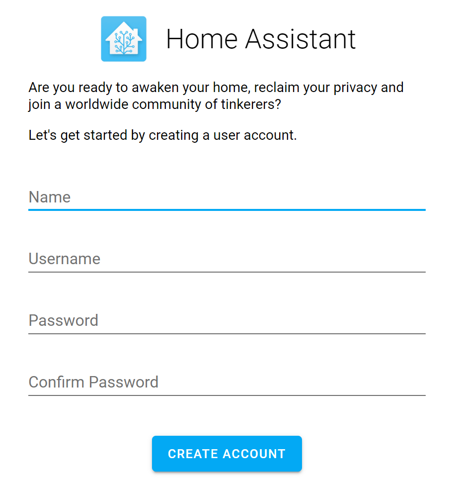
When the page loads, it should first ask for your Name, Username, and Password. This is the username and password you will use to login to Home Assistant.

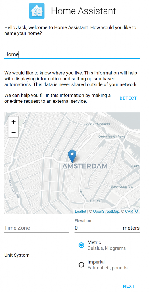
Next, specify the location of where your Home Assistant deployment is located. Oddly enough, you cannot type in a location, but you can place the pin near your location by dragging the map around and clicking once to set the pin.

Once you click Next, Home Assistant may have already found a few devices connected to your network. You can add them now or skip and add them later.

Tell Home Assistant to use your Z-Wave USB Stick

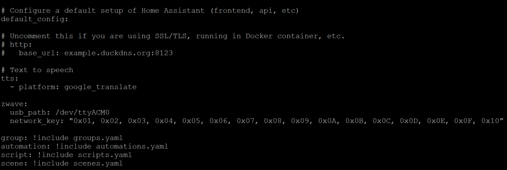
Although we granted access to the container to use the Z-Wave USB Stick, you need to tell Home Assistant how to leverage the device. To do so, you will need to open up Terminal or SSH to your machine and edit the configuration.yaml file to point to the device. Before we get into modifying the configuration.yaml file, first execute the following command to generate a Z-Wave Security Key. This key may be required by Z-Wave security devices (Door Locks, Keypads, etc), as an extra layer of security. More information on this can be found here: https://www.home-assistant.io/docs/z-wave/adding#network-key

Execute the following command via Terminal or SSH:

cat /dev/urandom | tr -dc '0-9A-F' | fold -w 32 | head -n 1 | sed -e 's/\(..\)/0x\1, /g' -e 's/, $//'

Once you execute the command, it should give you a string of characters that look something like:

"0x01, 0x02, 0x03, 0x04, 0x05, 0x06, 0x07, 0x08, 0x09, 0x0A, 0x0B, 0x0C, 0x0D, 0x0E, 0x0F, 0x10"

Next, we need to edit the configuration.yaml file, which can be found in the path specified when the Docker container was deployed (using the -v parameter). For the purpose of this article, /home/docker/home-assistant/configuration.yaml is where the file is located. Using your favorite text editor, add the following lines of code:

zwave:
  usb_path: /dev/ttyACM0
  network_key: "0x01, 0x02, 0x03, 0x04, 0x05, 0x06, 0x07, 0x08, 0x09, 0x0A, 0x0B, 0x0C, 0x0D, 0x0E, 0x0F, 0x10"
configuration.yaml file with Z-Wave configuration

Once saved, go back to Home Assistant and click the Gear icon and then select Server Controls

Select the Restart button to restart Home Assistant. Any time you make a change to the configuration.yaml file, you will need to restart Home Assistant to pickup the configuration changes.

Click OK to Restart

Upon restart, navigate back to the Gear icon and you should see a new entry in the Config portal for Z-Wave. If you do not see the "Z-Wave" section, scroll down to the troubleshooting step at the end of this article.

Add a Z-Wave device

Once you see that your Z-Wave network has started, adding a device is a piece of cake. First click the Add Node button. When you click the button, nothing will happen, but go ahead and put your device in inclusion mode. Once the device is in inclusion mode, Home Assistant should automatically add the device.

At this point, if you navigate back to Configuration (Gear icon) and select Devices

You should see your newly added Z-Wave device!

At this point, you can select the Device to give it a friendly name or start to work on building your own home automation actions.

Hope this helped! If you have any comments or suggestions on how to improve this guide, please drop it below.

Troubleshooting Missing Z-Wave Configuration

The first time I ran through this, I noticed I was missing the Z-Wave configuration tile after making changes to the configuration.yaml file. It turned out I specified the wrong device path in the configuration file. To verify, you can check the logs from your Docker container by executing the following command in your Terminal or via SSH. (Replace home-assistant with the name of your container if you specified something else)

sudo docker logs home-assistant

In my case, I had the following error:

2020-02-16 21:08:01 INFO (MainThread) [homeassistant.components.scene] Setting up scene.homeassistant
2020-02-16 21:08:02 INFO (MainThread) [homeassistant.components.zwave] Z-Wave USB path is /dev/ttyACM01
2020-02-16 21:08:02 ERROR (MainThread) [homeassistant.config_entries] Error setting up entry Z-Wave (import from configuration.yaml) for zwave
Traceback (most recent call last):
  File "/usr/local/lib/python3.7/site-packages/openzwave/option.py", line 78, in __init__
    raise ZWaveException(u"Can't find device %s : %s" % (device, traceback.format_exception(*sys.exc_info())))
openzwave.object.ZWaveException: "Zwave Generic Exception : Can't find device /dev/ttyACM01 : ['NoneType: None\\n']"

During handling of the above exception, another exception occurred:

Traceback (most recent call last):
  File "/usr/src/homeassistant/homeassistant/config_entries.py", line 215, in async_setup
    hass, self
  File "/usr/src/homeassistant/homeassistant/components/zwave/__init__.py", line 369, in async_setup_entry
    config_path=config.get(CONF_CONFIG_PATH),
  File "/usr/local/lib/python3.7/site-packages/openzwave/option.py", line 81, in __init__
    raise ZWaveException(u"Error when retrieving device %s : %s" % (device, traceback.format_exception(*sys.exc_info())))
openzwave.object.ZWaveException: 'Zwave Generic Exception : Error when retrieving device /dev/ttyACM01 : [\'Traceback (most recent call last):\\n\', \'  File "/usr/local/lib/python3.7/site-packages/openzwave/option.py", line 78, in __init__\\n    raise ZWaveException(u"Can\\\'t find device %s : %s" % (device, traceback.format_exception(*sys.exc_info())))\\n\', \'openzwave.object.ZWaveException: "Zwave Generic Exception : Can\\\'t find device /dev/ttyACM01 : [\\\'NoneType: None\\\\\\\\n\\\']"\\n\']'

Here you can see I accidentally specified /dev/ttyACM01 vs /dev/ttyACM0. Simply updating the configuration.yaml file with the correct device path solved the issue.

Setting up a new Raspberry Pi via SSH

This is my super subpar tutorial on how to quickly setup a new Raspberry Pi via SSH (no mouse/keyboard/monitor directly attached to the device).

  1. Download the latest copy of the operating system (I personally prefer Raspbian Stretch Lite for the most minimal setup): https://www.raspberrypi.org/downloads/raspbian/
  2. Extract the download so you have a copy of the ****-**-**-raspbian-stretch-lite.img file
  3. Download Etcher to burn the image to an SD Card: https://etcher.io/
  4. Download a copy of Putty if you don't have a way to ssh: https://www.chiark.greenend.org.uk/~sgtatham/putty/latest.html
  5. Open the SD card you just flashed and you should see the "boot" partition.  Create a file called ssh (no file extension or data needs to be written to the file)
    1. Note: ssh is disabled on all OS builds starting November 16 forward -- see here: https://www.raspberrypi.org/documentation/remote-access/ssh/
  6. Default credentials:
    1. Username: pi
    2. Password: raspberry
  7. Quick commands
    1. Configure Raspberry PI specific settings: sudo raspi-config
    2. Proper Shutdown (-h) / Restart (-r): sudo shutdown -h now

Unlike most laptops/desktops, the Raspberry Pi doesn't have a shutdown button, so always use the commands above to prevent SD Card corruption!