Category Archives: Uncategorized

Revitalizing your Tesla AP1 vehicle with openpilot

There are a ton of old Teslas out there running Autopilot v1 (AP1), and they fall further behind in assisted-driving capability every year. AP1 felt ultra futuristic in its day, but it’s starting to become outclassed even by the lane assist shipping in everyday non-Tesla cars.

One of the biggest reasons I opted to seek an upgrade was the ability to remove the notorious “Tesla NAG”. While I get checking if the driver is paying attention is critical for safety, the way Tesla did it in AP1 was less than ideal by having to apply torque to the steering wheel, even if you are alert and watching the road ahead of you. In addition, the driving capabilities of AP1 on unmarked roads, aggressive curves, phantom braking, etc. make for a significantly less confident driving experience in AP1 and feel dated compared to newer vehicles today.

openpilot – make driving chill

Revive your car with the open source software openpilot, maintained by the company Comma AI! comma.ai — make driving chill

While Comma AI does not officially support old Tesla vehicles there are several forks for older Teslas to use openpilot and while Comma AI doesn’t provide an official wiring harness for older Tesla cars, they do provide a developer harness where you can make your own.

You can grab a harness for the vehicle from a developer in the openpilot community, who has helped try to maintain a fork of openpilot (which we’ll talk about later on). This makes installing the Comma 4 significantly easier by bringing peace of mind it’s correct and kick back support to the maintainer for their contributions to the fork for the older Tesla vehicles.

That being said, I went down the road of trying to DIY this myself for a few reasons:
1) I wanted to learn.
2) There have been many contributors to the Tesla AP1 effort and at time of writing this, there is only one individual making harnesses. If that individual decides to take on a new project, that makes new harnesses for Tesla AP1 vehicles impossible to source (supply chain risk). In the spirit of open source, IMO, the harness details should be available to keep the vehicle support available for future reference.
3) I wanted to use Comma supplied products as much as possible to have as close to what an official solution might be as possible.
4) I had many of the tools needed to make the harness and could do it for significantly less.

When starting the project, cost wasn’t originally my concern, but I was lucky and was able to pick up their official developer harness for $50 on sale and with sourcing the parts and ultimately was able to make it for under $100. The prebuilt harness was > $250 and my understanding at the time is it would have shipped from Europe, so it would have likely gone over $300 with tariffs with that assumption (although they have some stock in the USA I found out later on).

While a cheaper harness sounds great, one big note is if you go down the DIY route, don’t expect the Comma community to help. The folks that really understand this kind of stuff in the unsupported Tesla community really laid it on thick that I should give up and just buy the harness.

IMO, if you have the time and patience it was an interesting project and I learned a lot on the electrical side and comma side debugging the pin configuration.

Nonetheless, if you do this DIY, don’t expect much help. If you just want your car to work, buy the harness, it’s worth it. If you have some background in software development and electrical engineering, then here’s my learnings if you want to take a similar venture; but proceed at your own risk. I’m not responsible if you short out any components of your car.

Acquiring the parts for the harness if you DIY this

You can grab an official developer harness from Comma AI’s shop here: https://comma.ai/shop/car-harness?harness=Developer.

These are the parts from Digikey needed to make the harness:

Qty 2: MQS 8P PLUG HSG BLK – 17-1-1743282-2-ND

Qty 2: MQS HDR 8P ASSY(H-TYPE) BLK – 17-1-1743284-2-ND

Qty 20: MQS REC CONT – 17-5-963715-1CT-ND (You only need 16, but they are cheap and if you’ve never crimped these, grab a few extra for practice)

Qty 1: Breakable Protoboard: I used this to connect/solder the two MQS HDR 8P ASSY modules together: 1568-13268-ND

Qty 2: Hookup wire between 22AWG and 26AWG – I had some hookup wire on hand (3175 Adafruit Industries LLC | Cables, Wires – Single Conductors Kits | DigiKey), but you could buy per foot as well: 30-01780 Tensility International Corp | Single Conductor Cables (Hook-Up Wire) | DigiKey and 55A0111-26-9 TE Connectivity Raychem Cable Protection | Single Conductor Cables (Hook-Up Wire) | DigiKey

Qty 1: Electrical tape – Ideally, you could also use heat shrink tubing if you have some that’s 1.25″ wide.

Misc from Amazon

Qty 1: Wiring harness tape – not required, but can help with longevity of your cable.

Note: this guide assumes you have solder, soldering iron, and wire strippers on hand. I’d recommend an adjustable wire stripper as getting the lengths to the connectors can be tricky by hand, but if you are buying this just to make the cable, you may as well buy the prebuilt harness since you are likely getting close to breaking even: 12 40 200 Knipex Tools LP | Wire Strippers and Accessories | DigiKey

The pinout of the harness

First, familiarize yourself with the Comma AI dev harness. The pinout for it can be found here: https://github.com/commaai/hardware/blob/master/harness/v3/Developer_Harness.pdf
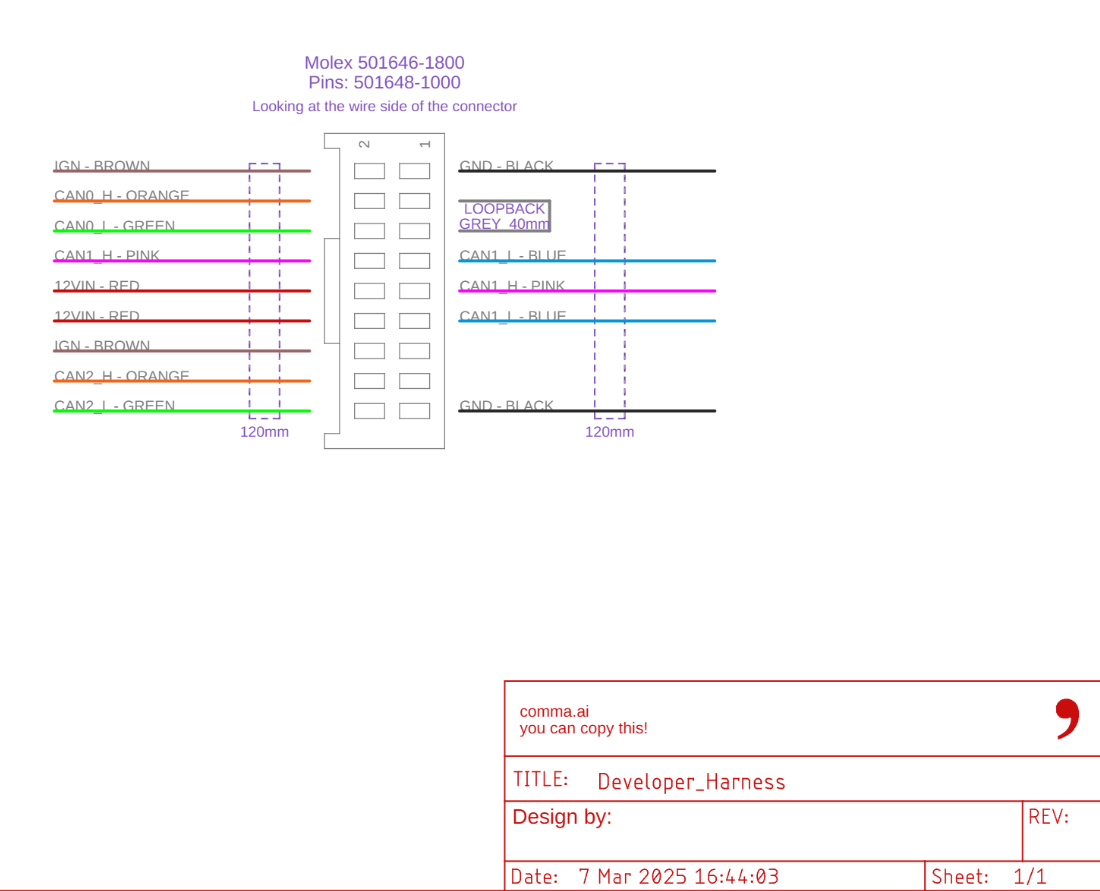
Next, understand the Tesla harness. Tesla has a copy of the Forward Camera (NCAP) harness here:
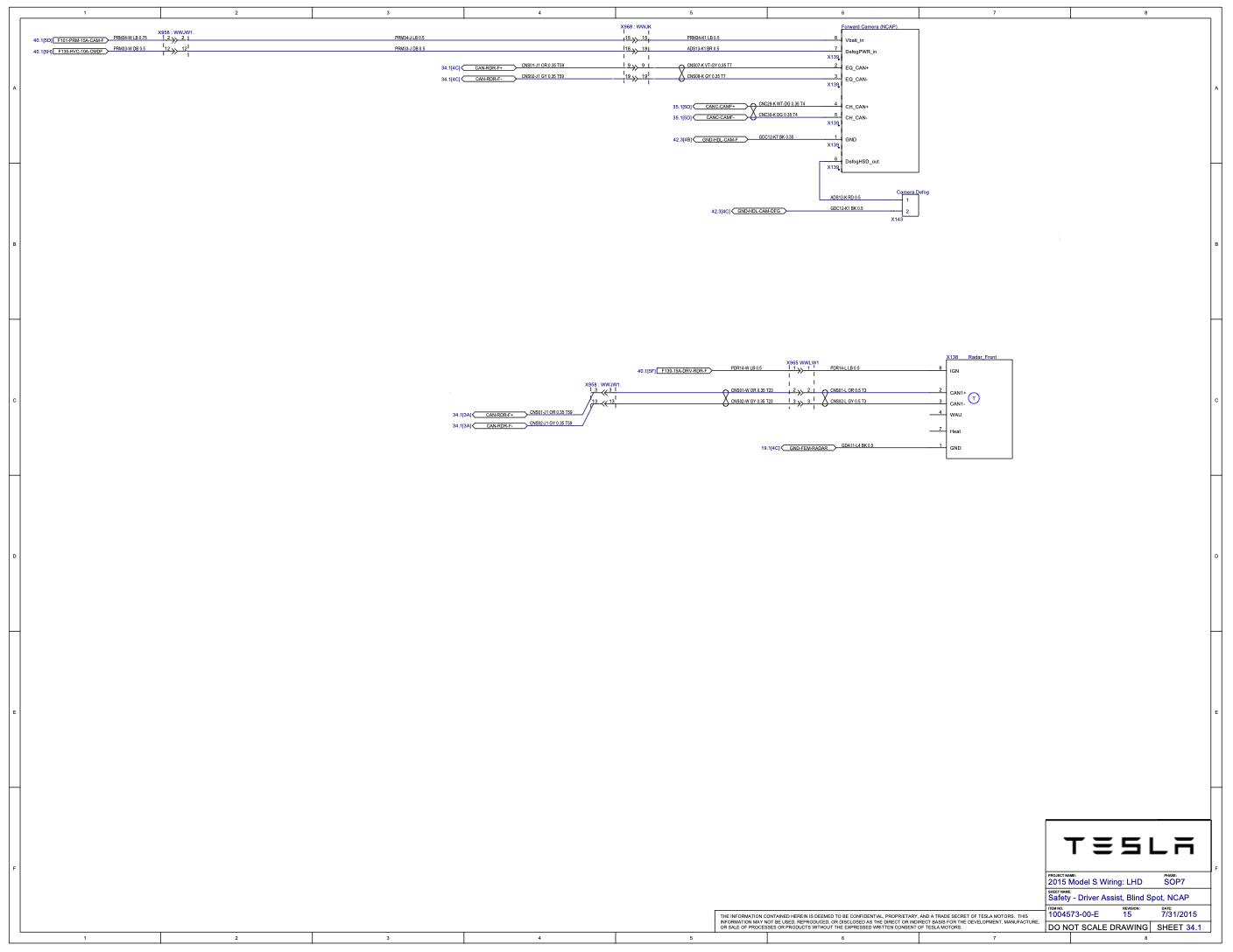
https://service.tesla.com/docs/ModelS/ElectricalReference2012/s-lhd-sop7/2015.1_ModelS_LHD_Release.pdf

Pulling it altogether, you get this as the secret sauce to build the harness:

This branch of your harness is what receives the connector from the car (connector originally going to the Forward Camera (NCAP) port).

Connector to car
(MQS 8P PLUG HSG)
[Connects to the Tesla cable]
SignalComma DEVELOPER harness pin
Pin 8GNDPin 1
Pin 7Radar CAN +Pin 8
Pin 6Radar CAN −Pin 7
Pin 5Camera CAN +Pin 4
Pin 4Camera CAN −Pin 6
Pin 3DefogHSD_OUTPassthrough to mirror pin 6
Pin 2DefogPWR_inPassthrough to mirror pin 7
Pin 1+12VPin 10

This branch of your harness is what plugs into the Forward Camera (NCAP) port.

Connector to mirror
(MQS 8P PLUG HSG)
[Connects to mirror port]
SignalComma DEVELOPER harness pin
Pin 1GNDPin 17
Pin 2Radar CAN +Pin 9
Pin 3Radar CAN −Pin 11
Pin 4Camera CAN +Pin 16
Pin 5Camera CAN −Pin 18
Pin 6DefogHSD_OUTPassthrough to car pin 3
Pin 7DefogPWR_inPassthrough to car pin 2
Pin 8+12VPin 12

Pin 3 and 5 are looped on the comma developer harness connector (this is standard to the dev harness as-is)

The two IGN cables (brown cables at time of writing) that come with the dev harness you can remove as they won’t be used. You can use a tiny flat head screwdriver to gently lift the flap holding the connector to the cable up while pulling on the cable to slide them out.

For Pin 6 and 7 that passthrough to other connector, those map to the defog control of the mirror and can skip connecting to the Comma developer harness. The developer harness uses 26 AWG wire if you want to match their wire size. I used White and Dark gray cables to try and differentiate from the colors used in the Comma dev harness, but the color of shielding isn’t going to make a difference electrically lol

One note about this, be very very very careful you do not mix up the 12v pins with another position when building your harness. If you send 12v down your CAN buses, that will not be good. Use a multimeter to triple check. I was ultra surprised to find that Tesla had a red wire on their harness and it didn’t carry 12v; rather the “blue” wire is what actually carried 12v. Going simply by the color codes would have given me a bad day, so DO NOT make any assumptions.

When building my harness, I terminated both the “to car” and “to camera” cables with the MQS 8P plugs. Connecting the cable from the car to the comma, I placed both MQS HDR 8P ASSY back-to-back on the protoboard and soldered the pins together. This allowed me a secure connection between the car and comma harness. Unfortunately, TE Connectivity doesn’t have the receiving connector without it being mounted to a PCB board, so double connector it was. Given vibration and force from accelerating / braking, I’d recommend locking connectors over the screw down blocks to prevent wires from coming loose.

Harness Creation

Break away 2 rows of 10 pins from your protoboard. If having a tough time snapping the protoboard apart, you can use a utility knife or exacto knife to score the area you want to snap; then use a needle nose pliers to wiggle the board back and forth until it breaks away. I used 10 pins worth, with one pin on each side unused, to give the connector a little more rigidity. Place the HDR 8P ASSY adapters back to back and solder them together.
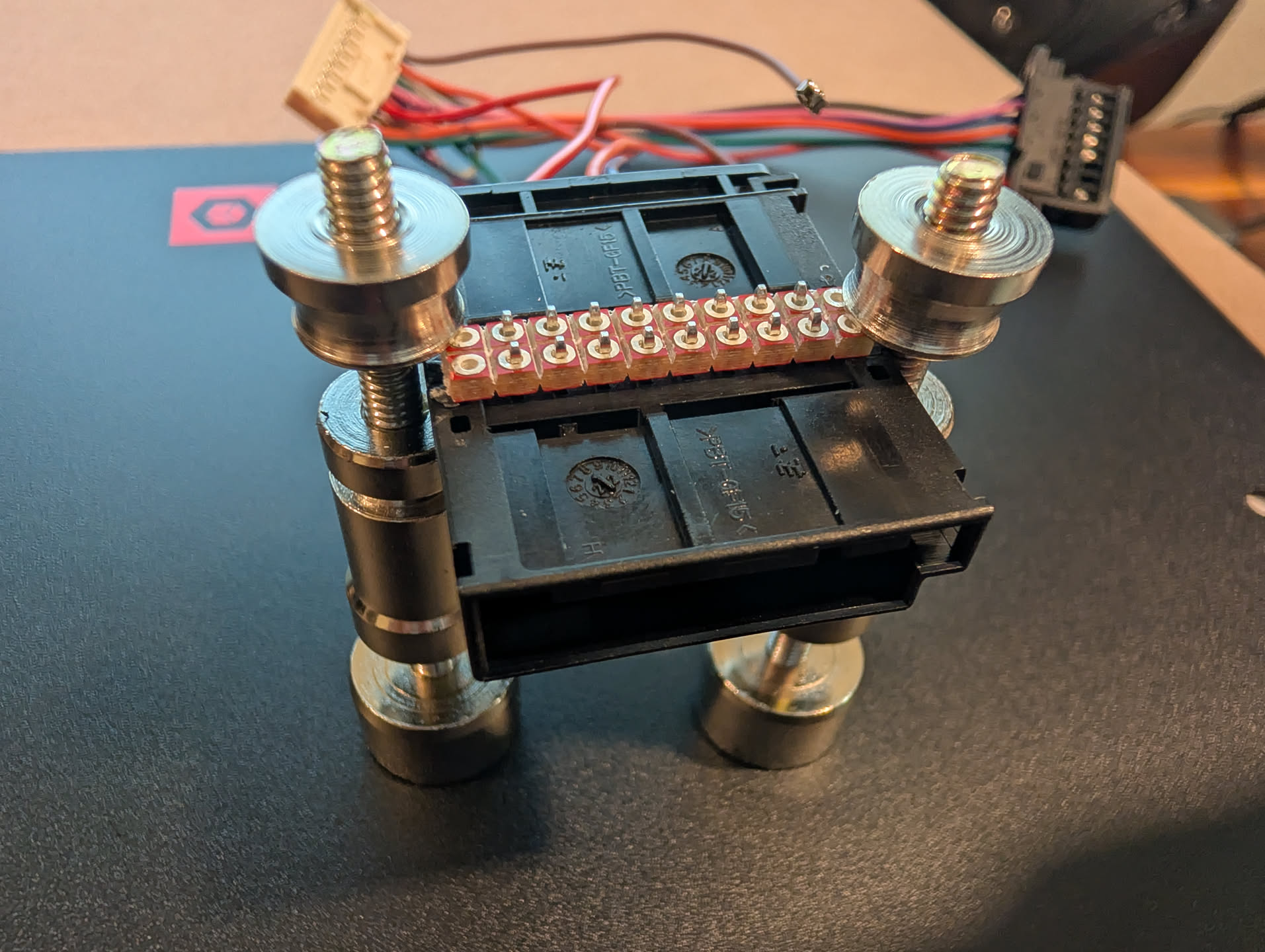
Remove the 2 IGN pins from the comma harness since they won’t be used and add the MQS rectangular pins to each of the wires needed for the harness.
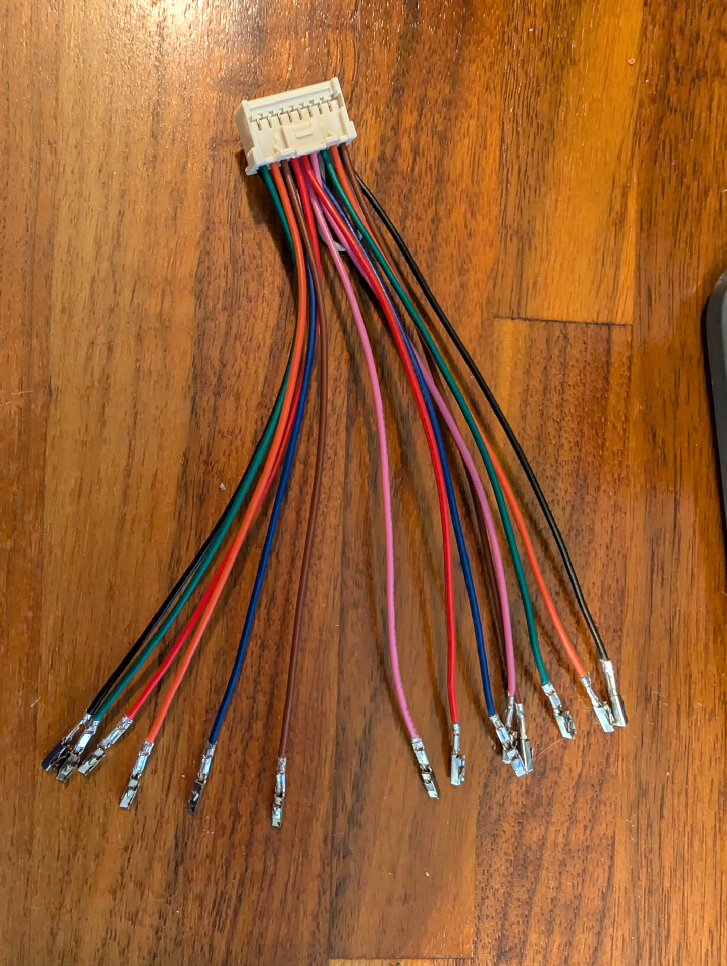
Connect the wires to each of the MQS 8P PLUG HSG adapters.

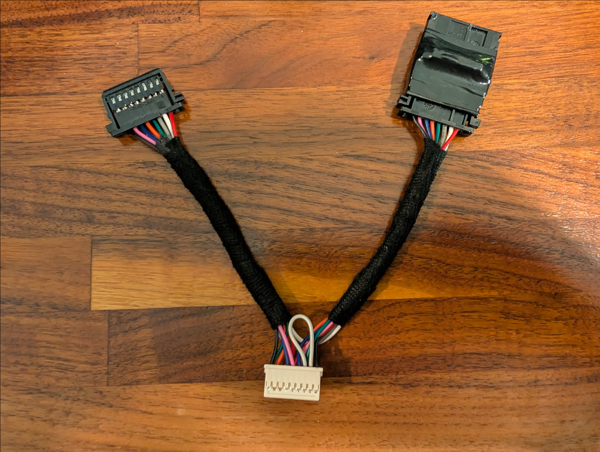
Add the fabric tape around the two branches of the harness and added electrical tape around the two HDR 8P ASSY adapters to insulate the soldered pins.
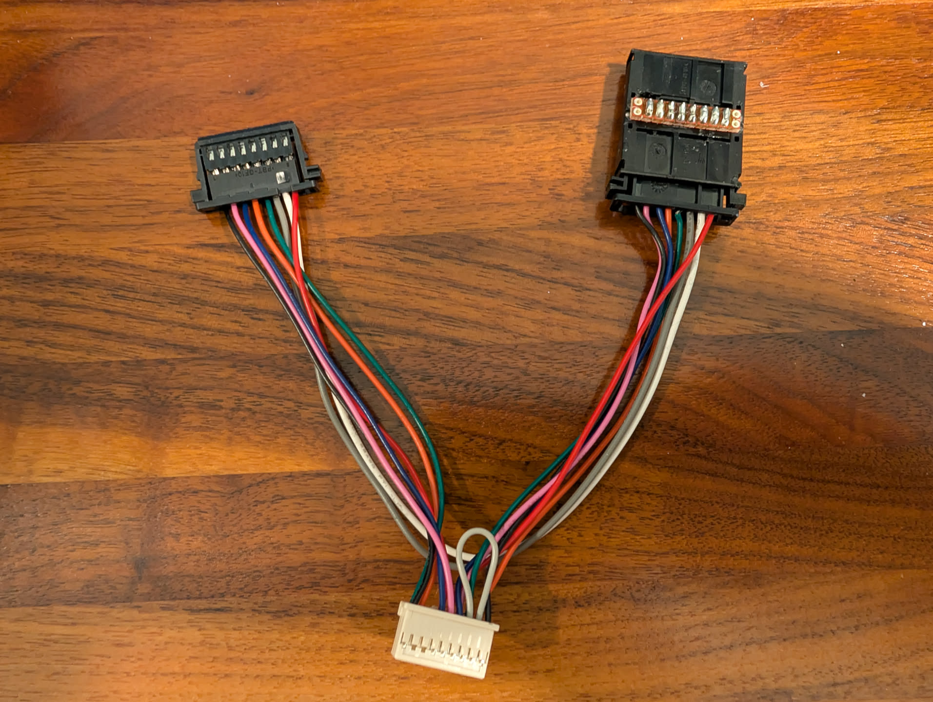
Final harness should look something like this:
Mount the Comma 4 Bracket

Before you pull apart your mirror, I would recommend mounting the Comma 4 bracket. Sit how you would normally in your seat, then hold the device up. The camera can be partially blocked by the mirror, but not fully. I saw a guide that said use 3 fingers down and you should be good. I did more like 4-5, since 3 had the entire device completely blocked by the mirror. Once your Comma 4 is mounted, remove the Comma 4 itself from the device, leaving just the mount on your windshield. One thing to make sure is to make sure the yaw (left and right balance) of the unit is as close as level as possible; you have roughly 4 degrees of skew and it’s nearly impossible to adjust once you stick the device, so have someone take a look on the outside of the windshield to gauge if it looks aligned properly.

Install the harness

To install the harness you will need to remove the front mirror assembly. Official instructions can be found on Tesla’s website here:

https://service.tesla.com/docs/ModelS/ServiceManual/en-us/GUID-090CC4A1-9427-4E59-B021-74488A5C74DE.html

If you prefer a YouTube video, this video was helpful on understanding how to remove the mirror (don’t go past moving the mirror):

Mount the Comma 4 and Connect the harness

With the mirror assembly removed, unplug the connector to the mirror by pushing in both of the black sides of the connector and adding a pushing motion away to try and leverage the connector out. I found using two small flathead screwdrivers to push in the side tabs while trying to scoot the connector out worked the best. It’s tricky and can be frustrating, but you can get it!
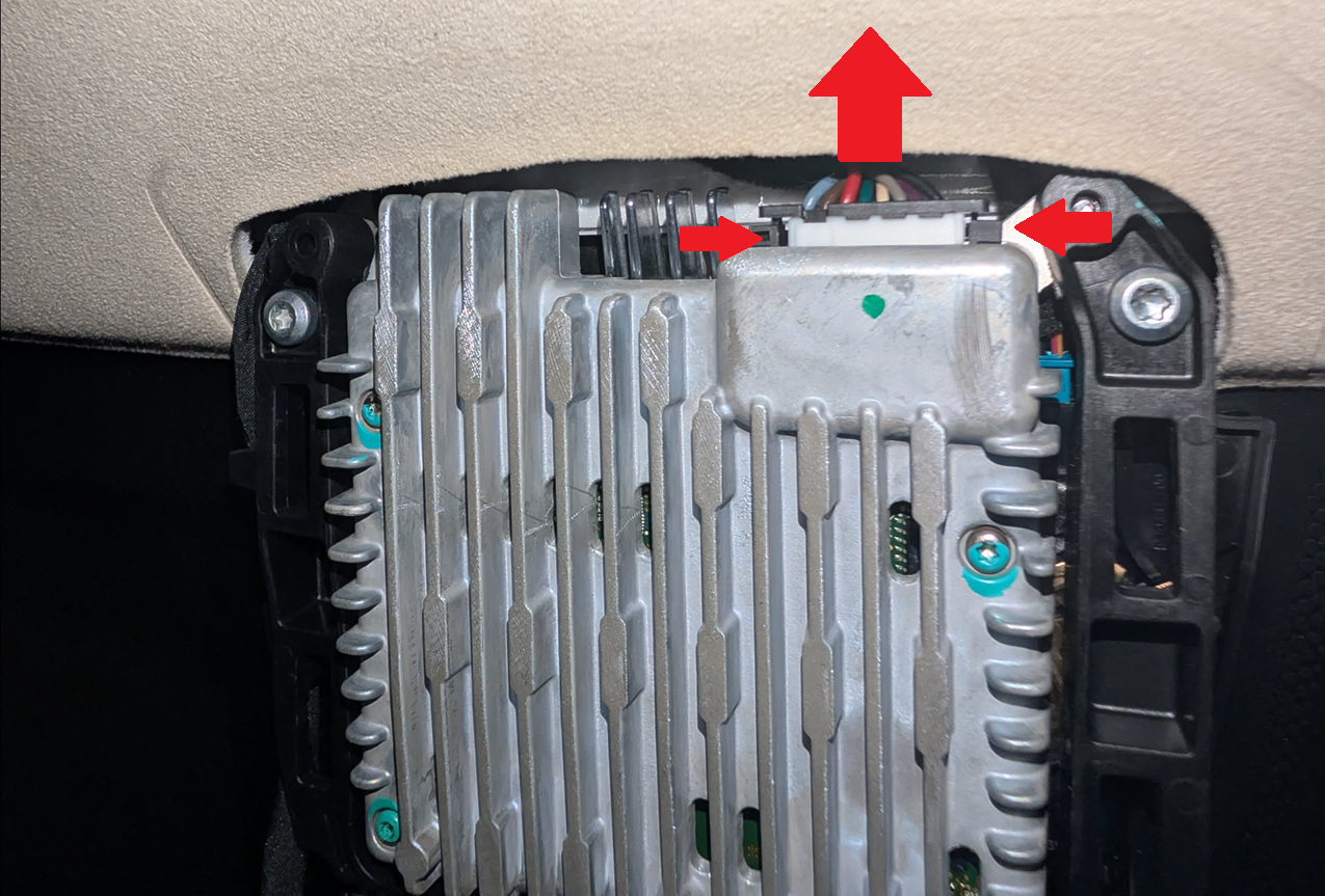
Remove the upper mirror headliner cover if you haven’t already. It’s held into place by two metal clips, pull straight down on the “back” side to detach it.
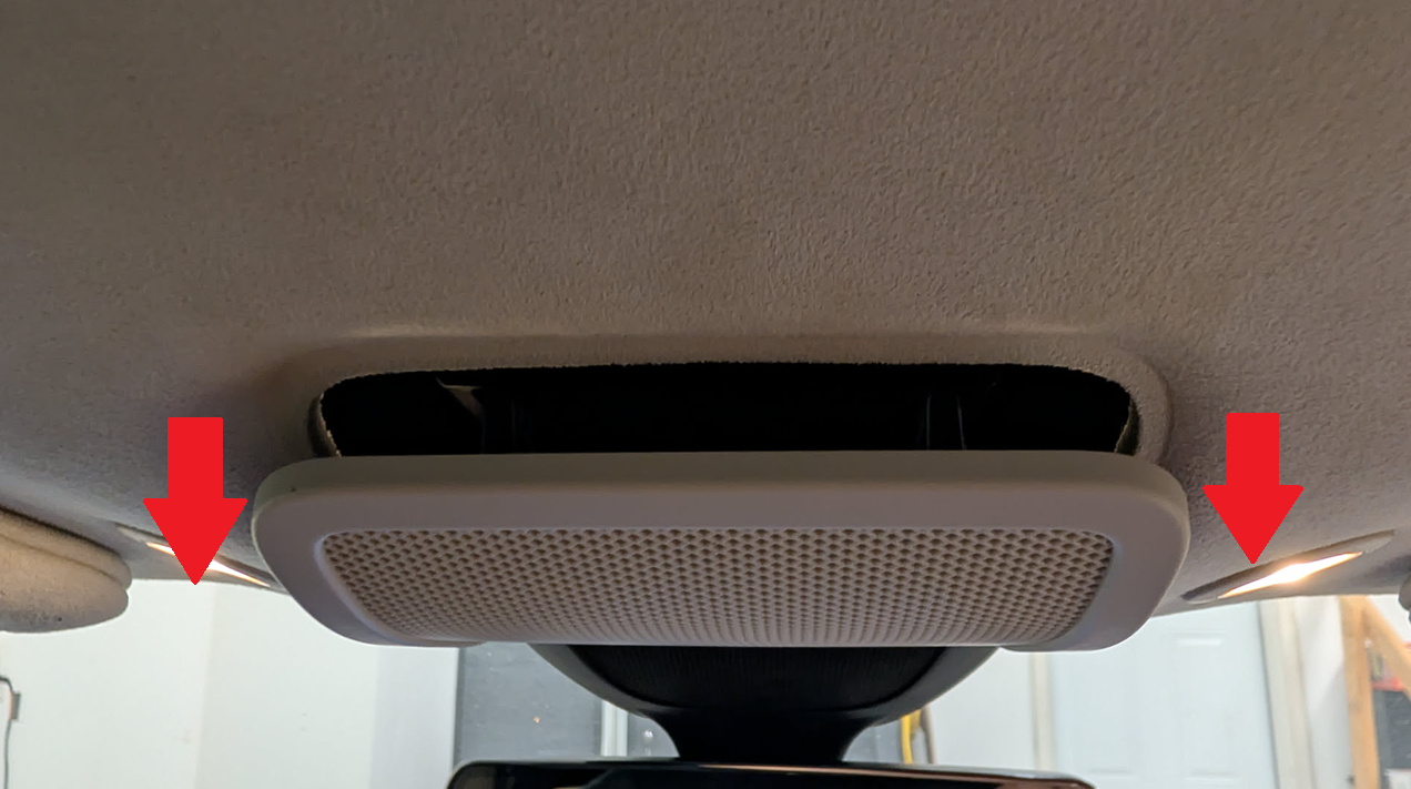
Pull the existing cable connected to the mirror assembly up through the headliner and route the one end of your harness back to the assembly and clip it into place (you should hear it click into place). Connect the other end of the harness to the cable that was previously connected to the mirror assembly. Then connect a USB-C cable to the developer harness box and route it down through the headliner.
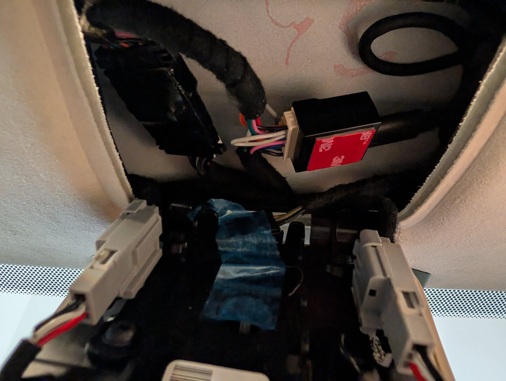
Looking up, I routed the USB-C cable from the Comma developer harness box around the mirror bracket and back into the headliner.
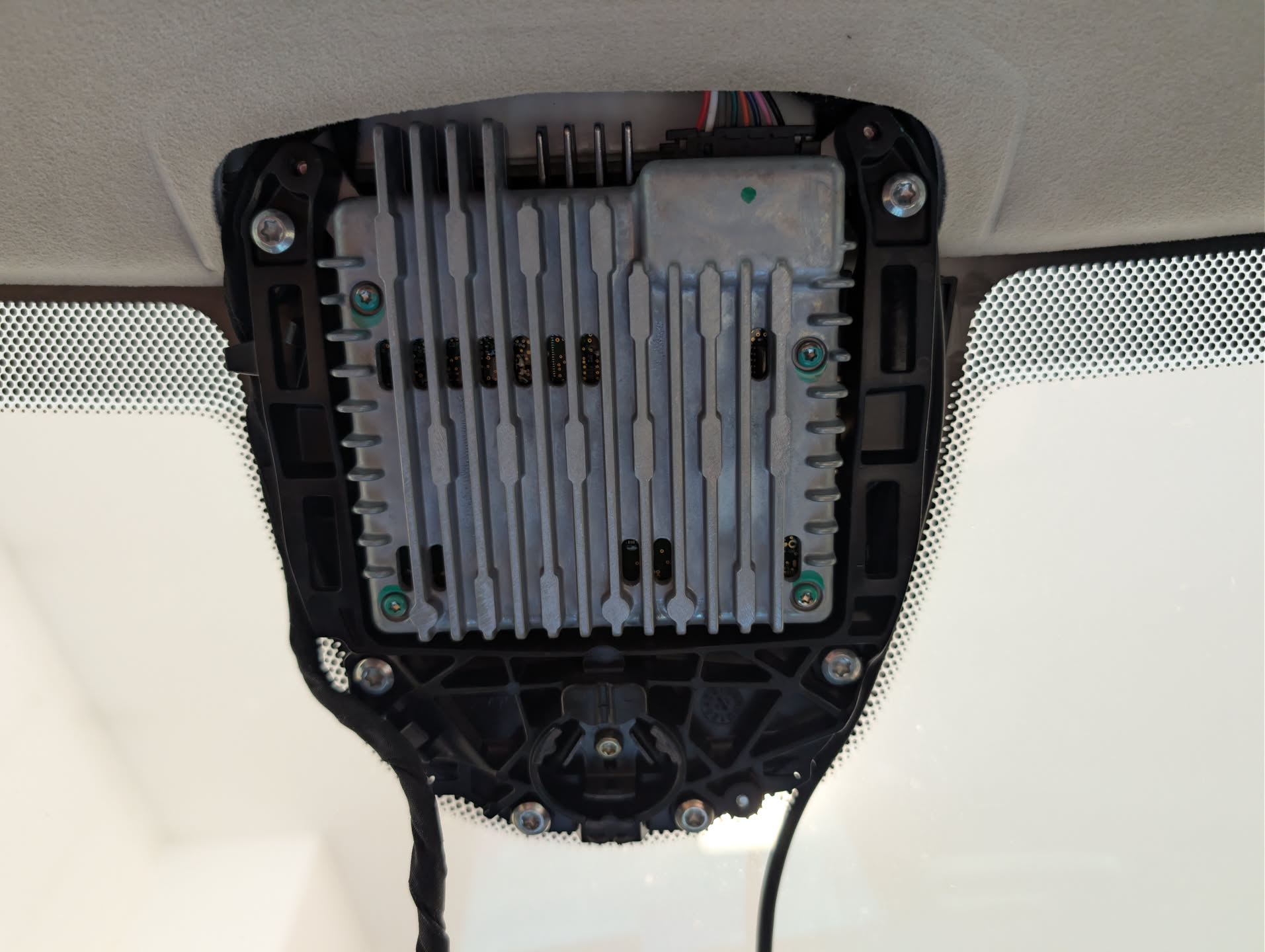
The top bracket should snap in place, even with the cable on the right side, with a tight fit.
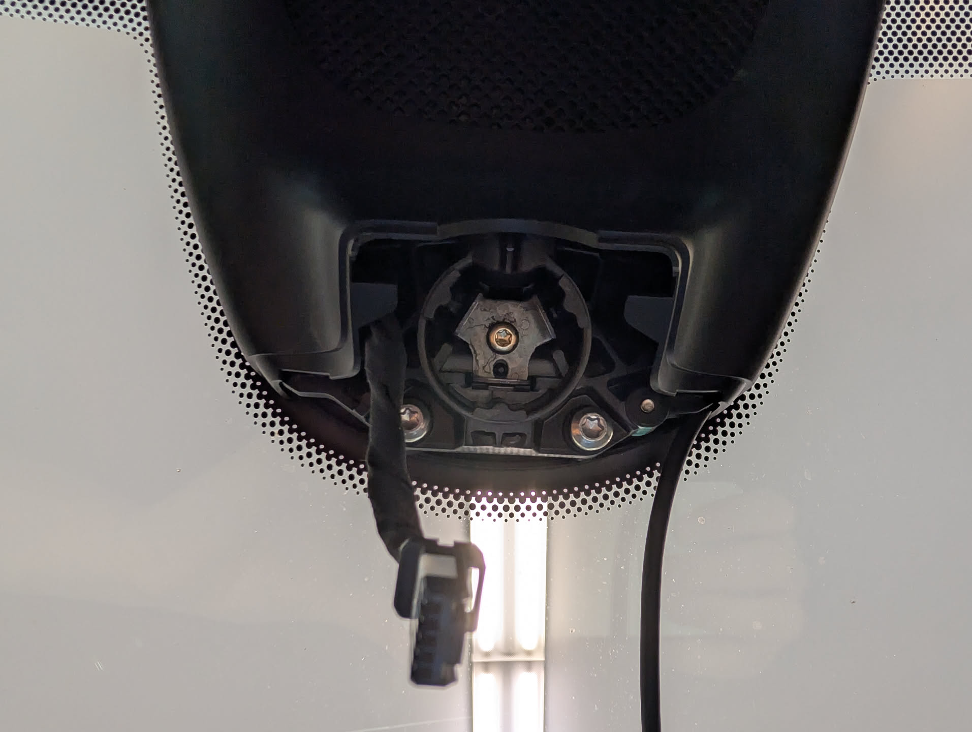
Snap the mirror into place first and then connect the wiring harness to it. Make sure the mirror is fully snapped into place; it can feel like it has, even though it hasn’t.
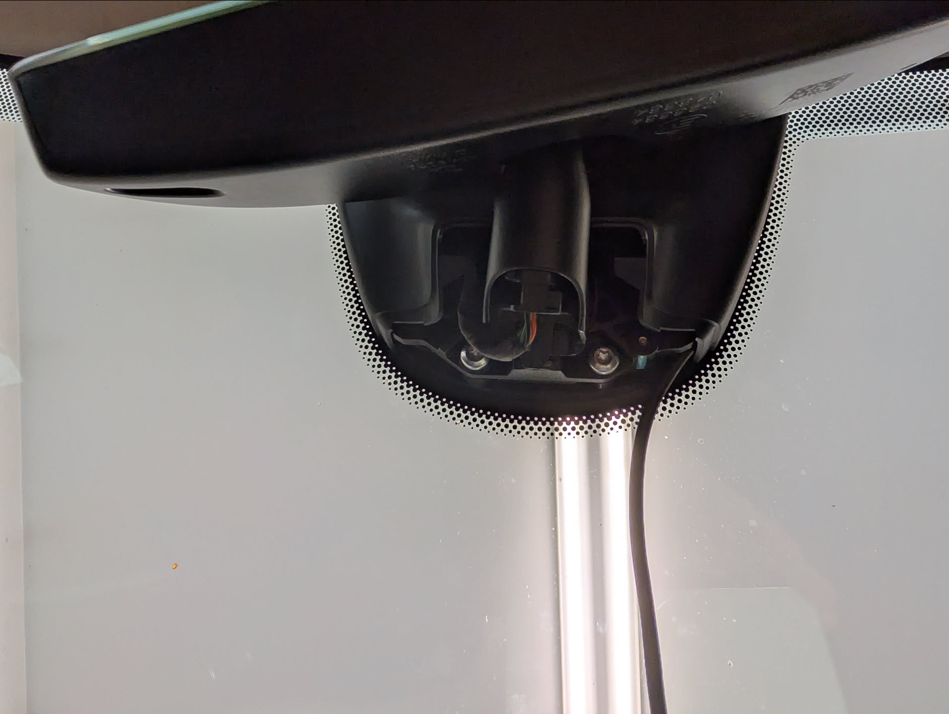
Mount your Comma 4 on the mount and connect the USB-C cable from the dev harness to the comma and it should immediately start to power up.

Install the xnor fork for the Comma 4

When the Comma 4 boots, you’ll land on a setup screen. Connect to WiFi (this is not optional as you need connectivity for the next step).

Eventually, the Comma will prompt if you want to use openpilot or Custom Software. Stock openpilot won’t do anything for you here as it doesn’t support older Tesla vehicles with AP1, so select custom software.

The fork that keeps AP1 alive is xnor, maintained by xnor-tech (Lukas Loetkolben on GitHub). Docs on how to get started can be found here: https://wiki.xnor.shop/docs/general/installing_a_fork/ On this step,

Enter this URL to install the xnor fork that has the Tesla AP1 car support: https://installer.comma.ai/xnor-tech/xnor

Unrelated, whoever at Comma was responsible for the onboard keyboard on the Comma 4 should get a gold star. The second I saw the keyboard I got anxiety that it would be miserable to type the URL in, but the keyboard honestly functions incredibly well for such a small screen. Kudos!

The install should take about 5-10 mins; it’s pretty quick.

    Notes:

    The `xnor` branch is the precompiled one and it covers comma four + comma 3X for Tesla Model S/3/X/Y across HW1 through HW4 — HW1 being what we care about for AP1.

    There’s also `xnor-dev` at `https://installer.comma.ai/xnor-tech/xnor-dev` which builds from source on the device. It takes considerably longer to install. Unless you have a reason to be on dev, take the precompiled branch.

    Setup Comma 4

    At this point, I ran through the rest of setup and calibration of the Comma 4.

    Ideally, you mounted the Comma 4 so you can run through the driver detection mode and pass it on first try. After driver monitoring, you’ll be prompted to run through device calibration, where you drive the car > 15 mph for a little bit of time.

    Unlike me, I mounted the Comma 4 blindly after tearing the mirror apart and one thing that later got me is the yaw of the device has to be within ±3.96°. Lucky me, I was off by 0.07 degrees at −4.03° and had to remount the whole thing. At time of writing this, Comma doesn’t have a mounting mode to show you want the yaw of the device is, so you kinda have best guess whether or not it’s level on the windshield. If it’s off, you’ll see a “Unable to calibrate” messages, with no details on what went wrong.

    If you unfortunately have to tear the Comma 4 mounting bracket off, I used a large wide razor blade that you use when scraping items or cleaning windows. Strongly recommend using that or some sort of plastic prying tool as trying to pull it off with your fingers is pretty much impossible

    In closing

    At this point, everything should be working. If it is, go ahead and repeat the mirror disassembly steps in reverse to reassemble it.

    This is a really brief guide and slightly scattered, but thought I’d post it as I couldn’t find what the mirror pins did and was curious if the original dev harness from Comma could be used as-is (which it looks like it can be! : )

    Disclaimer: At time of writing this article (and likely still not today), I am not affiliated with, sponsored by, or have any investment in comma ai or openpilot. I’m just some random person that wants to make my car feel like a car of the future again.

    Disclaimer 2: You are responsible for your own car and what you do with it. Follow local, state, and federal law when it comes to your vehicle and what you do with it.
    Configuring an MQTT broker for Home Assistant

    I recently purchased a ratgdo device to replace MyQ’s kit for a local non-cloud dependent solution. ratgdo offers homekit, mqtt, and Control4, Nice/Elan, or Crestron integration. For this tutorial, I’m going to cover ratgdo and MQTT integration.

    If you run Home Assistant as-is or are using their hardware, you can easily setup an MQTT broker by navigating to Add-Ons and installing the MQTT Broker, however in the past I have written articles on Home Assistant and Z-Wave JS as separate containers, so I wanted to follow the same concept by running the MQTT broker as a container as well.

    Across the board, the consensus seems to be that most people are running Mosquitto as an MQTT broker, so here is how you can get that setup as a container.

    1. Download the docker image for Mosquitto
    docker pull eclipse-mosquitto

    2. Create directories for Mosquitto’s config and data files. If desired, you can create one for logs as well, but I’m ok not persisting that.

    mkdir /home/docker/mosquitto/
    mkdir /home/docker/mosquitto/config
    mkdir /home/docker/mosquitto/data

    3. Create a configuration file for mosquitto. This file will configure what ports MQTT data should be listed on as well as its corresponding port for receiving data via WebSocket. In addition, we will define where data should be stored, and require authentication to be able to connect. For now, leave the password file, which contains the username/password combo for who can authenticate.

    vi /home/docker/mosquitto/config/mosquitto.conf

    Press i to enter insert mode and paste the following:

    listener 1883 0.0.0.0
    listener 9001 0.0.0.0
    protocol websockets
    persistence true
    persistence_file mosquitto.db
    persistence_location /mosquitto/data/
    allow_anonymous false
    #password_file /mosquitto/config/passwd

    Type !wq to save and quit.

    4. Start the mosquitto container. We’ll map both the mqtt and websocket ports and volumes for config and data to persist.

    docker run -d --restart=always --name="mosquitto-mqtt" -p 1883:1883 -p 9001:9001 -v /home/docker/mosquitto/config:/mosquitto/config -v /home/docker/mosquitto/data:/mosquitto/data eclipse-mosquitto

    5. Launch shell on the container

    docker exec -it -u 1883 mosquitto-mqtt sh

    6. Use the mosquitto_passwd utility to generate an encrypted username and password. An ask for the password will prompt once you run the command. Type exit to return back to your local terminal.

    mosquitto_passwd -c /mosquitto/config/passwd mqtt-user
    exit

    7. Modify your mosquitto.conf file.

    vi /home/docker/mosquitto/config/mosquitto.conf

    Uncomment the password file by removing the # sign and then type !wq to save and quit.

    8. Restart the container so mosquitto will pickup the username/password

    docker restart mosquitto-mqtt

    At this point, your mqtt broker service should be up and ready! If you’d like to test connectivity and authentication, download a copy of MQTT MQTT Explorer | An all-round MQTT client that provides a structured topic overview (mqtt-explorer.com)

    Set out of office / autoreply for distribution list for Exchange online

    One thing that is a bummer is Exchange online does not support setting an autoreply / out of office message for a distribution list. Usually if you want such functionality, you’d convert the distribution list to a shared mailbox and configure the autoreply or use a 3rd party utility, or potentially come up with some complex transform rule.

    Solution

    One workaround you can apply is to enable out of office / autoreply messages from recipients in the distribution list. By default, Exchange Online will suppress autoreply messages when going to a distribution list, but you can quickly configure the behavior to allow the messages per distribution list.

    Steps

    1. Install Exchange Online PowerShell module
      • Open PowerShell as an administrator and execute the following command:
        Install-Module exchangeonlinemanagement
    2. Import the module for use
      • Import-Module ExchangeOnlineManagement
    3. Login to Exchange online
    4. Configure the distribution list to allow the out of office / autoreply messages to be returned to the sender / originator.
      Set-DistributionGroup -identity [email protected] -SendOofMessageToOriginatorEnabled $true

    Result

    Now when someone emails the distribution list, they will receive an out of office / autoreply if configured by an individual member. Note, if multiple members have the autoreply configured, the sender/originator will receive multiple replies.

    How to generate a large files for testing

    You can generate large files for testing on both Linux and Windows machines without having to leverage a 3rd party utility.

    Windows

    In Windows, you can use the fsutil utility to create a new file with a defined number of bytes. In this case, the following command will generate a 1 GB file. The contents of the file will consist of spaces.

    fsutil file createnew "C:\Users\<username>\Desktop\sample.txt" 1073741824

    Linux

    In Linux, you can use the dd utility. In this case, this command will create a 1 GB file filled with 0s. The bs parameter is the block size and count is the number of blocks to create.

    dd if=/dev/zero of=testFile_dd bs=512M count=2

    Configuring DKIM for Postfix

    Fighting spam can be tricky. In addition to SPF records, DKIM is nearly mandatory to help prevent sent emails from being classified as spam. Beginning February of 2024, both Google and Yahoo will require DMARC, which require either SPF or DKIM; and in some cases for a high volume of emails (5,000+), both.

    In this tutorial, we will look at signed outbound messages with DKIM via use of the open source project OpenDKIM. If you followed my previous tutorial on Postfix + Dovecot + Mysql/MaraiDB, you may have multiple domain names, so this guide will assume you will want to configure separate DKIM keys for each domain name you are hosting.

    Step 1: Install OpenDKIM

    First, update packages for your distribution.

    sudo apt-get update && sudo apt-get upgrade

    Install OpenDKIM and OpenDKIM tools. OpenDKIM-tools has a utility to generate the keys we will use.

    sudo apt-get install opendkim opendkim-tools

    Step 2: Created trusted hosts configuration file for OpenDKIM

    First, create a file that OpenDKIM will use that defines the trusted hosts that can send messages.

    sudo mkdir /etc/opendkim
    sudo vi /etc/opendkim/TrustedHosts

    Add the IP addresses and fqdn of the server sending messages by typing i to change into insert mode in vi.

    127.0.0.1
    localhost
    192.168.1.2
    mail.mydomain.com

    Type :wq to commit the changes in vi.

    Step 3: Modify OpenDKIM configuration file

    Modify the opendkim.conf configuration file

    sudo vi /etc/opendkim.conf

    Search for #Canonicalization simple and uncomment the line by removing the # symbol.

    Search for #Mode and remove the # symbol to uncomment the line. Ensure the line is configured with s for signing outbound emails or sv for verifying dkim keys on sent and received emails.

    If you have subdomains, search for #SubDomains and remove the # and change to yes. For example:

    SubDomains              yes

    Search for Socket local:/var/run/opendkim/opendkim.sock and comment the line by adding a # in front of the line.

    Search for #Socket inet:8891t@localhost and uncomment the line. If the line does not exist in your document, then add the following at the end of your document.

    Socket inet:8891@localhost

    Next, add the following lines to reference our DKIM configurations for each domain:

    KeyTable /etc/opendkim/KeyTable
    SigningTable /etc/opendkim/SigningTable
    ExternalIgnoreList /etc/opendkim/TrustedHosts
    InternalHosts /etc/opendkim/TrustedHosts

    Type :wq to save the change and close the file

    Step 4: Configure Postfix

    sudo vi /etc/postfix/main.cf

    Add the following lines to the end of the file:

    milter_default_action = accept
    milter_protocol = 2
    smtpd_milters = inet:localhost:8891
    non_smtpd_milters = inet:localhost:8891

    Type :wq to save the changes and close the file.

    Step 5: Restart services to use the changes (optional)

    Execute the following to apply the changes if you wish to add domain names at a later time. If not, you can skip this step.

    sudo /etc/init.d/opendkim restart
    sudo /etc/init.d/postfix reload
    sudo /etc/init.d/postfix restart

    Step 5/6: Create a DKIM key for a domain

    Run the following command to create a new folder and change directory to it for where we will generate our key used to sign the outgoing emails.

    sudo mkdir -p /etc/opendkim/keys/mydomain.com
    cd /etc/opendkim/keys/mydomain.com

    Execute the following command to generate the key:

    sudo opendkim-genkey -r -d mydomain.com

    Delegate access to the opendkim user and group to access the key (note, if you modified the user in your opendkim.conf file, you will want to use that instead)

    sudo chown opendkim:opendkim default.private

    Step 7: Reference the key via OpenDKIM KeyTable

    Modify the Keytable with vi

    sudo vi /etc/opendkim/KeyTable

    Add the following line to the file to define your selector. In this example, we will call the selector default, but if your domain requires multiple DKIM keys, ensure you make this unique. You can modify the file by pressing i to enter insert mode in vi:

    default._domainkey.mydomain.com mydomain.com:default:/etc/opendkim/keys/mydomain.com/default.private

    Type :wq to write and quite vi

    Step 8: Specify the domain in your OpenDKIM SigningTable

    Open the SigningTable file via vi

    sudo vi /etc/opendkim/SigningTable

    Add the following line to the file by pressing i to enter insert mode (changing default if specified a different selector earlier on):

    mydomain.com default._domainkey.mydomain.com

    Type :wq to write and quite vi

    Step 8: Update your services to apply the changes

    Restart your services to begin signing your messages:

    sudo /etc/init.d/opendkim restart
    sudo /etc/init.d/postfix reload
    sudo /etc/init.d/postfix restart

    Step 9: Update DNS

    Get the DNS record values we need to publish by executing the following command:

    sudo cat /etc/opendkim/keys/mydomain.com/default.txt

    Create a new TXT record within your nameservers and specify the value between the quotes (don’t include the quotes). I.e.:

    v=DKIM1; h=sha256; k=rsa; s=email; p=ABCDEFG.....

    Note: I choose to update DNS last as once you update DNS, any servers that would receive mail before you apply the previous configuration may discard your emails. Then again, you didn’t have DKIM before, so you were probably going to junk mail anyways ;^)

    Credits

    Shoutout to Diego on stackoverflow, edoceo, and suenotek for consolidating a lot of these steps:
    postfix – Using DKIM in my server for multiple domains (websites) – Ask Ubuntu

    How To: Installing and Configuring OpenDKIM for multiple domains with Postfix on Linux | Edoceo

    Roundcube mail app and SPF, DKIM & DMARC on Ubuntu 20.04 (suenotek.com)

    How to generate a root certificate and create a self-signed server certificate issued from the root

    This is going to be a quick tutorial, but here’s a quick way to generate a root certificate, server certificate, and bundle them together via pfx file. This can be useful to validate scenarios where a certificate chain is required. For this tutorial, we’ll be using the openssl utility, which can be freely downloaded here: Win32/Win64 OpenSSL Installer for Windows – Shining Light Productions (slproweb.com)

    Generate the Root Certificate

    Execute the following command to generate a key for the root certificate:

    openssl ecparam -out root.key -name prime256v1 -genkey

    Execute the following command to generate a certificate signing request. Note: During this step, you will be prompted to specify several certificate attributes; for the common name, you can specify the name you’d like as the issuer (i.e. MyCorp)

    openssl req -new -sha256 -key root.key -out root.csr

    Execute the following to generate the public certificate. During this step, you’ll specify the validity of the root certificate (you may want this to be longer than 365 days as the root).

    openssl x509 -req -sha256 -days 3650 -in root.csr -signkey root.key -out root.crt

    Generate the Server Certificate

    Execute the following command to generate a private key for the server certificate:

    openssl ecparam -out server-cert.key -name prime256v1 -genkey

    Execute the following command to generate a certificate signing request. Note: During this step, you will be prompted to specify several certificate attributes; for the common name, specify the FQDN to your server. You do not need to start the value of the common name with CN=

    openssl req -new -sha256 -key server-cert.key -out server-cert.csr

    Execute the following command to generate the public certificate for the server certificate. During this step, you’ll specify the validity of the server certificate. Generally speaking, the validity of this certificate would be much shorter than your root.

    openssl x509 -req -in server-cert.csr -CA root.crt -CAkey root.key -CAcreateserial -out server-cert.crt -days 365 -sha256

    Verify certificate chain

    Optionally, you can verify the issuer or expiry dates of the server certificate is correct via the following command:

    openssl x509 -in server-cert.crt -text -noout

    Generate PFX from Root and Server certificate

    Execute the following command to generate a PFX file containing the public and private keys of the server certificate as well as public key of the root certificate. Note, you will be prompted for a password for the PFX file, which can increase security when needing to move these sensitive files around.

    openssl pkcs12 -export -out mycert.pfx -inkey server-cert.key -in server-cert.crt -certfile root.crt

    Using SDRplay RSPduo with RTLSDR-Airplay and a RaspberryPi

    One of the side projects I have is rebroadcasting local ATC (Air Traffic Control) audio from my local airport to LiveATC.net. I previously had an RTL-SDR dongle connected to a RaspberryPi 1 Model B, which then rebroadcasted to LiveATC via IceCast. While I’ve had success the past few years broadcasting, overhead plans were really the only thing that was clear; being distant from the airport, receiving broadcasts from the tower were a slim to none at best.

    In doing a bit of research I settled on purchasing a SDRplay RSPduo and Raspberry Pi 4, which seems to help with noise. Pairing the SDRplay with the newest version of RTLSDR-Airplay, I was able to achieve much clearer audio/hear things I couldn’t before. While I’m using the SDRplay RSPduo, this guide can be used for their other devices such as the Rsp1a and RSPdx as well (likely others as this guide ages). Here’s a reflection on how I got things setup.

    Update Raspbian packages

    First, update your Linux packages to latest version. I’m running the latest version of Raspbian / Debian.

    sudo apt-get update && sudo apt-get upgrade

    Disable WiFi/Bluetooth

    This is optional, but I figured I’d disable the radios on the RaspberryPi to further mitigate as much possible noise as possible. First, you can disable both radios by editing /boot/config.txt via the vi text editor (this can actually be configured by placing this file on your SD-Card you attach to your Raspberry Pi during first-time boot). Official details on the boot overlays can be found here.

    sudo vi /boot/config.txt

    Once in vi, press i to insert the following lines:

    dtoverlay=disable-bt
    dtoverlay=disable-wifi

    Press the escape key and then type :wq to write the changes to the file and exit vi.

    Lastly, execute the following command to disable the UART bluetooth service.

    sudo systemctl disable hciuart

    Download & Install RSP Control Library + Driver

    First, you will want to grab the latest SDRplay Drivers and Libraries. You can do this by navigating to SDRplay’s website and selecting RSPduo and ARM Raspberry Pi OS for the download. Then click the API button. Now this is kinda difficult if you are SSHed into the Pi, so I’d find the latest version from their website and then use the following commands below to remotely download the software (substituting in the version number to grab the latest download) and install it and reboot after install (rebooting after installation is strongly recommended).

    Execute the following commands:

    # Navigate to home directory
    cd ~
    # Download latest API Library + Driver
    wget https://www.sdrplay.com/software/SDRplay_RSP_API-Linux-3.15.2.run
    # Provide execution rights to install the software
    chmod a+x SDRplay_RSP_API-Linux-3.15.2.run
    # Run the installer
    sudo ./SDRplay_RSP_API-Linux-3.15.2.run
    # Reboot the machine
    sudo reboot now

    Build and install SoapySDR from source

    In this section, we need to install SoapySDR which is a vendor and platform neutral SDR support library. Essentially this means that instead of needing a bunch of developers to write integrations into all the different SDRs, other software can leverage these interfaces to skip worrying about device compatibility and focus on what the application needs to do. As we’ll see later, RTLSDR-Airband does exactly this to provide support for tons of different SDRs. Kudos to the PothosWare team for enabling developers all over the world to build all sorts of SDR projects!

    So, to get this installed, we need to clone the source code from their GitHub repo and compile the project. Official documentation on this process can be found on their wiki, but I’m going to try and simplify everything here.

    Since Raspberry Pi doesn’t come with Git, I am going to use wget and unzip to do this, but if you don’t mind installing Git, that’d be the easier way to “clone” down the latest source code from GitHub (make sure you replace versions where appropriate, at time of writing this, 0.8.1 is the latest version).

    # Install dependencies needed to build this project
    sudo apt-get install cmake g++ libpython-dev python-numpy swig
    # Make sure we are back in our home directory
    cd ~
    # Grab latest tarball from GitHub
    wget -O soapy-sdr-0.8.1.tar.gz https://github.com/pothosware/SoapySDR/archive/soapy-sdr-0.8.1.tar.gz
    # Extract the tarball (this is like unzipping a .zip on Windows)
    tar xvfz soapy-sdr-0.8.1.tar.gz
    
    # Change directories into the new SoapSDR folder
    cd SoapySDR-soapy-sdr-0.8.1
    
    # Make a new folder called build
    mkdir build
    
    # Change directories into the build folder
    cd build
    
    # Execute cmake build automation
    cmake ..
    
    # Make installer (-j4 parameter increases build threads to make compilation quicker)
    make -j4
    # Make the installer copy files to right locations
    sudo make install
    sudo ldconfig #needed on debian systems
    # Navigate back to home directory
    cd ~
    # Delete the SoapySDR folder since we are done with it
    sudo rm -R SoapySDR-soapy-sdr-0.8.1

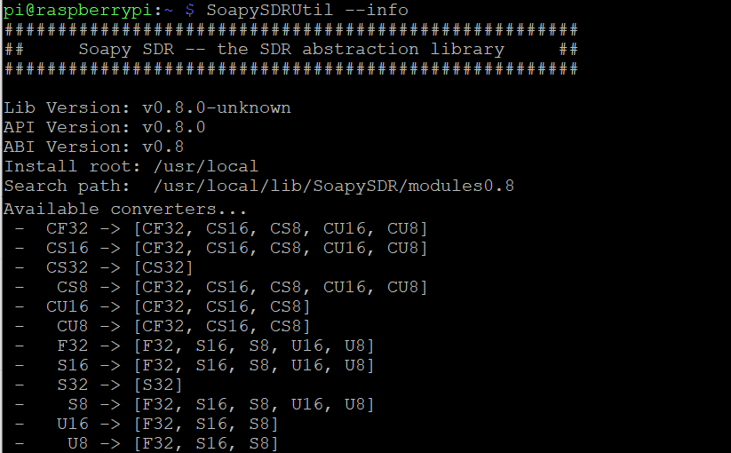
    At this point, you should be able to execute the SoapySDRUtil command and see the version you installed.

    SoapySDRUtil --info

    You should get something like this (note: you will likely see a missing module; that’s ok for right now!):

    Build and install SoapySDR Play module from source

    Now that we have SoapySDR installed, we need to install the module to allow it to control the SDRplay device. Similiar to SoapySDR install, we’ll pull down the latest files from the SoapySDR Play Module GitHub repo, build the installer, execute it, and verify that all went well. Official instructions can be found on their wiki as well.

    # Make sure we are back in our home directory
    cd ~
    # Grab latest tarball from GitHub
    wget -O SoapySDRPlay.zip https://github.com/pothosware/SoapySDRPlay3/archive/refs/heads/master.zip
    # Unzip the archive
    unzip SoapySDRPlay.zip
    # Change directories into the new SoapSDR folder
    cd SoapySDRPlay3-master
    # Make a new folder called build
    mkdir build
    # Change directories into the build folder
    cd build
    # Execute cmake build automation
    cmake ..
    # Make installer
    make
    # Make the installer copy files to right locations
    sudo make install
    sudo ldconfig #needed on debian systems
    # Navigate back to home directory
    cd ~
    # Delete the SoapySDR folder since we are done with it
    rm -R SoapySDRPlay3-master

    Plug in SDRplay RSPduo device and verify we see it

    If you haven’t already, go ahead and plug in your SDRplay RSPduo. Next, let’s verify we see it using the SopaySDRUtil command.

    SoapySDRUtil --probe="driver=sdrplay"

    You should see something like this and you should see your device and hardware version (note the hardware hardware= value as you may need that later). In addition, one thing that is neat about the RSPduo is there are multiple tuners/antennas. You will be able to see these values in the probe output. Once you enable RTLSDR-Airplay, you’ll notice active antennas are removed from the list of available devices.

    
    pi@raspberrypi:~ $ SoapySDRUtil --probe="driver=sdrplay"
    ######################################################
    ##     Soapy SDR -- the SDR abstraction library     ##
    ######################################################
    
    Probe device driver=sdrplay
    [INFO] devIdx: 0
    [INFO] hwVer: 3
    [INFO] rspDuoMode: 1
    [INFO] tuner: 1
    [INFO] rspDuoSampleFreq: 0.000000
    
    ----------------------------------------------------
    -- Device identification
    ----------------------------------------------------
      driver=SDRplay
      hardware=RSPduo
      sdrplay_api_api_version=3.070000
      sdrplay_api_hw_version=3
    
    ----------------------------------------------------
    -- Peripheral summary
    ----------------------------------------------------
      Channels: 1 Rx, 0 Tx
      Timestamps: NO
      Other Settings:
         * RF Gain Select - RF Gain Select
           [key=rfgain_sel, default=4, type=string, options=(0, 1, 2, 3, 4, 5, 6, 7, 8, 9)]
         * IQ Correction - IQ Correction Control
           [key=iqcorr_ctrl, default=true, type=bool]
         * AGC Setpoint - AGC Setpoint (dBfs)
           [key=agc_setpoint, default=-30, type=int, range=[-60, 0]]
         * ExtRef Enable - External Reference Control
           [key=extref_ctrl, default=true, type=bool]
         * BiasT Enable - BiasT Control
           [key=biasT_ctrl, default=true, type=bool]
         * RfNotch Enable - RF Notch Filter Control
           [key=rfnotch_ctrl, default=true, type=bool]
         * DabNotch Enable - DAB Notch Filter Control
           [key=dabnotch_ctrl, default=true, type=bool]
    
    ----------------------------------------------------
    -- RX Channel 0
    ----------------------------------------------------
      Full-duplex: NO
      Supports AGC: YES
      Stream formats: CS16, CF32
      Native format: CS16 [full-scale=32767]
      Antennas: Tuner 1 50 ohm, Tuner 1 Hi-Z, Tuner 2 50 ohm
      Corrections: DC removal
      Full gain range: [0, 48] dB
        IFGR gain range: [20, 59] dB
        RFGR gain range: [0, 9] dB
      Full freq range: [0.001, 2000] MHz
        RF freq range: [0.001, 2000] MHz
        CORR freq range:  MHz
      Sample rates: 0.0625, 0.096, 0.125, 0.192, 0.25, ..., 6, 7, 8, 9, 10 MSps
      Filter bandwidths: 0.2, 0.3, 0.6, 1.536, 5, 6, 7, 8 MHz

    Build and install RTLSDR-Airband from source

    RTLSDR-Airband is an open source project that allows you to receive analog radio voice channels and produce audio streams which can be routed to various outputs, such as online streaming via Icecast server, PulseAudio server, Audio file, or Raw I/Q file. In our case, we are going to stream to an Icecast server in this example.

    Similar to our previous section in SoapySDR, we need to download the latest source code, build and install RTLSDR, and then modify the configuration file. Official documentation can be found on the RTLSDR-Airplay GitHub Wiki.

    # Install RTLSDR-Airplay dependencies
    sudo apt-get install build-essential cmake pkg-config libmp3lame-dev libshout3-dev 'libconfig++-dev' libraspberrypi-dev libfftw3-dev
    # Navigate back to our home directory
    cd ~
    # Download the latest source from GitHub
    wget -O v5.1.1.tar.gz https://github.com/rtl-airband/RTLSDR-Airband/archive/refs/tags/v5.1.1.tar.gz
    # Extract the tarball
    tar xvfz v5.1.1.tar.gz
    # Change directory into the RTLSDR-Airband folder
    cd RTLSDR-Airband-5.1.1
    mkdir build
    cd build
    cmake ../
    make
    # Install the program
    sudo make install

    Configure RTLSDR-Airband

    For my particular setup, I want to stream to an external icecast server. To do that, I recommend creating a backup of the default configuration file (as a backup).

    # Rename the original config file as a backup
    sudo mv /usr/local/etc/rtl_airband.conf /usr/local/etc/rtl_airband.conf.bak
    

    Next, we can create a new configuration file with the proper configuration. Execute the following command to open vi.

    sudo vi /usr/local/etc/rtl_airband.conf

    Press i to go into insert mode and paste the following (replacing the values applicable to your environment; you may want to change the name of the stream, authentication parameters, and gain”). Also, note that we are using the first Antenna and specifying the hardware version of RSPduo from the previous step where we probed the SDRplay device (if you have a different SDRplay device, substitute that value accordingly).

    # Configure IceCast Stream
    devices:
    ({
      type = "soapysdr";
      index = 0;
      device_string = "driver=sdrplay,hardware=RSPduo";
      channel = 0;
      gain = 35;
      correction = 1;
      antenna = "Tuner 1 50 ohm";
      mode = "scan";
      channels: ( 
        {
          freqs = ( 133.8 );
          outputs: ( 
              {
                 type = "icecast";
                 server = "audio-in.myicecastserver.net";
                 port = 8010;
                 mountpoint = "station"
                 username = "username"
                 password = "mypassword";
                 name = "Tower";
                 description = "Tower - 133.8Mhz";
                 genre = "ATC";
              }
           );
        }
     );
    });

    Type :wq to write and save the changes to the file.

    Validate RTLSDR-Airband Configuration

    Once you have your configuration, you can validate everything is ready to go by running RTLSDR-Airplay in foreground mode.

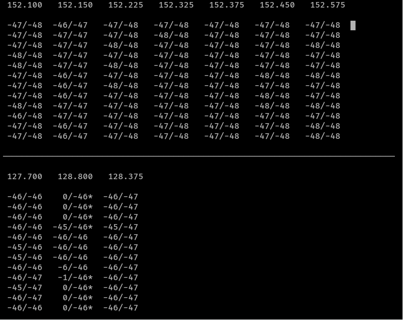
    From their wiki: you will see simple text waterfalls, one per each configured channel. This is an example for three devices running in multichannel mode. The meaning of the fields is as follows:

    User interface screenshot
    • The number at the top of each waterfall is the channel frequency. When running in scan mode, this will be the first one from the list of frequencies to scan.
    • The number before the forward slash is the current signal level
    • The number after the forward slash is the current noise level estimate.
    • If there is an asterisk * after the second number, it means the squelch is currently open.
    • If there is a > or < character after the second number, it means AFC has been configured and is currently correcting the frequency in the respective direction.

    Execute the following command to start running in foreground mode:

    # Test in foreground mode
    /usr/local/bin/rtl_airband -f

    Press Cntrl+C to break out of the stream once you are satisfied with your testing.

    Enable RTLSDR-Airband to autostart

    To enable RTLSDR-Airband to automatically start up each time your Raspberry Pi is rebooted, you can execute the following commands from within the RTLSDR-Airband directory.

    sudo cp init.d/rtl_airband.service /etc/systemd/system
    sudo chown root:root /etc/systemd/system/rtl_airband.service
    sudo systemctl daemon-reload
    sudo systemctl enable rtl_airband
    sudo systemctl start rtl_airband

    Hurray! We are done!

    If you made it this far you have completed all the steps! Enjoy your new streaming SDR solution!

    Controlling a Haiku fan with a wall switch

    TLDR: I wanted to control the light on Big Ass Fans’ Haiku fan via physical wall switch, so this tutorial is going to go over how to pair a smart switch with Home Assistant software to provide a traditional light switch experience. Skip down to Setting up the wall switch to start if you want to skip my ramblings.

    Here’s a YouTube video if you don’t like to read:

    Longer story

    In the background of many commercial buildings, silently lurking and judging us from above, lies what looks like possibly a recycled helicopter blade. Don’t be fooled, these blades are no helicopter blade, they are years of engineered excellence in the makings. The company prides themselves on solid engineering and building a solid product for their customers. They are called Big Ass Fans.

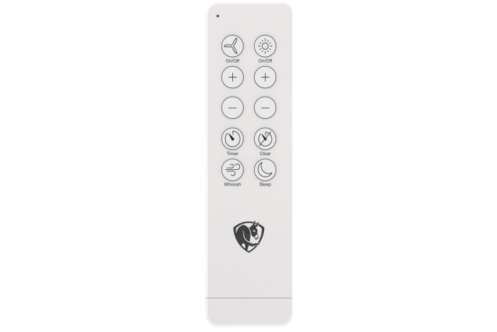
    For quite some time I’ve been eyeing their Haiku fan, which is their residential ceiling fan. Their fans look incredibly modern, operate almost completely silent, have a “SenseMe” feature that figures out when people are in the room to automatically do stuff, and they have an API that you can integrate into locally on the fan via WiFi (lose internet, no problem, you can still control your fan!). One of my biggest “beefs” with today’s companies is they try to make things really proprietary and crappy, so seeing the company that takes pride in their product and allowing others to integrate into it remotely without internet is super “cool” 😉

    You spin me right round

    The fan itself is smart… too smart

    One thing that’s really interesting, is when you hook up the fan, to me, it’s designed more like their commercial units where it needs to be constantly powered on; from there you remotely control the fan either by remote or their smart phone application. Both the remote and even the mobile app, work incredibly well and are extremely responsive, but the only tricky thing about the fan is in a residential setting, many folks have light/fan combos in their bedrooms, offices, and living rooms and if a guest walks into the room and flips the light switch, they are flipping power to the whole fan/light.

    So….?

    In many commercial settings, fans you typically set once and let em’ rip, but with the residential play, you have grandparents, guests, friends, etc. that may come over. Since the remote is there, they go, how do I turn the lights on to this room? Unfortunately, there isn’t a good answer here other than to put a plate on the wall and force your guests to check out the remote.

    I personally find the remote a hassle since I have a small little corridor into one room, so when it’s darker in the evenings, you grab the remote on the wall, walk through this dark area, and then aim the remote somewhere at the ceiling to turn it on (this is if you don’t forget the remote in the room from before).

    So…?

    I am a “big fan” of having a smart home, but I want it to be super intuitive to the end user. I design everything to be used as if my grandparent is over and they have no idea what the heck is going on. In this case, I leveraged an open source project called Home Assistant and a Leviton Z-Wave switch to do the magic of controlling the fan like any other fan you’d buy at a big box store. More specifically, I really just needed to control the light on the fan, so this tutorial is going to go over how to control the light from the fan via the switch.

    Setting up the wall switch

    The first thing you’ll need is a smart switch. It can be WiFi, Z-Wave, ZigBee, etc; it doesn’t matter specifically what brand (odds are, it’ll be compatible (here’s the official list)), but you’ll need a switch that allows you to control it via the computer or your phone. I used a dimmer switch specifically as the light on the Haiku allows several different levels of brightness.

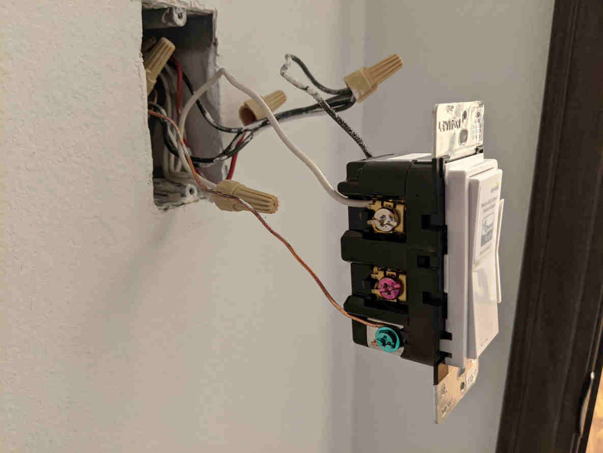
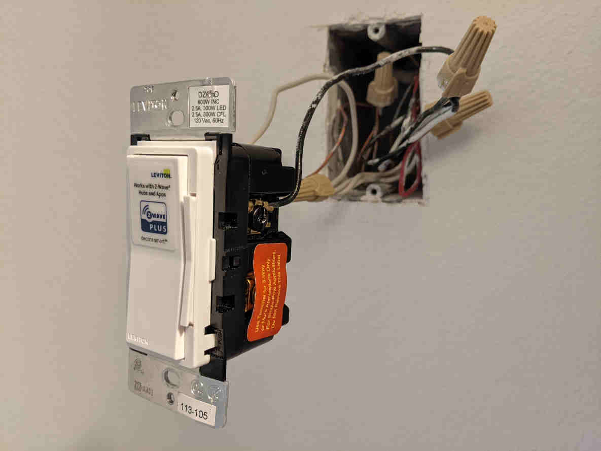
    Once you have the switch, what you’ll want to do is wire up the fan so it constantly has power and also give power the switch. This does two things: 1) it allows the fan to be powered on regardless if your guest turns the light switch on/off 2) it allows the light switch to stay powered on so you use that to talk to your fan. Here’s an example of how I wired my Leviton Z-Wave switch.

    Here you can see I don’t have anything connected to the red pin, or load. Typically, you’d have this connect back to the fans lights to turn them on/off, but the Haiku fan isn’t wired like that.

    On this side, you can see we only have the negative wire connected. It’s hard to see, but in the box, I have all my neutral and negative wires capped together, which offers power to the fan 100% of the time, regardless of what this switch is doing.

    Once you have the switch wired up and ready to go, it should literally do nothing when you turn it on/off, but your fan should stay on all the time.

    Setting up Home Assistant Automation

    This guide won’t go into installing / setting up Home Assistant, rather more so around the automation scripts needed to get this all working. If you are interested in learning more about Home Assistant, you can check out their website here and I have a blog post on how to deploy Home Assistant on a Raspberry Pi here.

    To get this working, you will need a couple of things:

    • Add your smart switch to Home Assistant
    • Install HACS
    • Install Haiku SenseMe Integration
    • Add two automation scripts
      • One to control light on/off events
      • One to control light brightness events
    Add your smart switch

    I won’t go into details here too much since every switch will have a separate way to install (Z-Wave vs WiFi vs Zigbee for example), but here is a nice YouTube video on how to get things going (https://youtu.be/FtWFSuMdiSQ?t=353).

    HACS

    If you have used Home Assistant, it comes with many different native integrations out of the box. Unfortunately, many integrations are developed so quickly the HA (Home Assistant) team doesn’t have time to vet them all, so they end up being maintained by the community. HACS helps install these integrations, so I’d recommend installing this.

    Step-by-Step documentation on installation can be found here: Prerequisites | HACS

    Haiku Integration

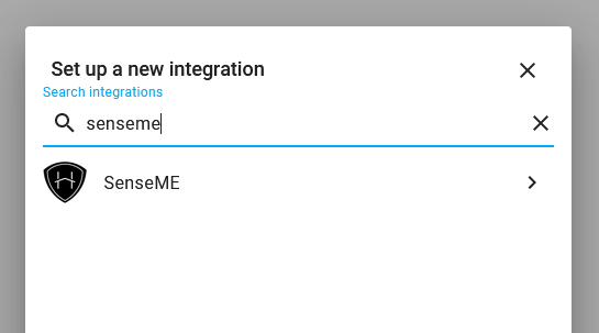
    A few much smarter folks wrote up an integration for the Haiku fan called SenseME, which we need to install. Once HACS is installed, you can search for the integration via HACS and install the integration. Copied from their integration, here is how to install the integration:

    1. Go to Configuration -> Integrations.
    2. Click on the + ADD INTEGRATION button in the bottom right corner.
    3. Search for and select the SenseME integration.
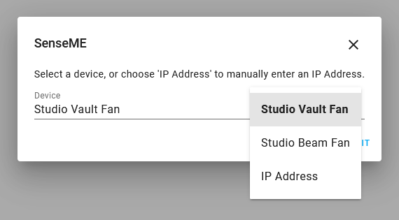
    4. If any devices are discovered you will see the dialog below. Select a discovered device and click Submit and you are done. If you would prefer to add a device by IP address select that option, click Submit, and you will be presented with the dialog in step 5.
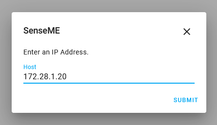
    5. If no devices were discovered or you selected the IP Address option the dialog below is presented. Here you can type in an IP address of undiscoverable devices.
    6. Repeat these steps for each device you wish to add.

    Information on the SenseME integration can be found on their GitHub site here: mikelawrence/senseme-hacs: Haiku with SenseME fan integration for Home Assistant (github.com)

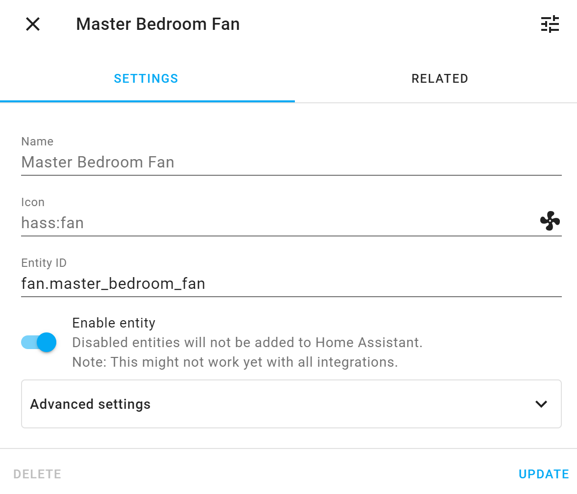
    Once configuration is completed, you should see an entity for your fan listed that looks something like this.

    On/Off Automation

    This automation will first control On/Off behavior from your light switch.

    1. Go to Configuration -> Automations.
    2. Click on the + ADD Automation button in the bottom right corner.
    3. Click the START WITH AN EMPTY AUTOMATION button
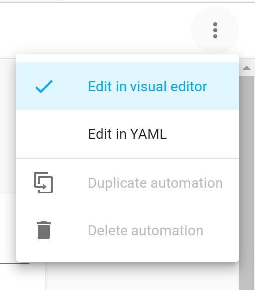
    4. Click on the three dots in the top right corner and click Edit in YAML

    5. Paste the following code; make sure you edit the names of each of your light switch entities (one for your fan light and one for the light switch on the wall):
    light.your_light (the light for your wall) and light.fan_light (the light on the Haiku fan).

    alias: Turn On/Off Haiku Fan/Wall Switch
    description: ''
    trigger:
      - platform: state
        entity_id: light.your_light, light.fan_light
        from: 'off'
        to: 'on'
      - platform: state
        from: 'on'
        to: 'off'
        entity_id: light.your_light, light.fan_light
    condition: []
    action:
      - service: light.turn_{{ trigger.to_state.state }}
        data:
          entity_id: |-
            {% if trigger.entity_id == 'light.your_light' %}
              light.fan_light
            {% elif trigger.entity_id == 'light.fan_light' %}
              light.your_light
            {% endif %}
    mode: single

    6. Click the SAVE button

    Brightness Automation

    This automation will first control On/Off behavior from your light switch.

    1. Go to Configuration -> Automations.
    2. Click on the + ADD Automation button in the bottom right corner.
    3. Click the START WITH AN EMPTY AUTOMATION button
    4. Click on the three dots in the top right corner and click Edit in YAML
    5. Paste the following code; make sure you edit the names of each of your light switch entities (one for your fan light and one for the light switch on the wall):
      light.your_light (the light for your wall) and light.fan_light (the light on the Haiku fan).
    alias: Sync Haiku Fan/Wall Switch Brightness
    description: ''
    trigger:
      - platform: state
        entity_id: light.your_light, light.fan_light
        attribute: brightness
        for: '00:00:02'
    condition:
      - condition: template
        value_template: '{{ trigger.to_state.attributes.brightness > 0}}'
    action:
      - service: light.turn_on
        data:
          brightness: '{{ trigger.to_state.attributes.brightness }}'
          entity_id: |-
            {% if trigger.entity_id == 'light.your_light' %}
              light.fan_light
            {% elif trigger.entity_id == 'light.fan_light' %}
              light.your_light
            {% endif %}
    mode: restart

    6. Click the SAVE button

    Testing!

    At this point, whether you use your remote or the light switch, your lights should be in sync! Use the remote or the wall switch to the turn on/off the lights. Try using the switch to dim and it should adjust the brightness of the light (note: there may be a tiny delay after you make changes to the dimmer value as there’s a 2second delay in the automation, which prevents the lights from going wonky).

    Conclusion

    Through the use of Home Assistant + any smart switch, we can easily control the Haiku fan with physical nobs and dials. While this tutorial only covers controlling the fan’s light via a switch, the same principals can be used to add a second switch to control the fan speed.

    For those that like physical knobs and dials to control your devices, hope this was helpful!

    If you are thinking of buying a Big Ass Fan, please consider using my referral code so I can use them towards future reviews! https://bigassfans.referralrock.com/l/1JACKSTROMB57/

    [Tutorial] How to create a bootable USB Drive to flash a Lenovo device’s BIOS

    This tutorial will review how to create a bootable USB drive to flash the fimrware/bios on your Lenovo device.

    Before we begin, Lenovo offers three different downloads for Firmware today:

    1. Windows installer/flash utility (.exe)
    2. CD ISO version (.iso) to burn to a disk
    3. USB Flash Package (.zip)

    While the USB Flash Package (.zip) is exactly what we are looking for, by default if you just drag the files onto your USB drive, it won’t boot to the flash utility. In this case, the instructions below will show you have to make the drive bootable and then launch the USB Flash Package.

    Make a bootable drive

    First, you will want to download a copy of the Rufus utility. This utility is an open source utility for Windows only, but will allow you to make a bootable USB drive. You can obtain a copy of the utility here. Rufus’ website can officially be found here: https://rufus.ie/

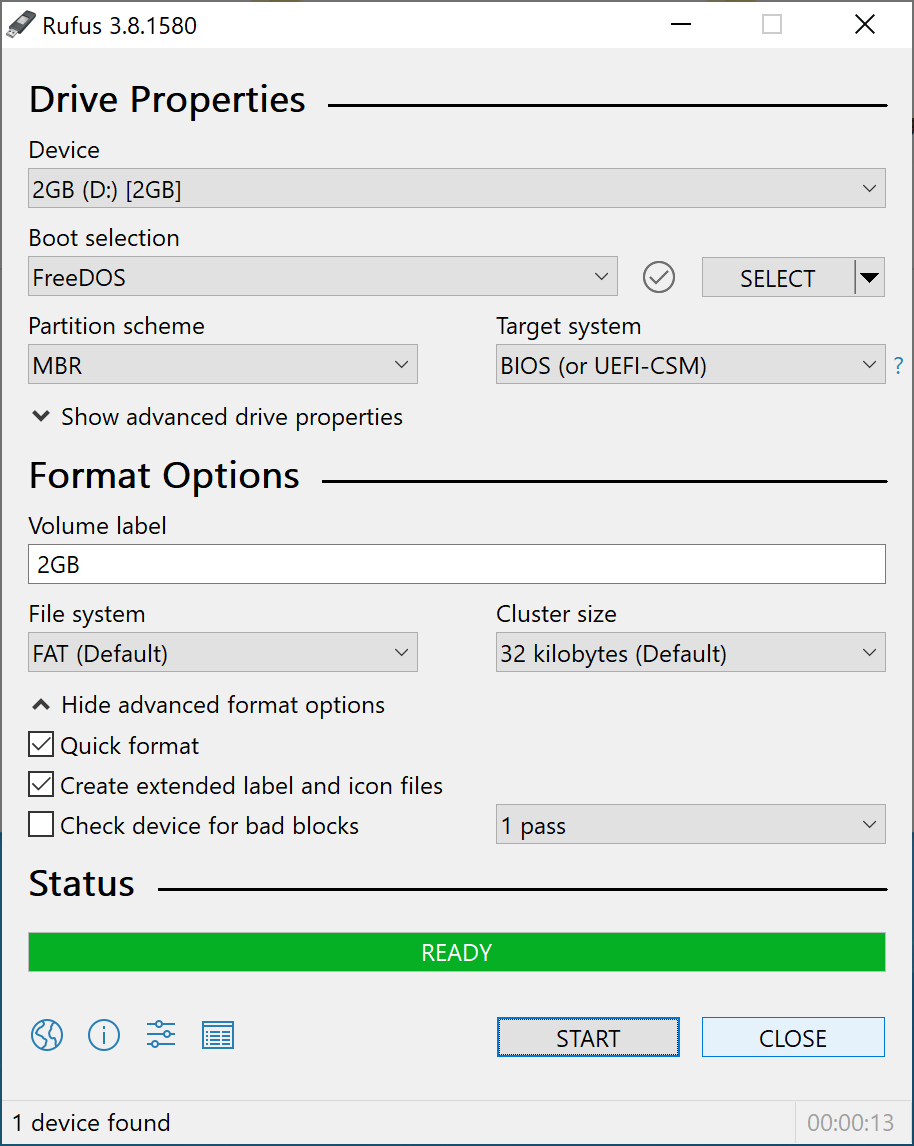
    Once installed, open the application. Select your USB device you wish to flash (note this will erase all data on your device) and set the Boot selection to FreeDOS. Once your Device and Boot selection has been set, go ahead and click Start to flash the device.

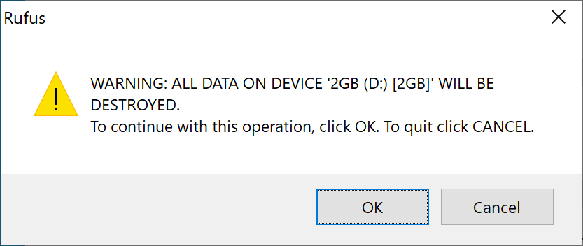
    You will be prompted to confirm you are OK with erasing the device. Go ahead and click OK if you are sure you have selected the correct device in the prior step.

    Once completed, you should see a green bar that says READY. This is kinda misleading, wish it would say completed, but your device should be flashed at this point.

    Download the right firmware from Lenovo

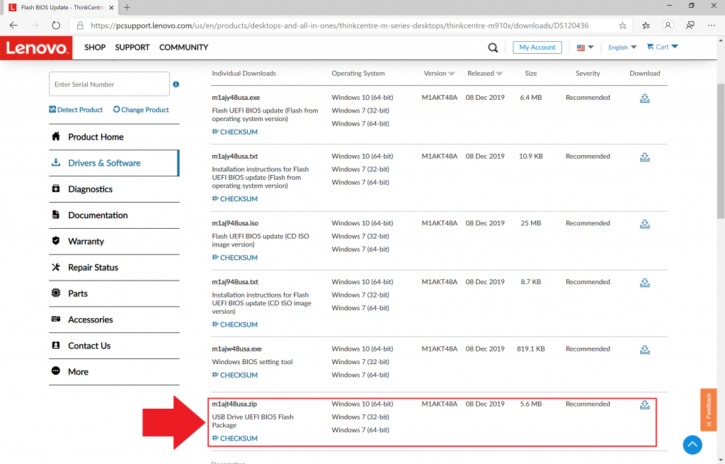
    As mentioned earlier, Lenovo offers 3 different types of downloads on their website. You will want a copy of the zipped installer as shown in the screenshot below.

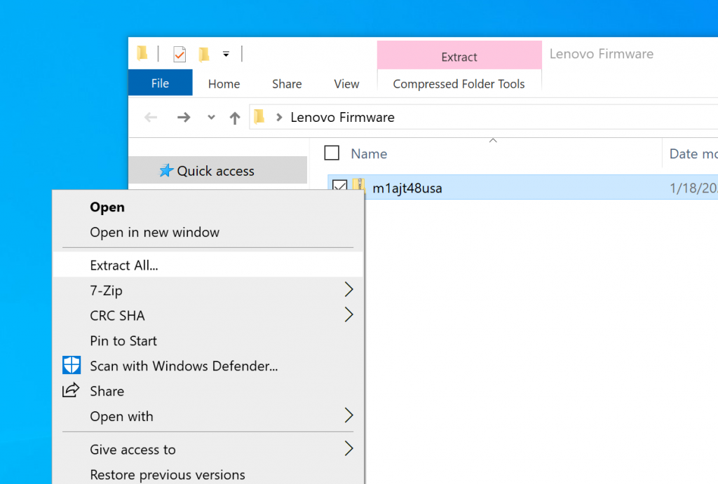
    Once downloaded, navigate to where you downloaded the zipped file, right click, and select Extract All… If you don’t see Extract All… then try downloading a copy of 7-Zip, which is a fantastic free archiver solution that can open all types of compressed files (zip, 7zip, tar.gz, etc)

    In this picture, we show right clicking the zipped folder and clicking Extract All… on the file.
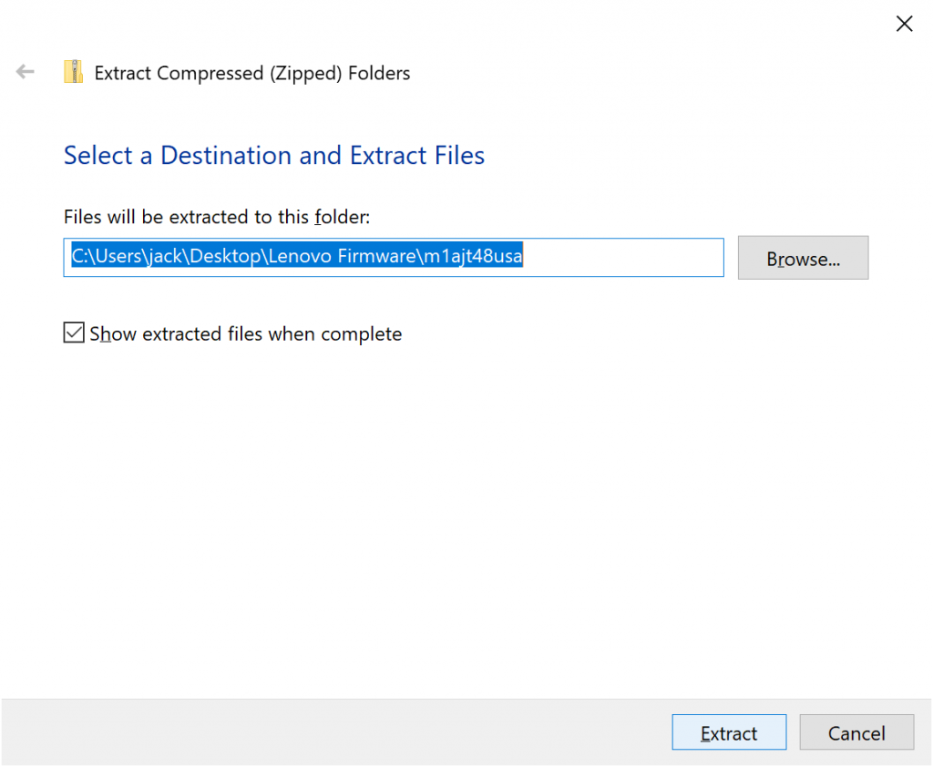
    In this picture, we are selecting the folder to where the extracted files should go.

    Copy the extracted files to your bootable USB drive

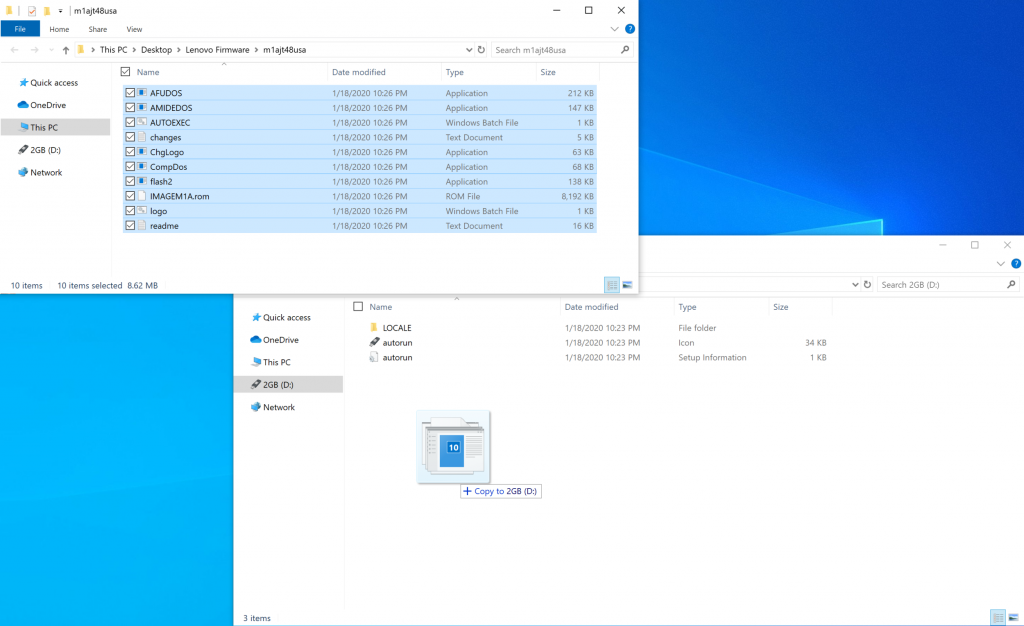
    Once you have extracted the files from the zipped folder from Lenovo, you will want to copy and paste the files from the extracted directory to the bootable USB drive. To show visually, I opened two file explorer windows, one in the directory of the extracted firmware and the other on the bootable USB drive. I simply dragged and dropped the files from the firmware directory to the bootable USB drive.

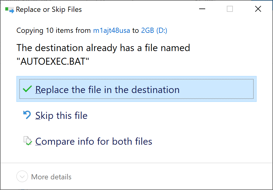
    When you try to copy the files from the firmware directory to the bootable USB drive, you will be prompted to replace AUTOEXEC.BAT. Make sure to Replace the file in the destination as this will execute the command to launch the flash2 utility, which actually writes the firmware to the device.

    Plug in the drive and set the device to boot to it

    At this point, you should have a bootable USB device that you can now plugin to your Lenovo device. You can unplug it from your client machine and plug it in to your Lenovo device. Make sure you set your Lenovo device to boot from the USB drive (this can usually be set by pressing the F1 or F2 keys during the post screen).

    What to expect

    Upon boot, you should be greeted by the Lenovo flash utility, which will ask if you want to update your device. Please note, that in my experience, once I select yes the device needed to reboot several times and may boot into the BIOS. The utility will tell you when everything is completed, so make sure you don’t power down your device or unplug your USB drive after the first or second reboot, make sure you wait things out. As with updating any firmware, make sure you don’t do this in a storm or on a device with low battery as you ensuring little chance of disruption as possible is absolutely critical.

    Summary

    At this point, you should have a bootable USB drive created by Rufus and FreeDOS that can be paired with Lenovo’s firmware to go around and flash your devices. Hope this helps!

    DPM 2016 – Reporting Services Server cannot connect to DPM Database

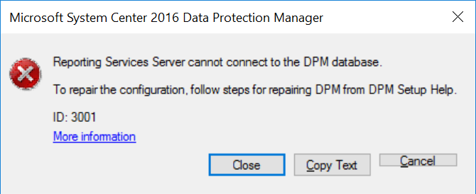
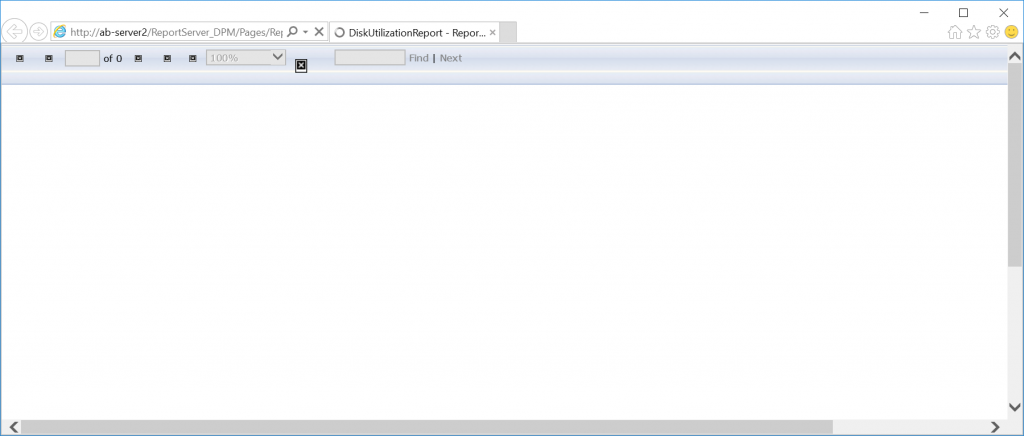
    After installing System Center Data Protection Manager from scratch or after performing an upgrade from DPM 2012 R2, when you attempt to schedule a report to be mailed, you receive the following popup error or notice that when you generate a report you just receive a white page in your browser that continues to load indefinitely:


    Reporting Services Server cannot connect to the DPM database.
    To repair the configuration, follow steps for repairing DPM from DPM Setup Help.
    ID: 3001
    More Information
    Just an endless loading page presented in your browser.

    Unfortunately, following the repair steps suggested in the More Information link does not resolve the problem.

    Resolution for SQL Server 2016 and later

    1. On the DPM server, open Computer Management, expand Local Users and Groups, click Groups, and create a new local group with the following information (replace items in red with the actual server name/hostname of your machine):
      1. Group name: DPMDBReaders$DPMSERVERNAME
      2. Description: This group is internally used by Microsoft System Center 2016 Data Protection Manager.
    2. On the DPM server, open Computer Management, expand Local Users and Groups, click Users, and create a new local user with the following information (replace items in red with the actual server name/hostname of your machine):
      1. User name: DPMR$DPMSERVERNAME
      2. Full name: DPMR$DPMSERVERNAME
      3. Description: This account is used for SQL reporting to generate reports for DPM 2016.
      4. Enter a strong password
      5. Check Password never expires
    3. Select your recently created DPMR$DPMSERVERNAME account and click on the Membership of tab
      1. Add the DPMDBReaders$DPMSERVERNAME group we created in step 1
      2. Click OK
    4. Start Microsoft SQL Server Management Studio and connect to the SQL instance used by DPM.
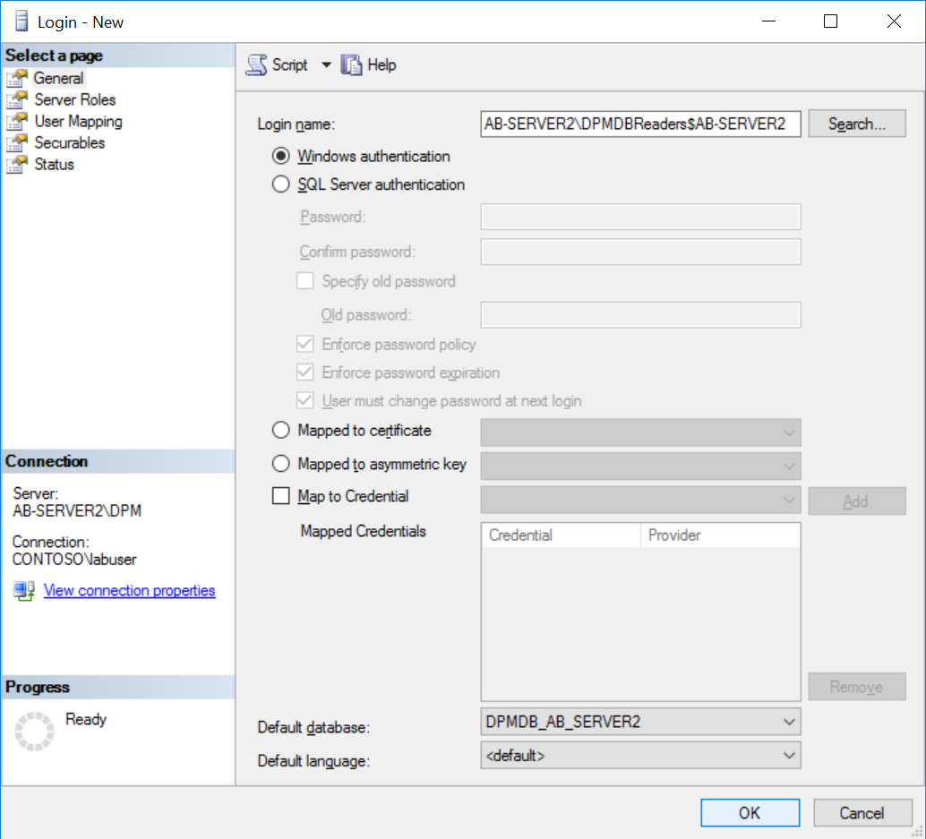
      1. Expand Security, right-click on the Logins, select New login
        1. Click on the Search… button and add the local group DPMDBReaders$DPMSERVERNAME
        2. Set the Default database to YourDPMDatabase

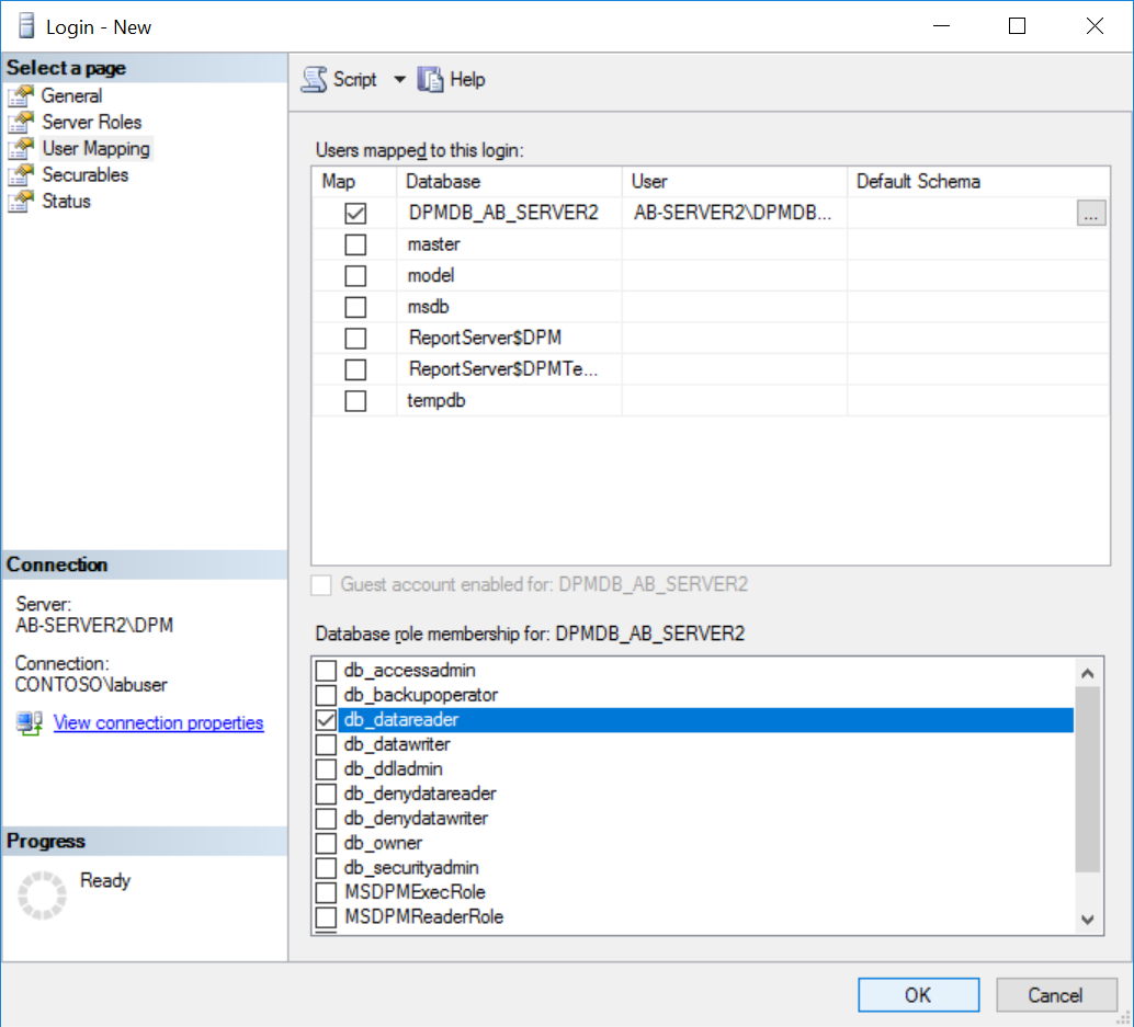
        3. Click on the User Mapping section, check the checkbox for YourDPMDatabase, and check the checkbox for the db_datareader role.
        4. Click OK
    5. In Microsoft SQL Server Management Studio, expand Databases, expand YourDPMDatabase, expand Security, expand Users, and right click Properties on the DPMDBReaders$DPMSERVERNAME group you granted access to in step 4.
      1. Click on Securables
      2. Click the Search… button
      3. Select Specific objects… and click OK
      4. Click the Object Types… button
      5. Check Stored precedures and click OK
      6. Click the Browse… button
      7. Check [dbo].[prc_MOM_Heartbeat_Get] and [dbo].[prc_MOM_ProductionServerGet] and click OK
      8. Click OK on the Select objects dialog box
      9. Place a checkbox in the Grant column for the Execute row.
        1. Make sure you do this step for both [dbo].[prc_MOM_Heartbeat_Get] and [dbo].[prc_MOM_ProductionServerGet], checking the box once will only update one of the storage procedures.
      10. Click OK
    6. Exit Microsoft SQL Server Management Studio.
    7. Open Reporting Services Configuration Manager and connect to the SqlServer and Instance hosting the DPM reports (as you go through this, replace the items in Red with your applicable values).
      1. Click on the Web Portal URL menu item and click on the listed URL for DPM.
      2. Click on the DPMReports_GUID folder to open the DPM reports page.
      3. Click on the DPMReporterDataSource Data Source to open its properties.
      4. Under Credentials, use the following configuration:
        1. Select the Using the following credentials radio button
        2. Type of credentials: Windows user name and password
        3. User name: DPMR$DPMSERVERNAME
        4. Password: EnterYourPasswordToTheAccount
        5. Ensure Log in using these credentials, but then try to impersonate the user viewing the report is unchecked
        6. Click the Test connection button
          1. Ensure it says Connected successfully

        7. Click Apply
      5. Close out of your web browser
    8. Back in the Reporting Services Configuration Manager window, complete the following steps
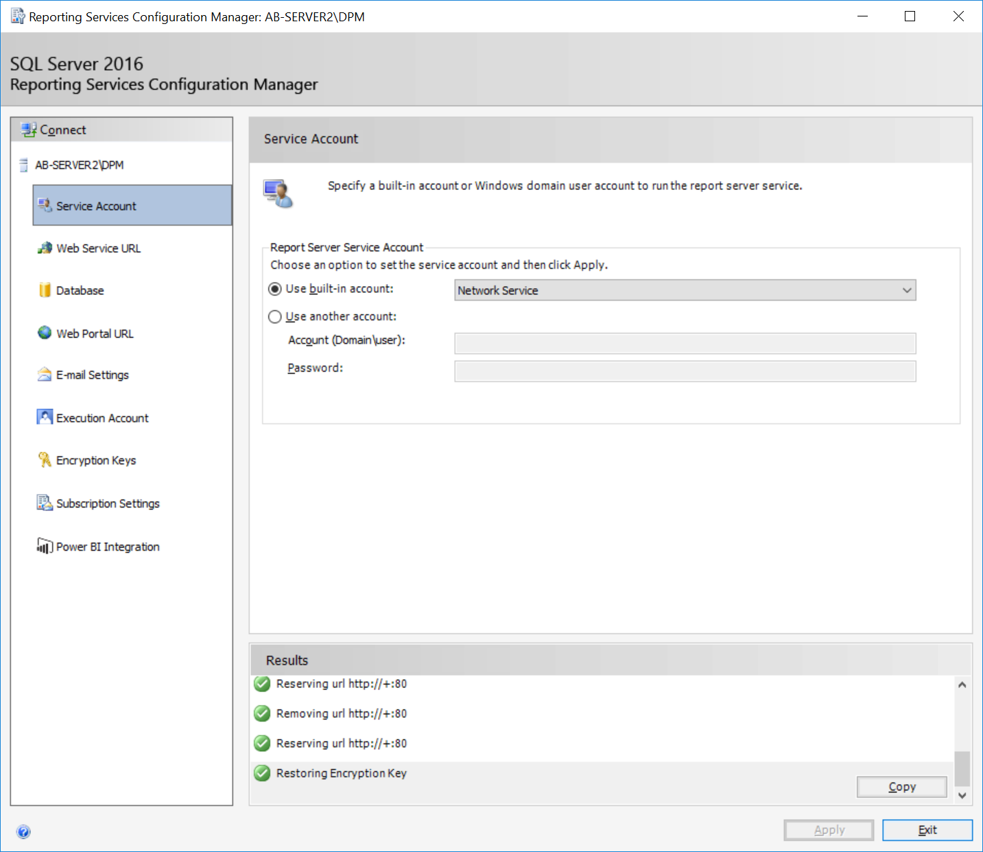
      1. Select the Service Account menu item
      2. Ensure Use built-in account is set to Network Service
        1. Check the Use built-in account radio button
        2. Set the account to Network Service
        3. Click Apply
        4. You will be prompted to save an encryption key. Save the key to location of your choosing, and type a password to be used to encrypt the file. Click OK
        5. You will then be prompted to specify an account with administrator privileges. Click OK to use your current account.
    9. Reboot the DPM Server

    At this point, you should now be able to schedule e-mail reports without experiencing the original error and your reports should load properly!