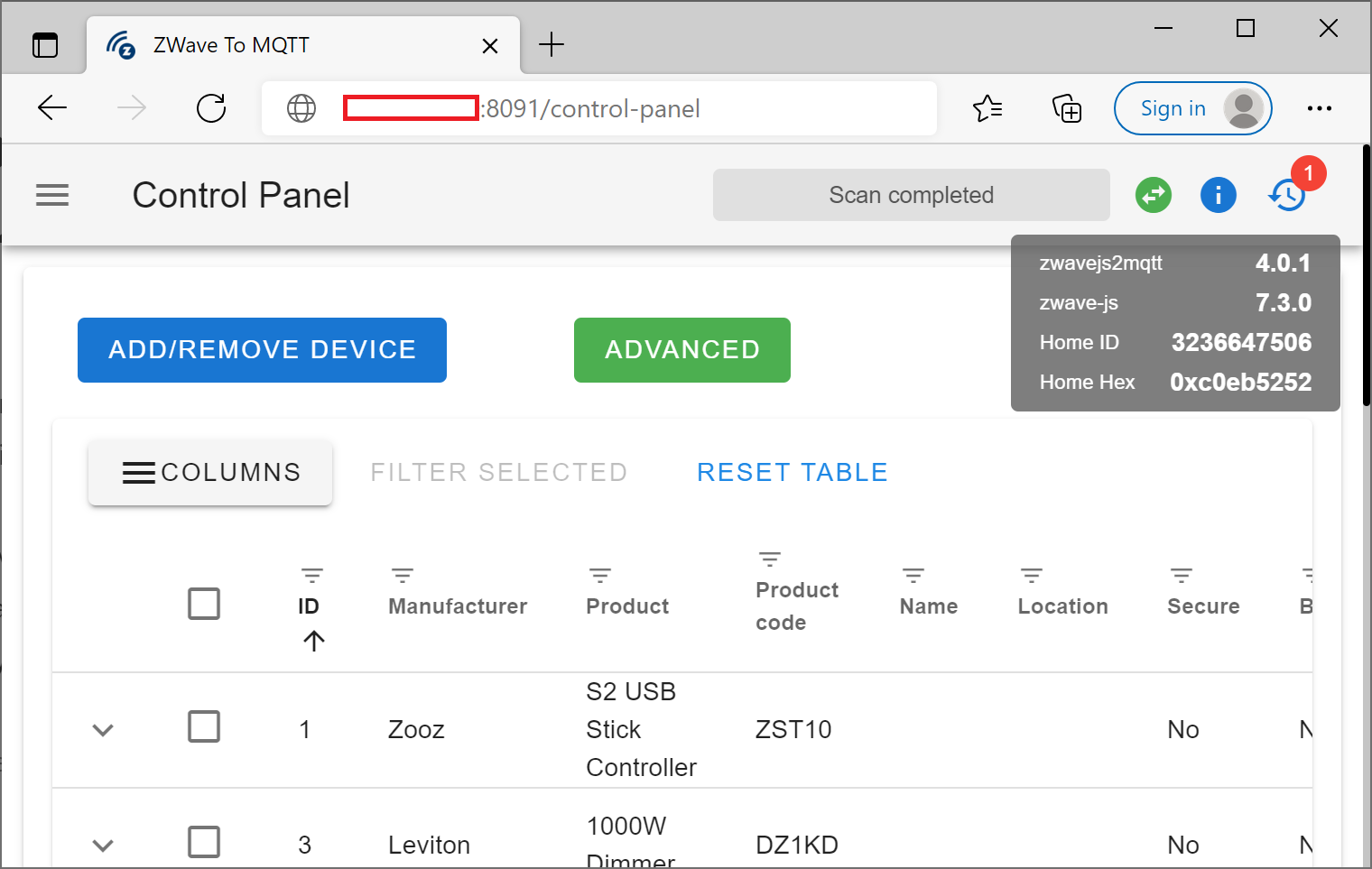
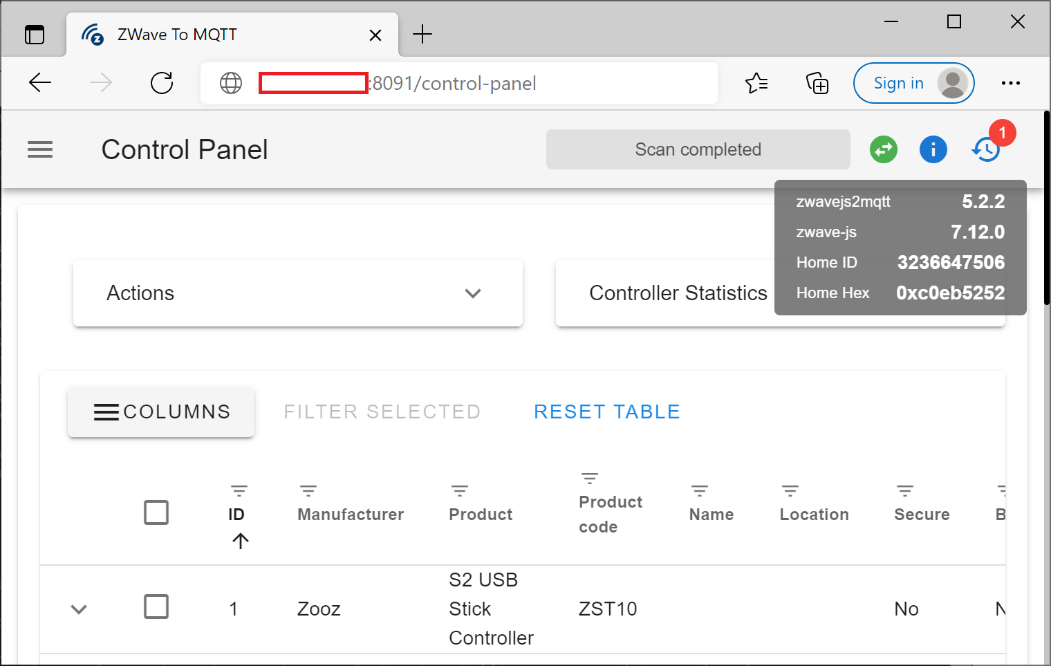
First, validate what version of Z-Wave JS you are running. To do this, navigate to the Z-Wave JS webpage and hover over the i icon to validate what versions of the software you are running. The Z-Wave JS webpage can typically be accessed at http://yourip:8091.
Get the current name of your container and version
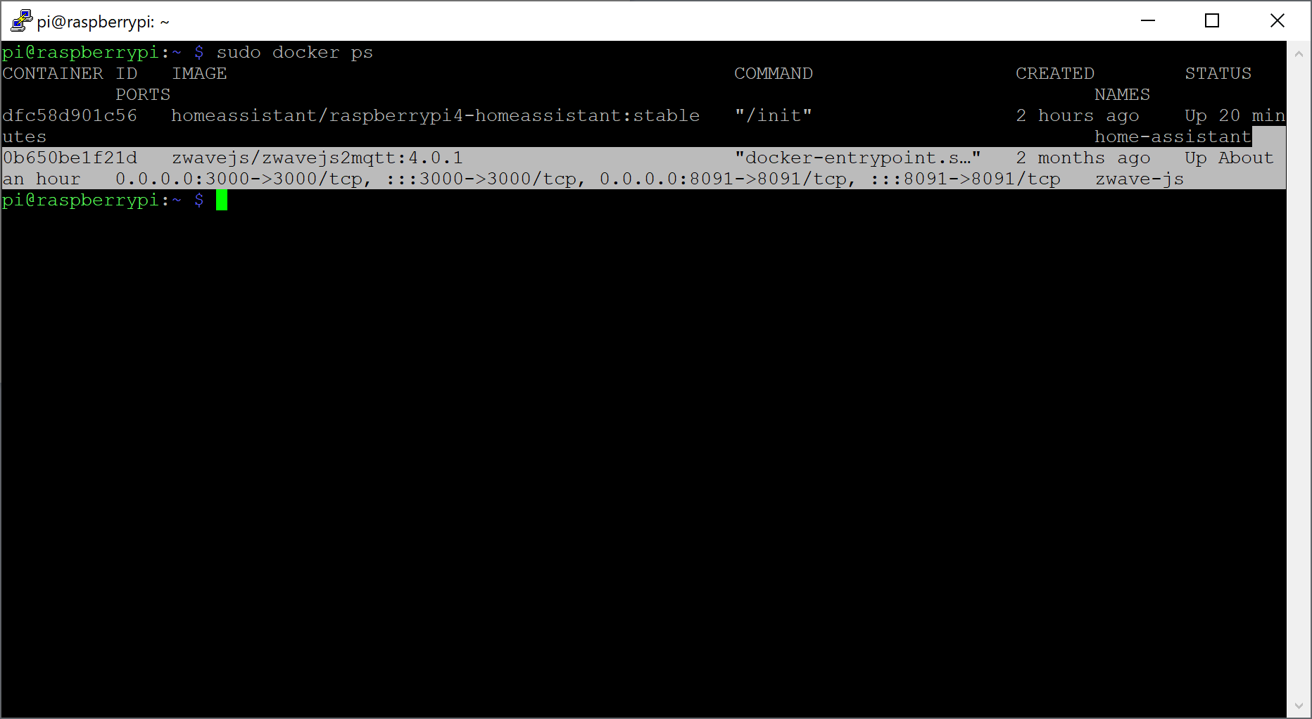
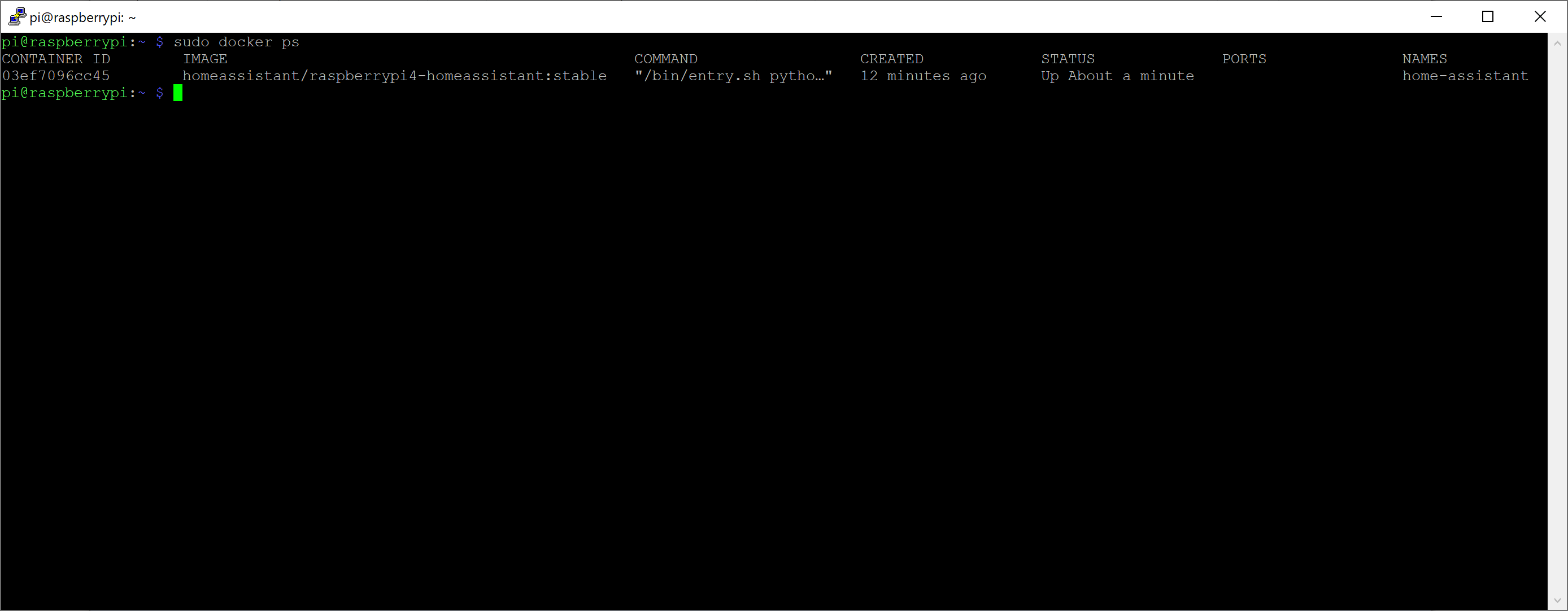
sudo docker ps
In running this command, note the NAME of your container as well as the IMAGE.
Stop and delete the container
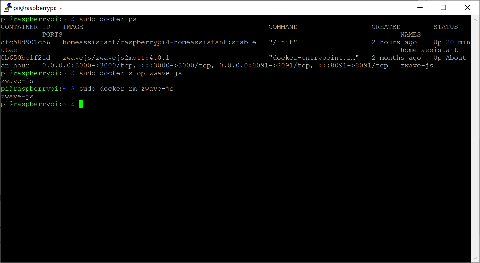
Replace the name of the container in the command below with the value you had.
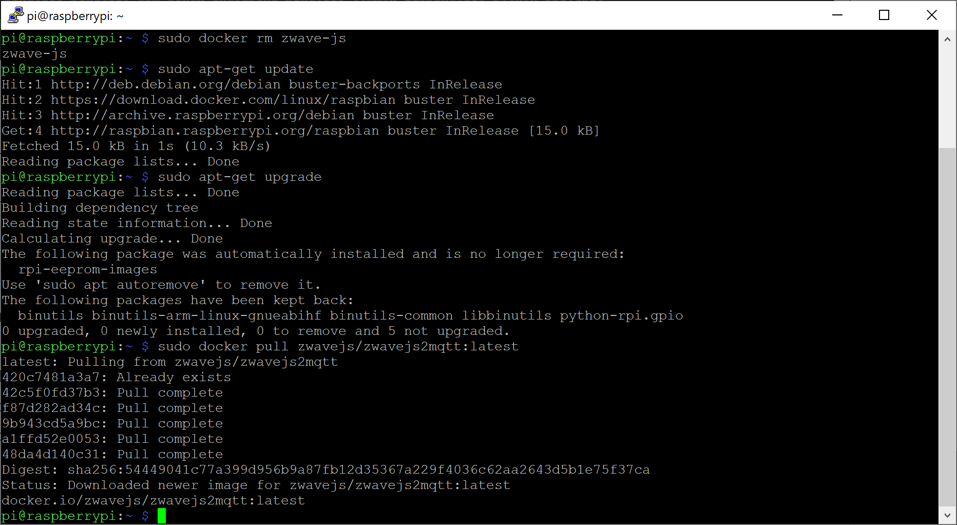
sudo docker stop zwave-js
sudo docker rm zwave-js
Update packages
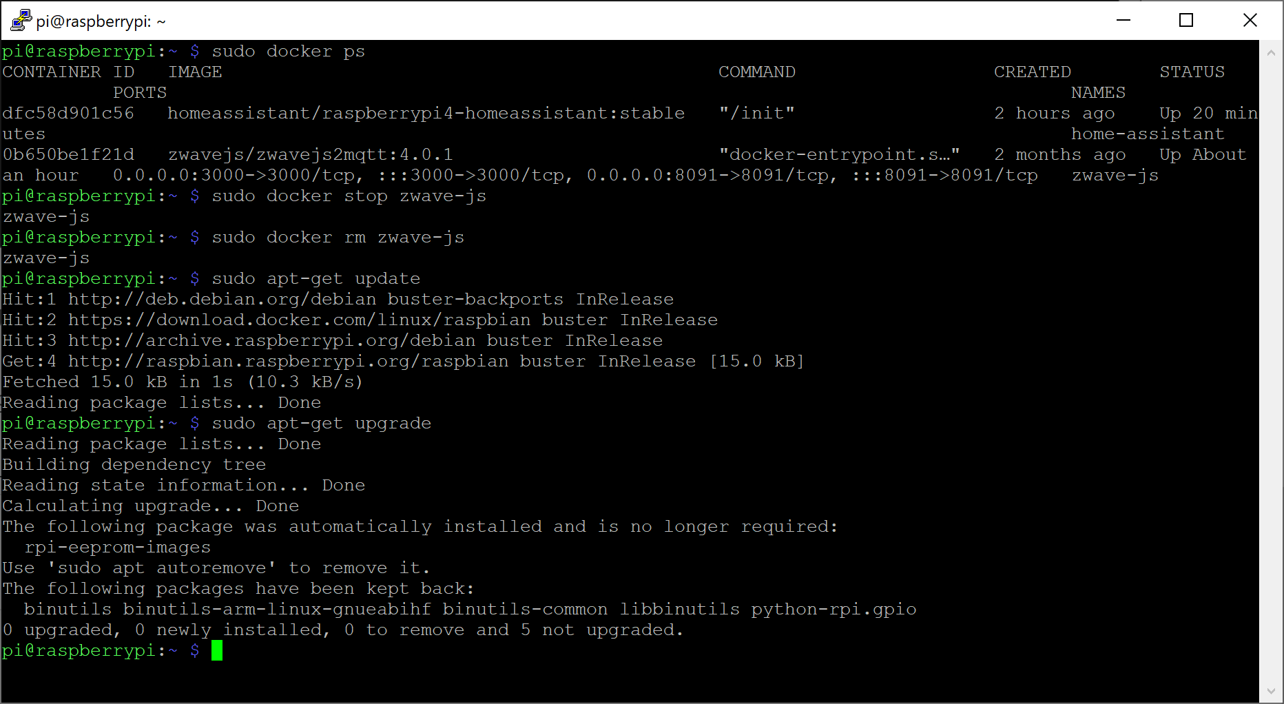
Some versions of HA require newer versions of Python, Docker, etc. I may consider updating to latest package versions first.
sudo apt-get update
sudo apt-get upgrade
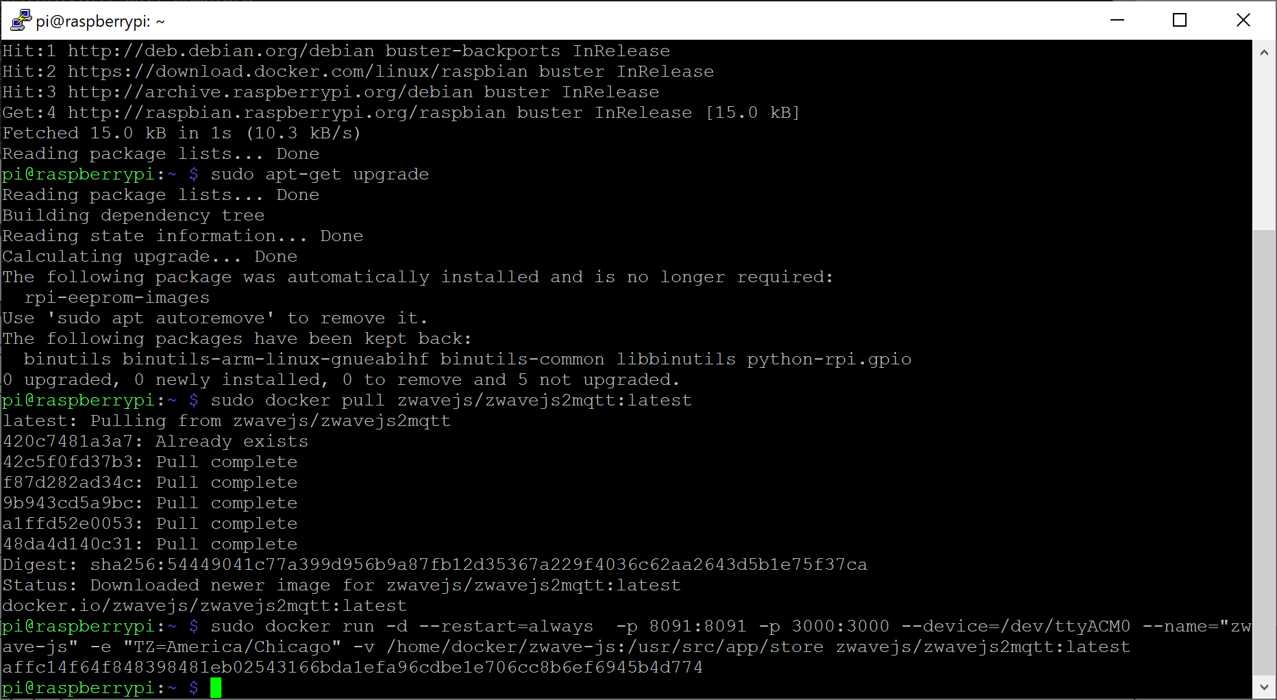
Pull the latest container from Docker Hub
Replace the value below with your IMAGE value you documented in the previous steps.
sudo docker pull zwavejs/zwavejs2mqtt:latest
Deploy the container
Make sure your replace the name and value of the image with the values in the previous step. In addition, ensure you specify the correct path to where you existing configuration files exist to have the container load your existing configurations.
Debian has a really good write up here on what backports are. Copying directly from their introduction paragraph:
You are running Debian stable, because you prefer the Debian stable tree. It runs great, there is just one problem: the software is a little bit outdated compared to other distributions. This is where backports come in.
Backports are packages taken from the next Debian release (called “testing”), adjusted and recompiled for usage on Debian stable. Because the package is also present in the next Debian release, you can easily upgrade your stable+backports system once the next Debian release comes out. (In a few cases, usually for security updates, backports are also created from the Debian unstable distribution.)
Backports cannot be tested as extensively as Debian stable, and backports are provided on an as-is basis, with risk of incompatibilities with other components in Debian stable. Use with care!
It is therefore recommended to only select single backported packages that fit your needs, and not use all available backports.
Once I enable backports will all packages use them?
No! Any new packages and updates to existing stable packages will prefer the stable releases. The only time you will leverage a new backport package is if you explicitly specify to pull from them.
How do I enable backports?
First you need to add the new backport source to your sources.list file. Edit the file in vi:
sudo vi /etc/apt/sources.list
Arrow down to the last row, press o to create a new line and then enter the following:
deb http://deb.debian.org/debian buster-backports main
Press escape and then type :wq to save the changes and exit via.
Next, we need to specify a keyserver to verify the authenticity of these packages. Note we use Ubuntu’s key servers to validate the packages. Interestingly, Debian has a keyring to validate the packages, however the keyring doesn’t contain the backports for buster on the raspberry pi at time of writing this. Ubuntu’s servers will work fine to validate the authenticity of these packages and you will ultimately pull the packages from Debian rather than Ubuntu.
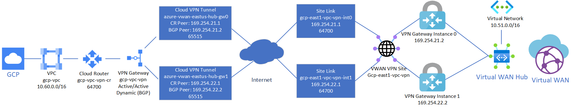
This is a quick reflection of the steps I took to establish two IPSec tunnels between GCP’s VPC and Azure’s Virtual WAN VPN Gateway, propagating routes dynamically via BPG and ensuring High Availability. The design is fairly straightforward since both GCP and Azure offer the ability to established multiple connections to remote peers. When everything is said and done, you’ll end up with a diagram that conceptually looks something like this:
Note: It is recommended to complete the steps in this document in the outlined order to complete the least amount of steps. In this case, provide Azure Virtual WAN first, then configure GCP, then create the Azure Virtual WAN Site Links / Connections to GCP.
Note 2: If you have followed my previous guide on establishing an AWS VPN tunnel to Azure Virtual WAN , this guide will co-exist both connections and can skip the Create Azure Virtual WAN and Virtual WAN Hub sections.
Create Azure Virtual WAN and Virtual WAN Hub
On the Azure side, first we need to create a Virtual WAN resource and a Virtual WAN Hub, which will contain our VPN Gateway. If you have already created these, you can skip to the next session.
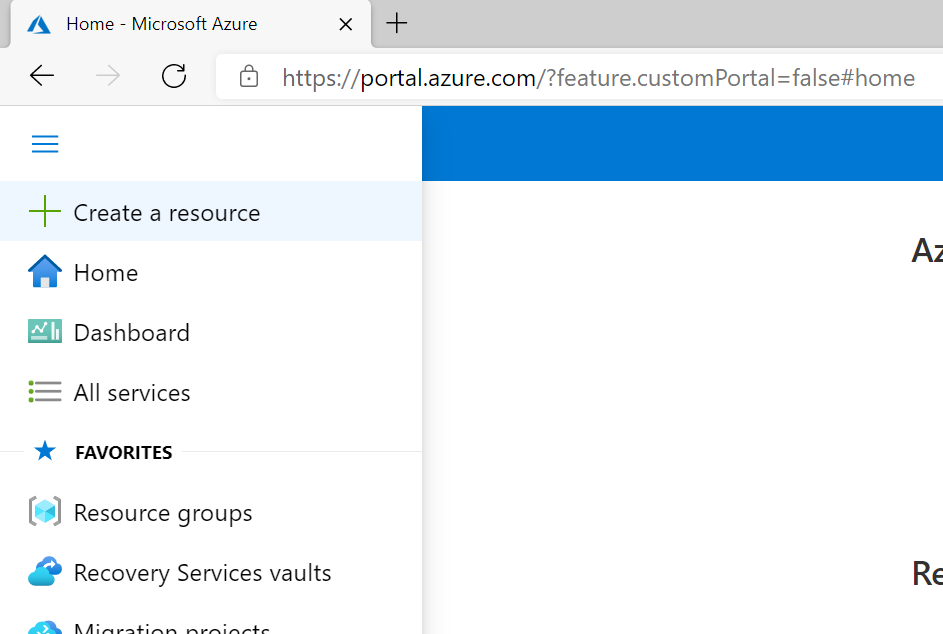
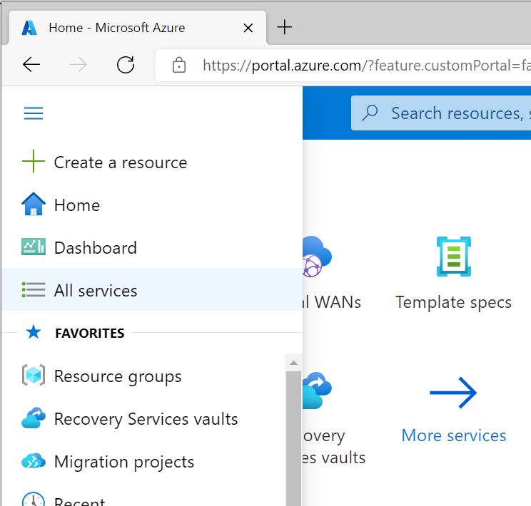
First, click the “Hamburger” icon and select Create a resource
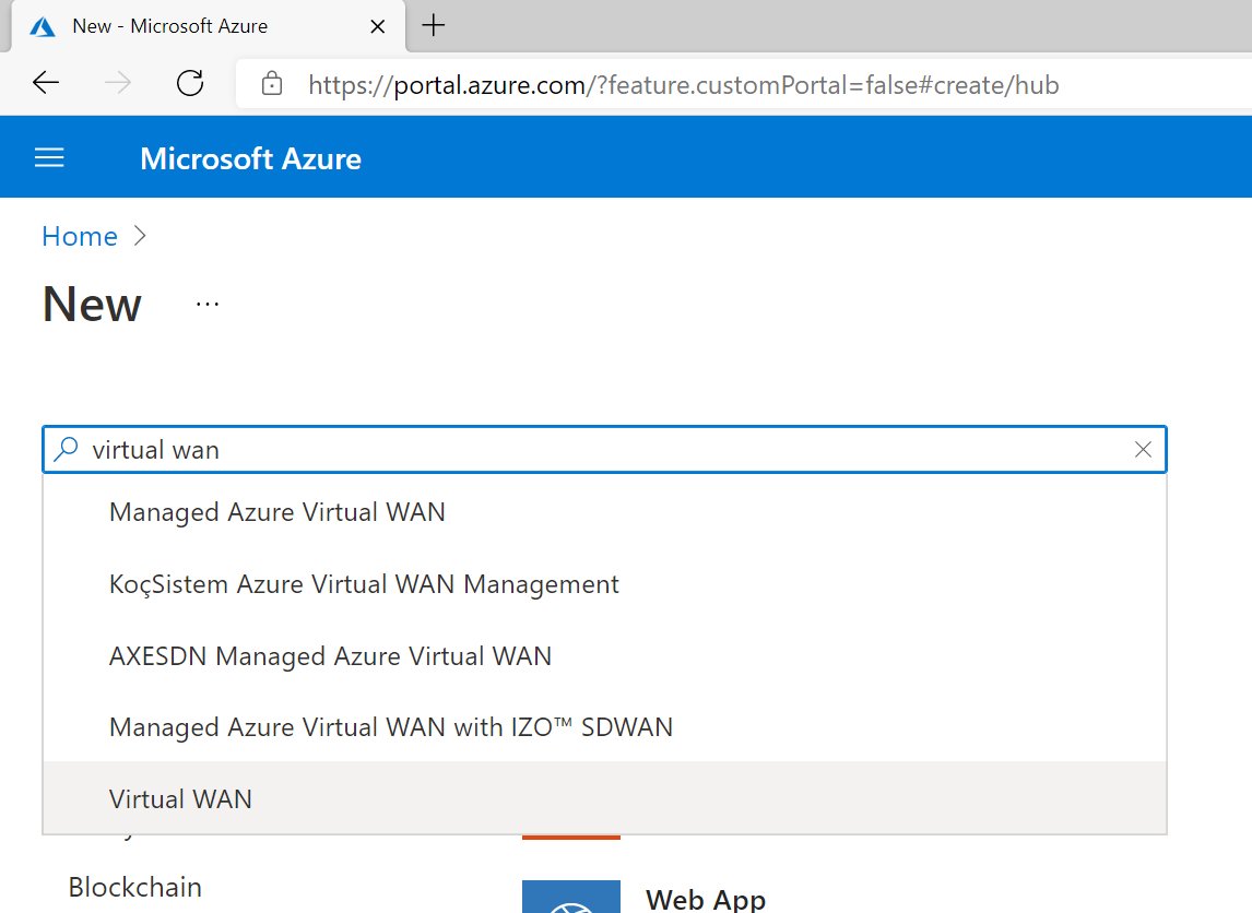
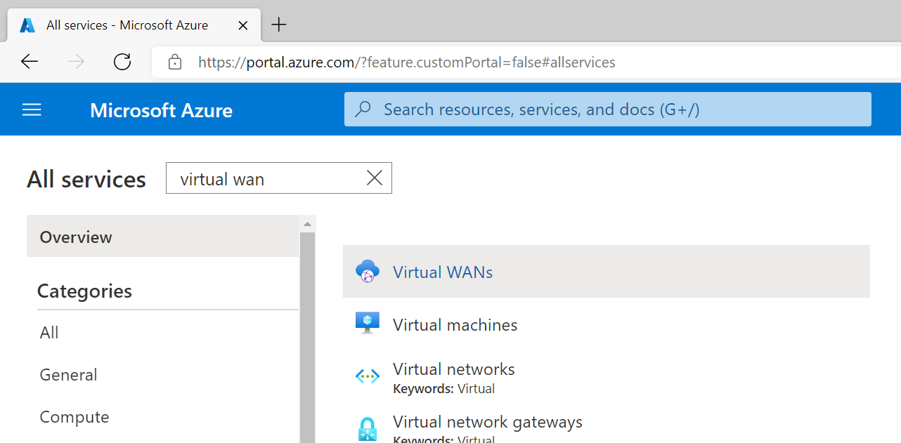
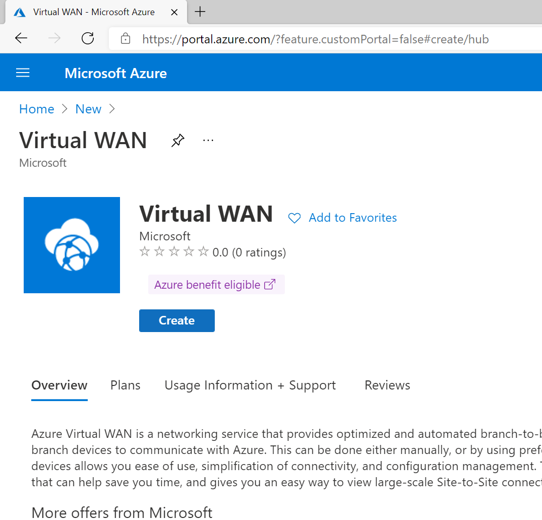
Search for Virtual WAN and select it from the list in the marketplace.
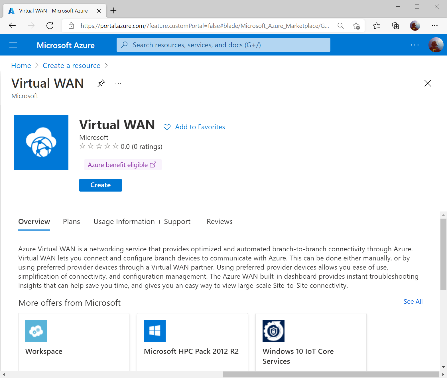
Select Create
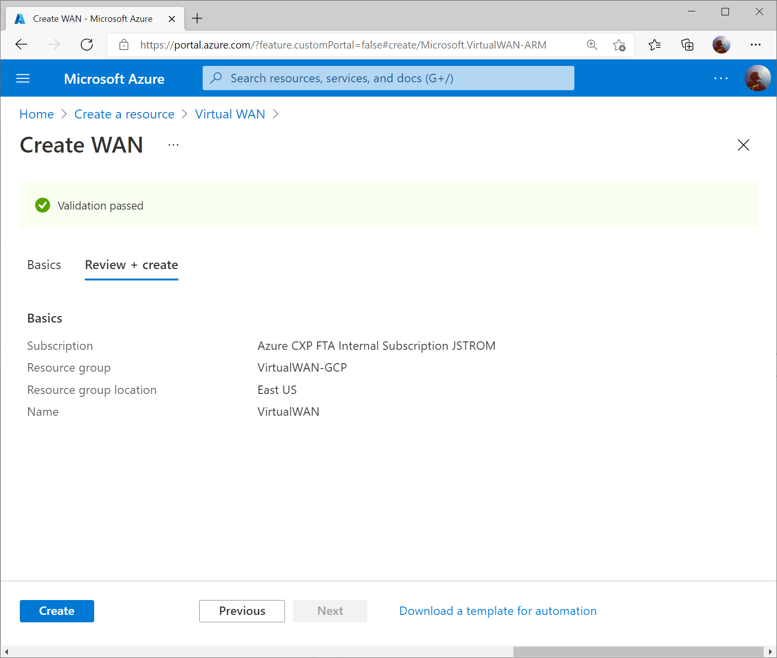
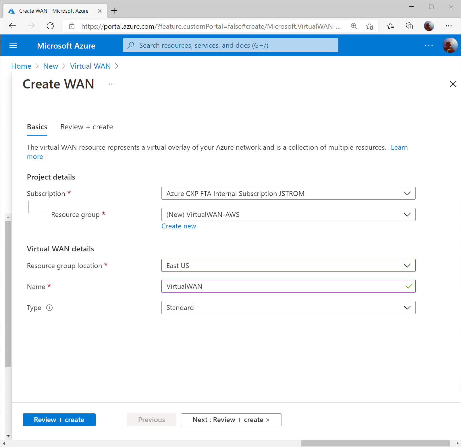
Specify the resource group and region you wish to deploy the Virtual WAN resource to. Specify a name for your Virtual WAN resource and click Review + Create
Click Create to start provisioning the Virtual WAN resource.
Once the resource is created, click Go to resource to navigate to your Virtual WAN resource.
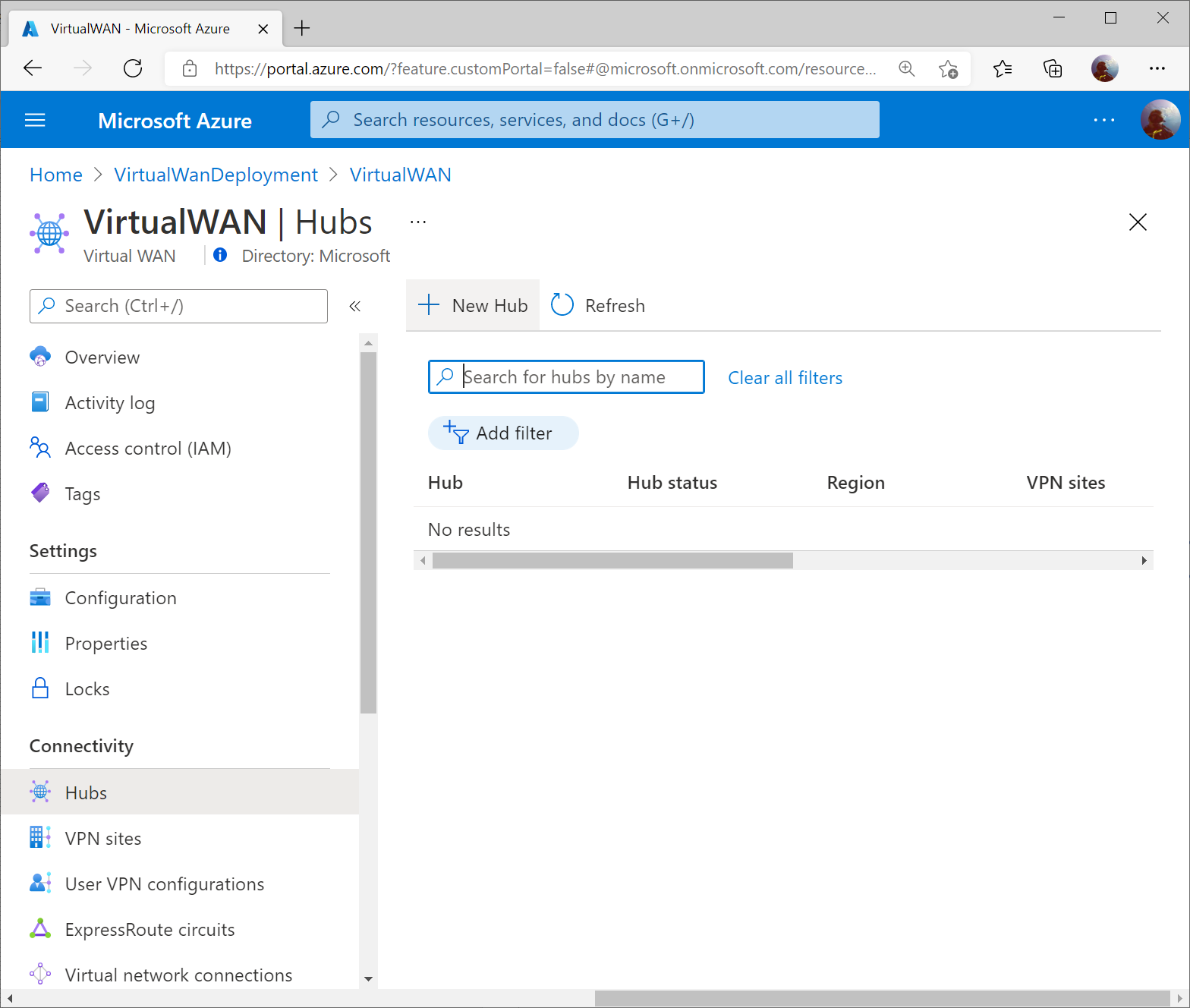
On the Virtual WAN resource, select New Hub from the top menu.
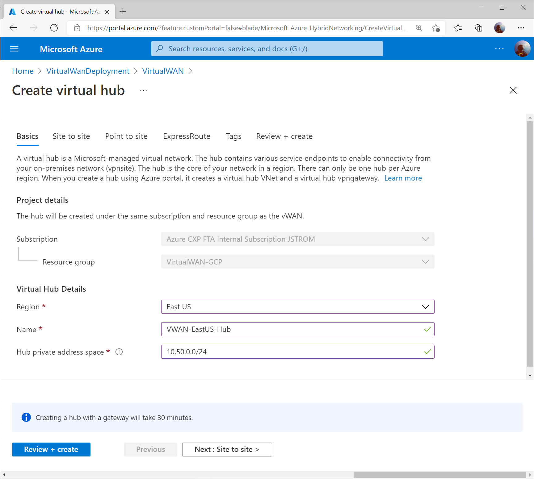
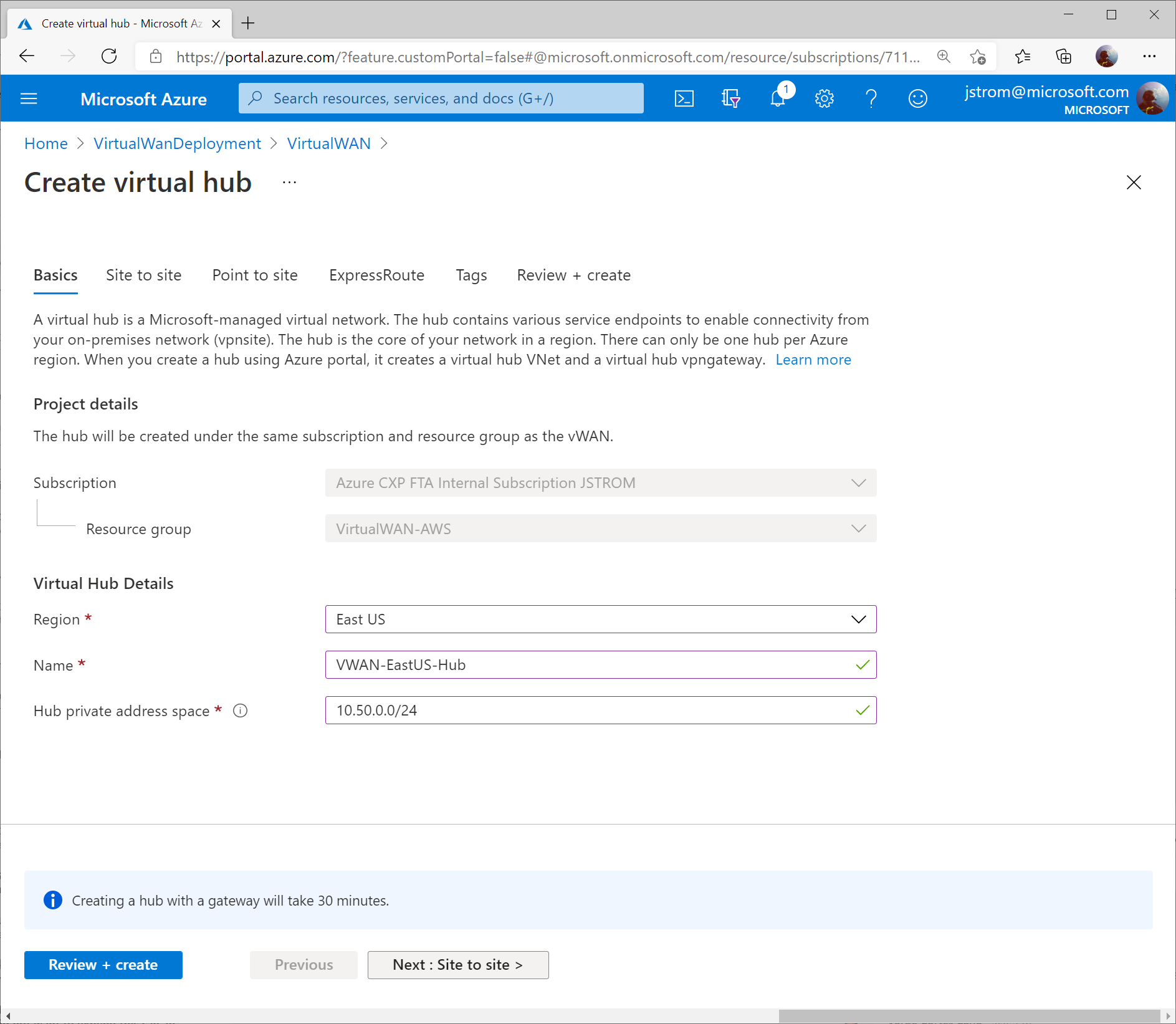
Specify the name of the Hub and an address space that can be used for all the networking components Virtual WAN will deploy into the Virtual Hub. Click Next : Site to Site >
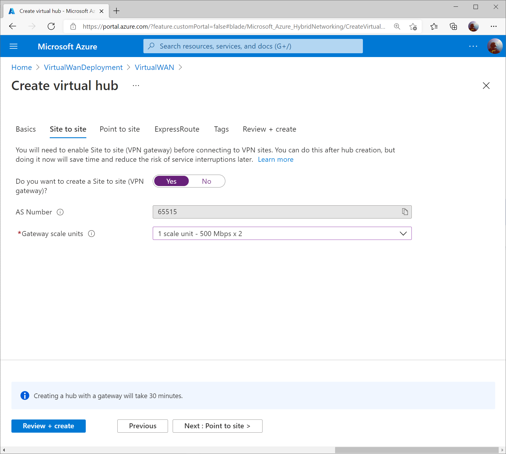
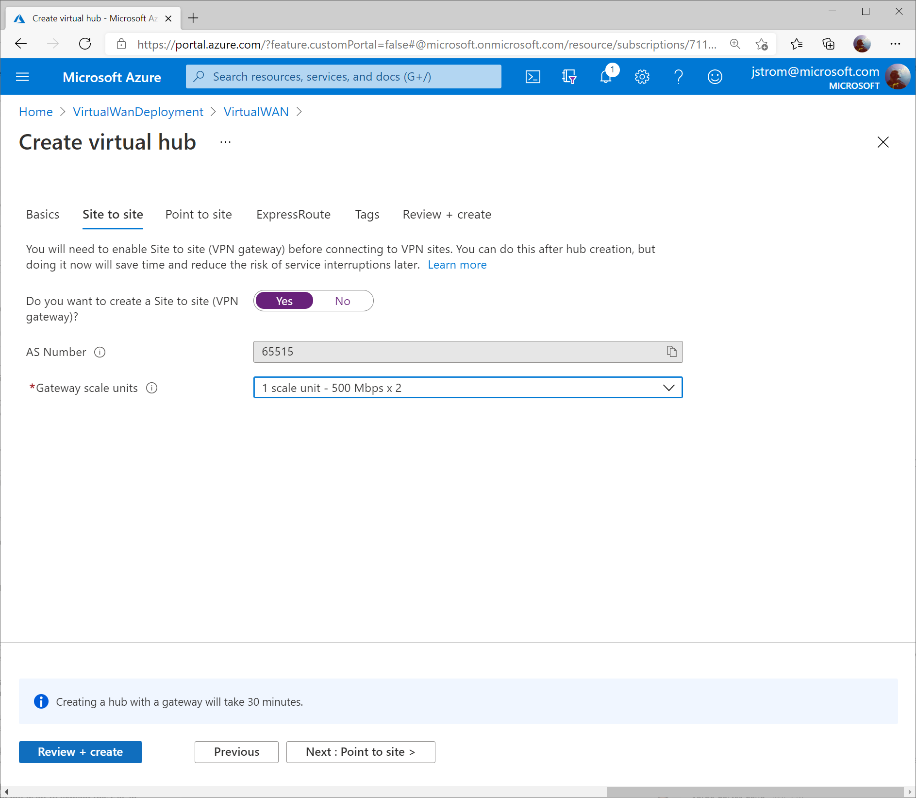
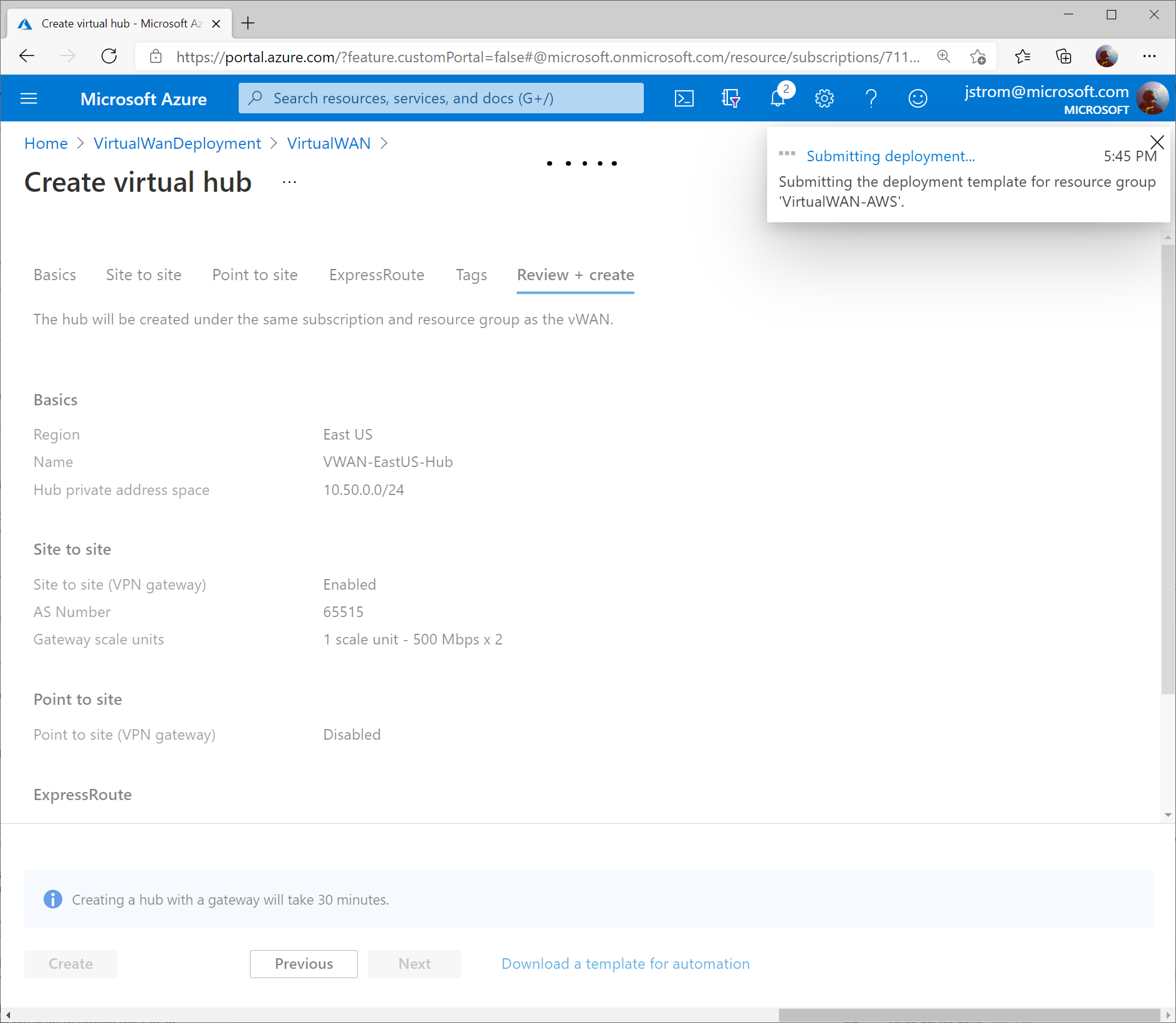
On the Site to Site tab, toggle Yes that you want to provision a VPN Gateway, and specify the scale units you need. Click the Review + create button when done.
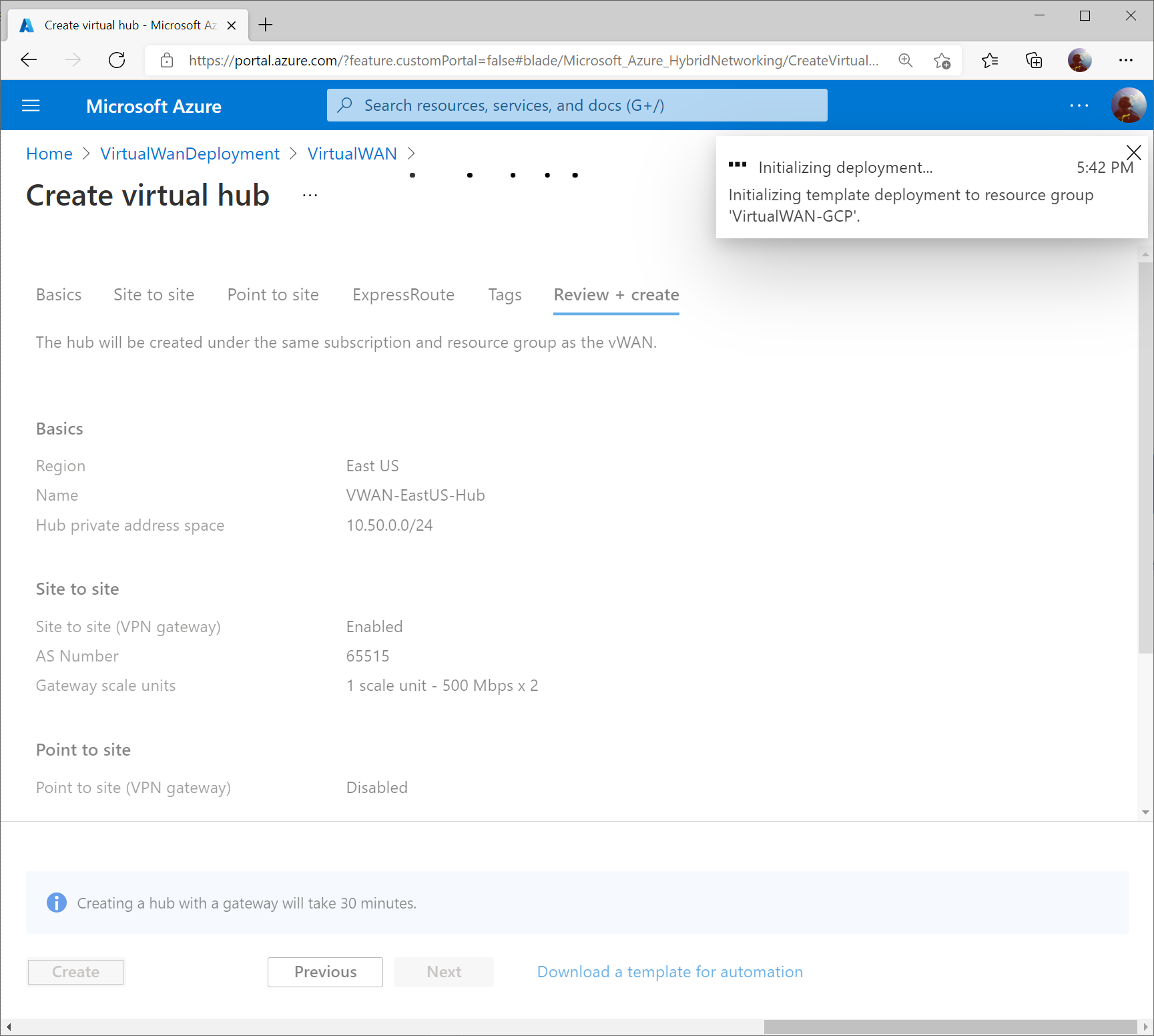
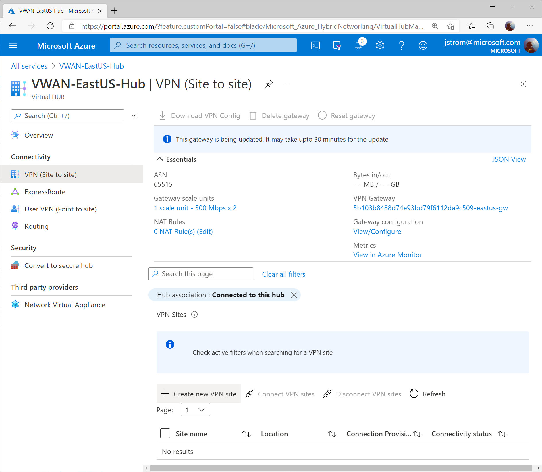
Click the Create button to start provisioning the Hub and VPN Gateway. Please note this can take up to 30 minutes to complete.
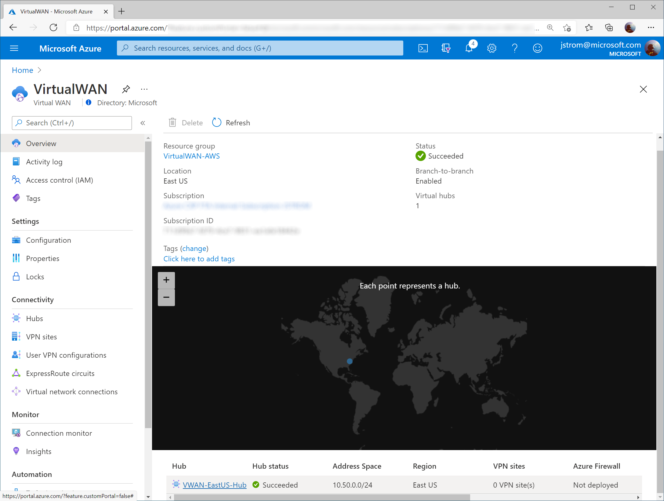
Once the Virtual WAN Hub has been created, click the Menu icon and select All services (note: if you click the Go to resource button after the Virtual WAN Hub resource is created, it’ll take you the properties of the Hub, which isn’t where we want to be).
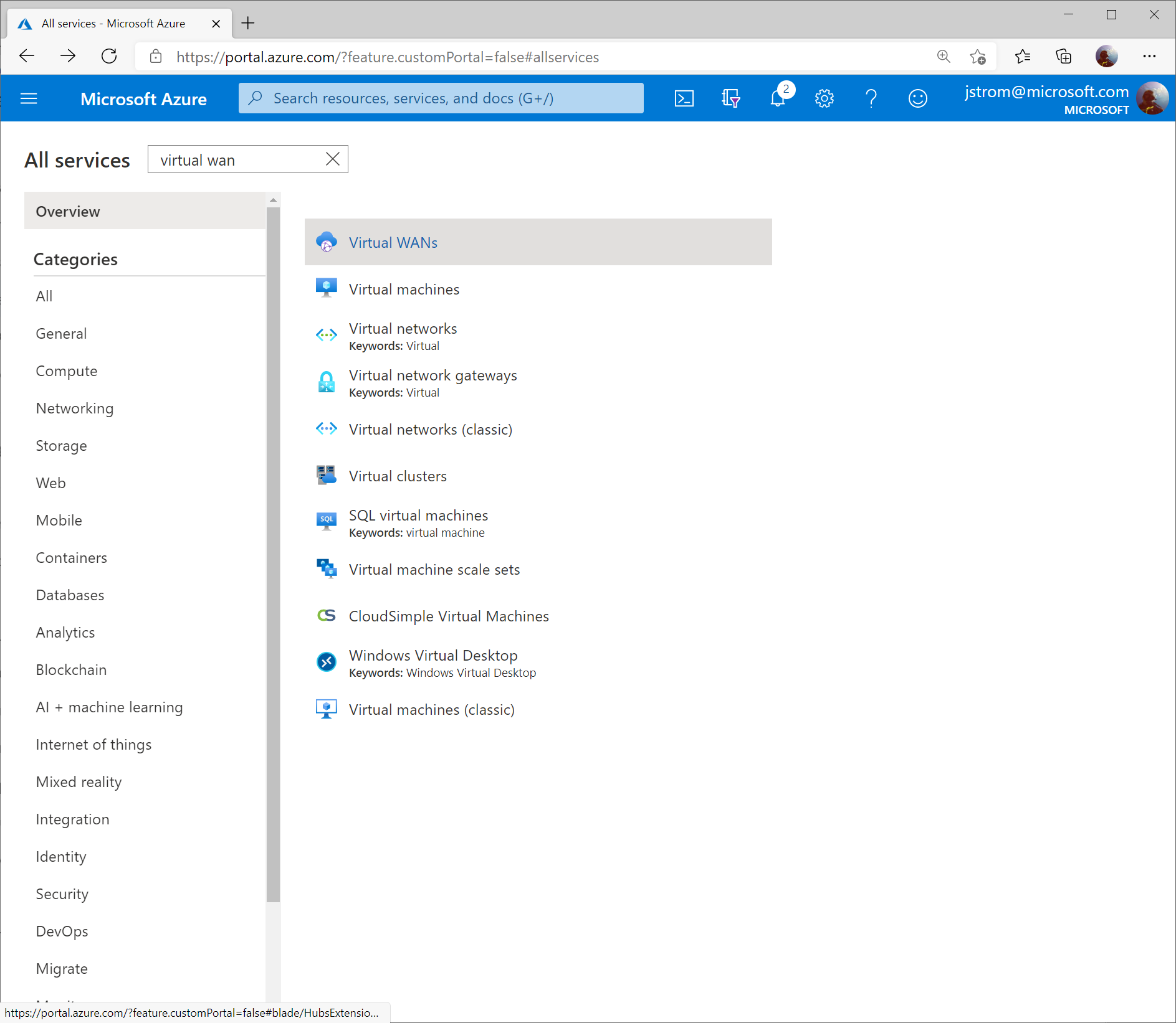
Search for Virtual WAN and select Virtual WANs.
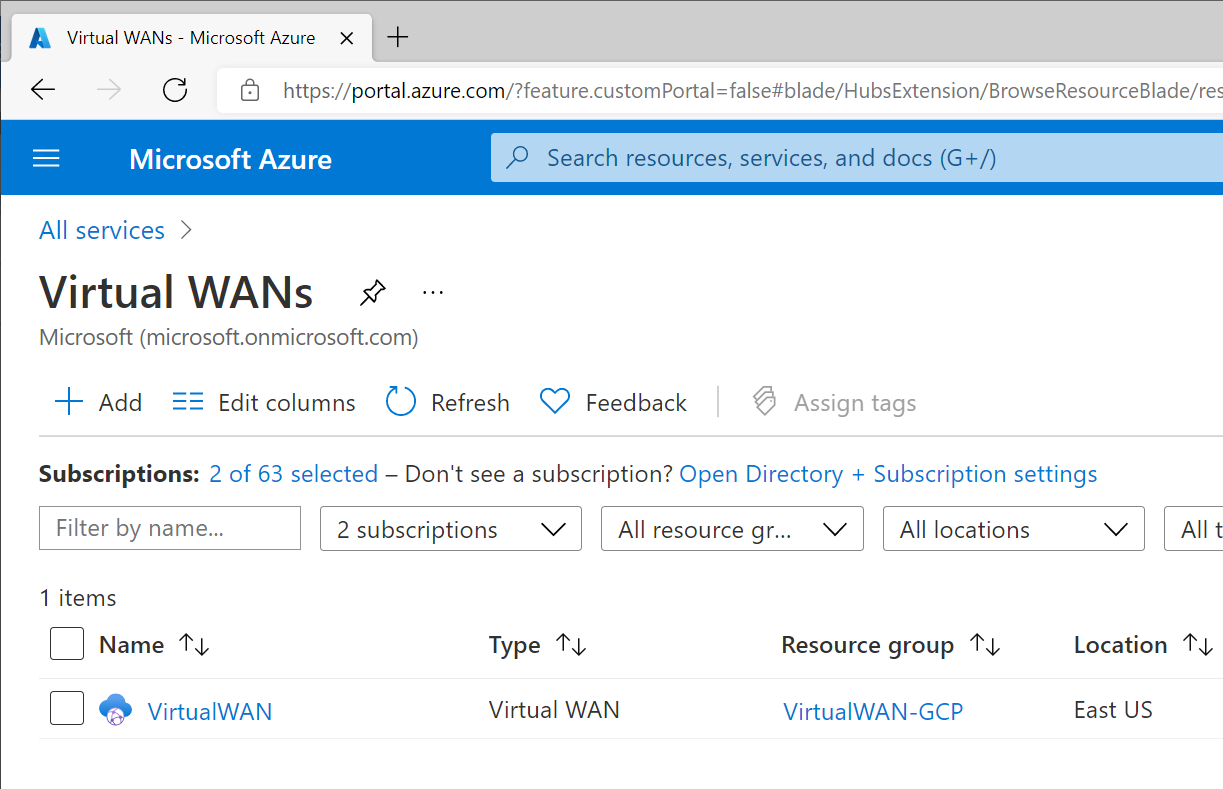
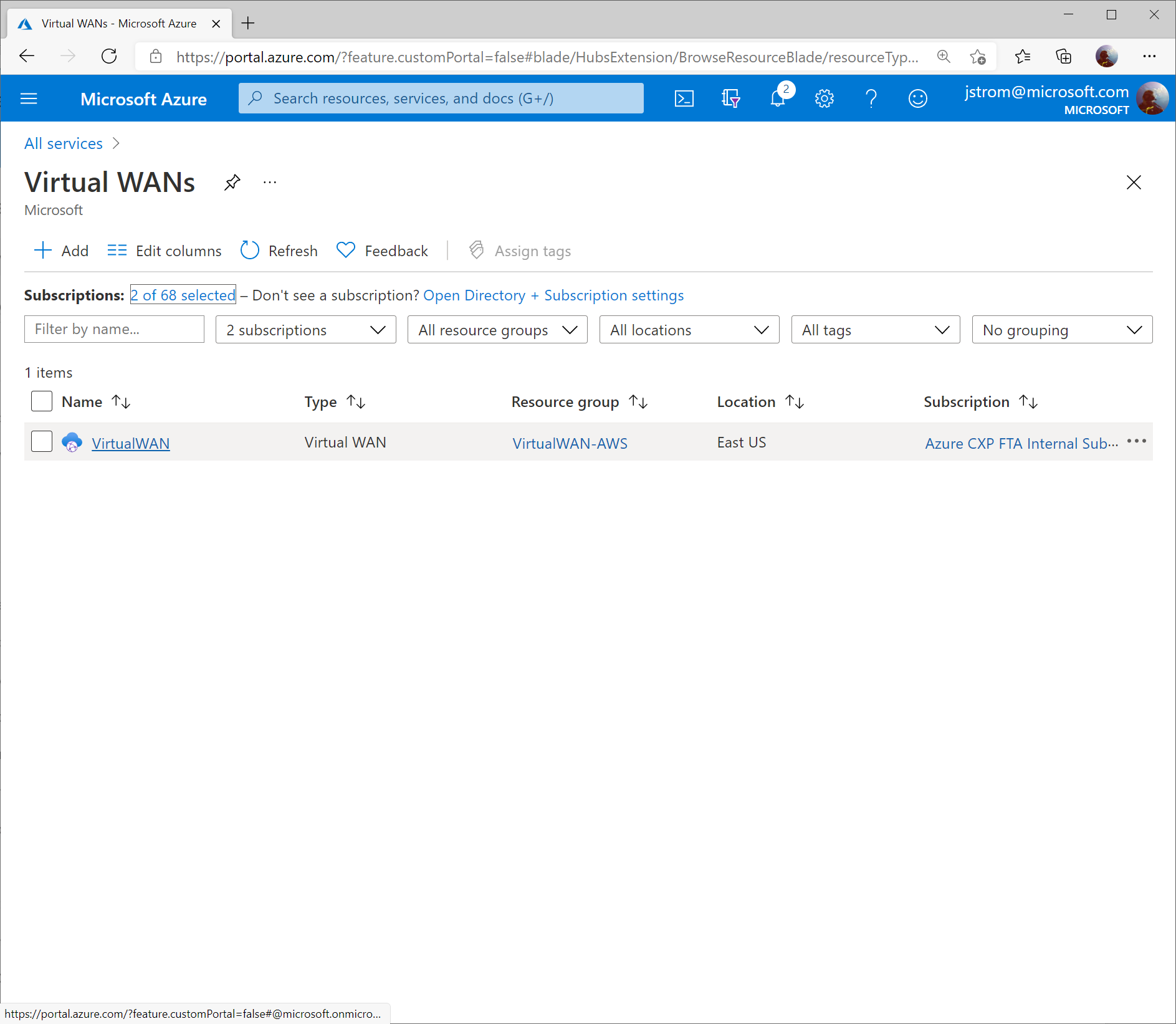
Select your Virtual WAN resource.
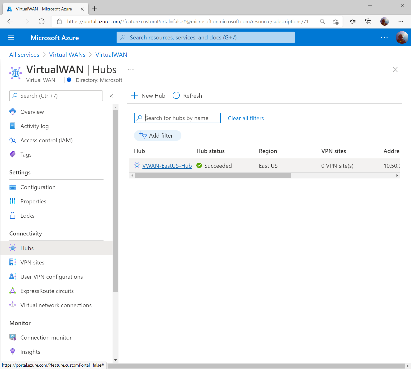
Click on Hubs under Connectivity and select your Virtual WAN Hub.
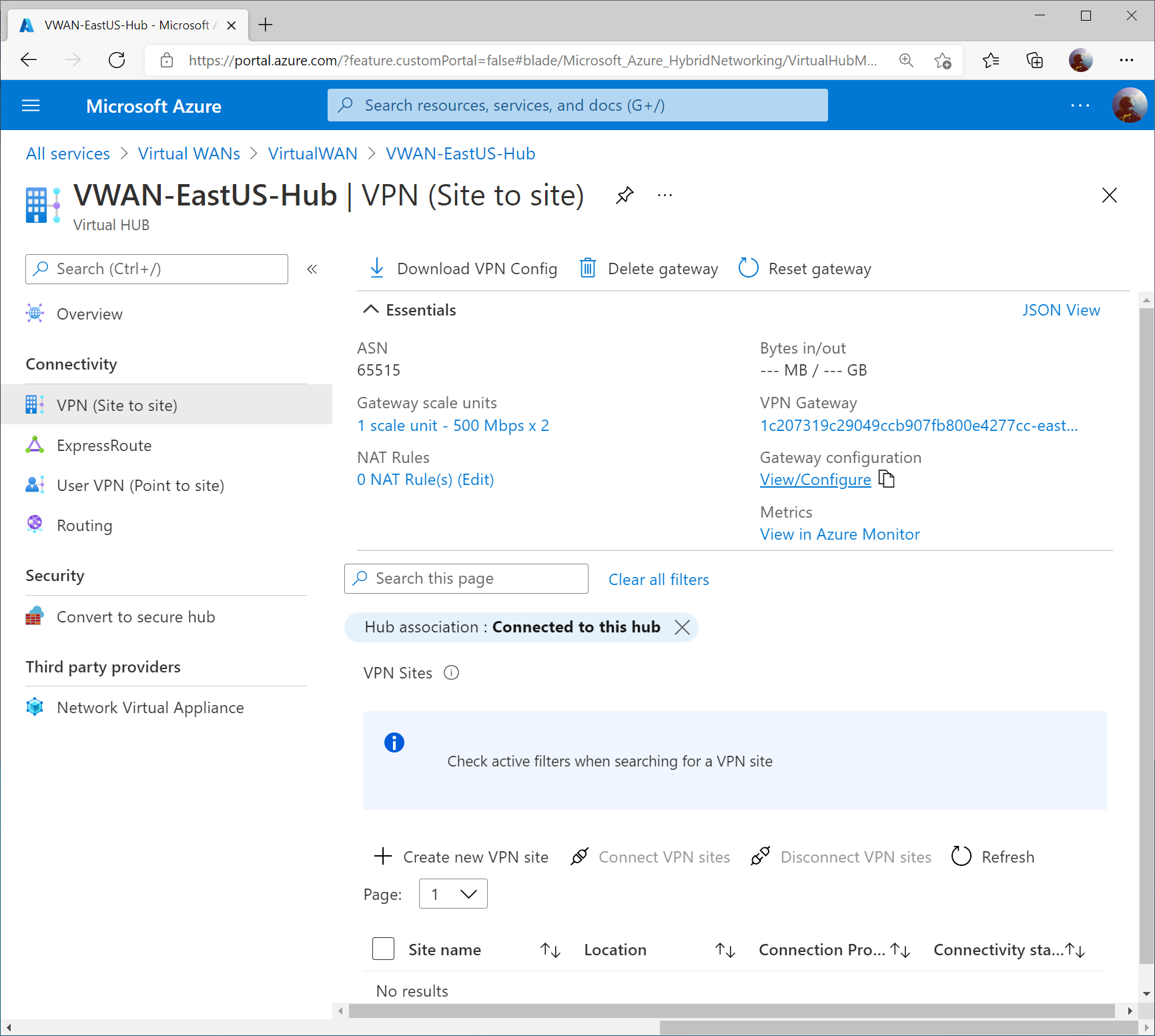
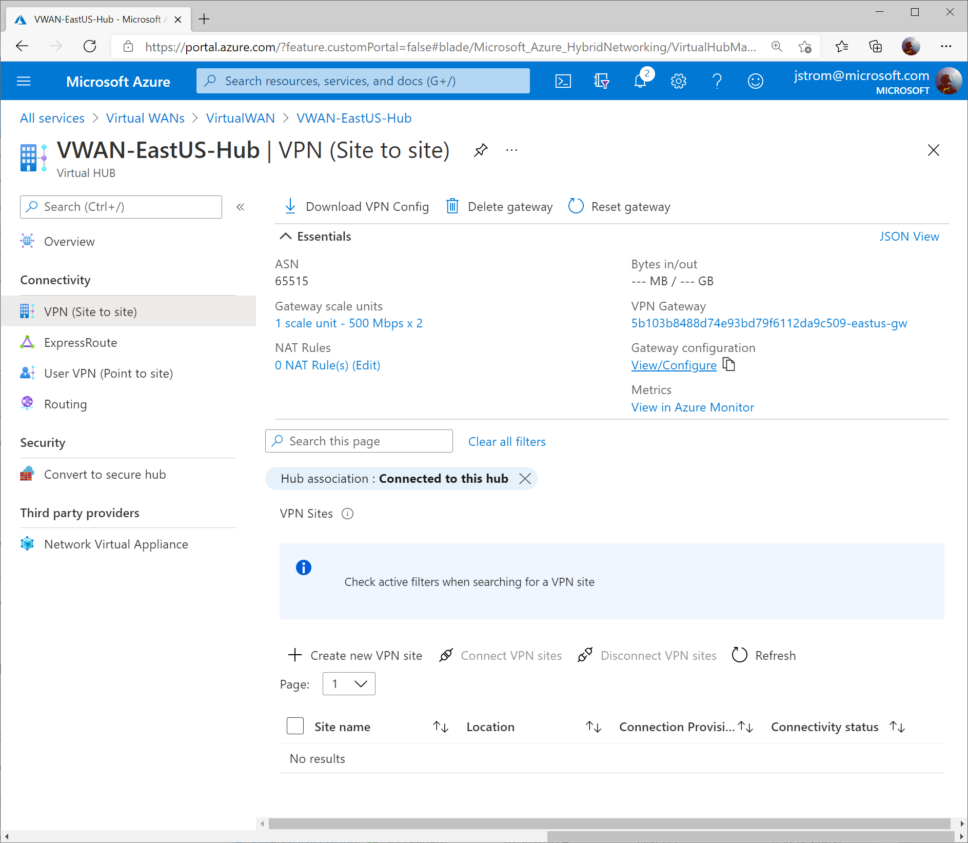
Select VPN (Site to Site) under Connectivity and then click on the View/Configure link.
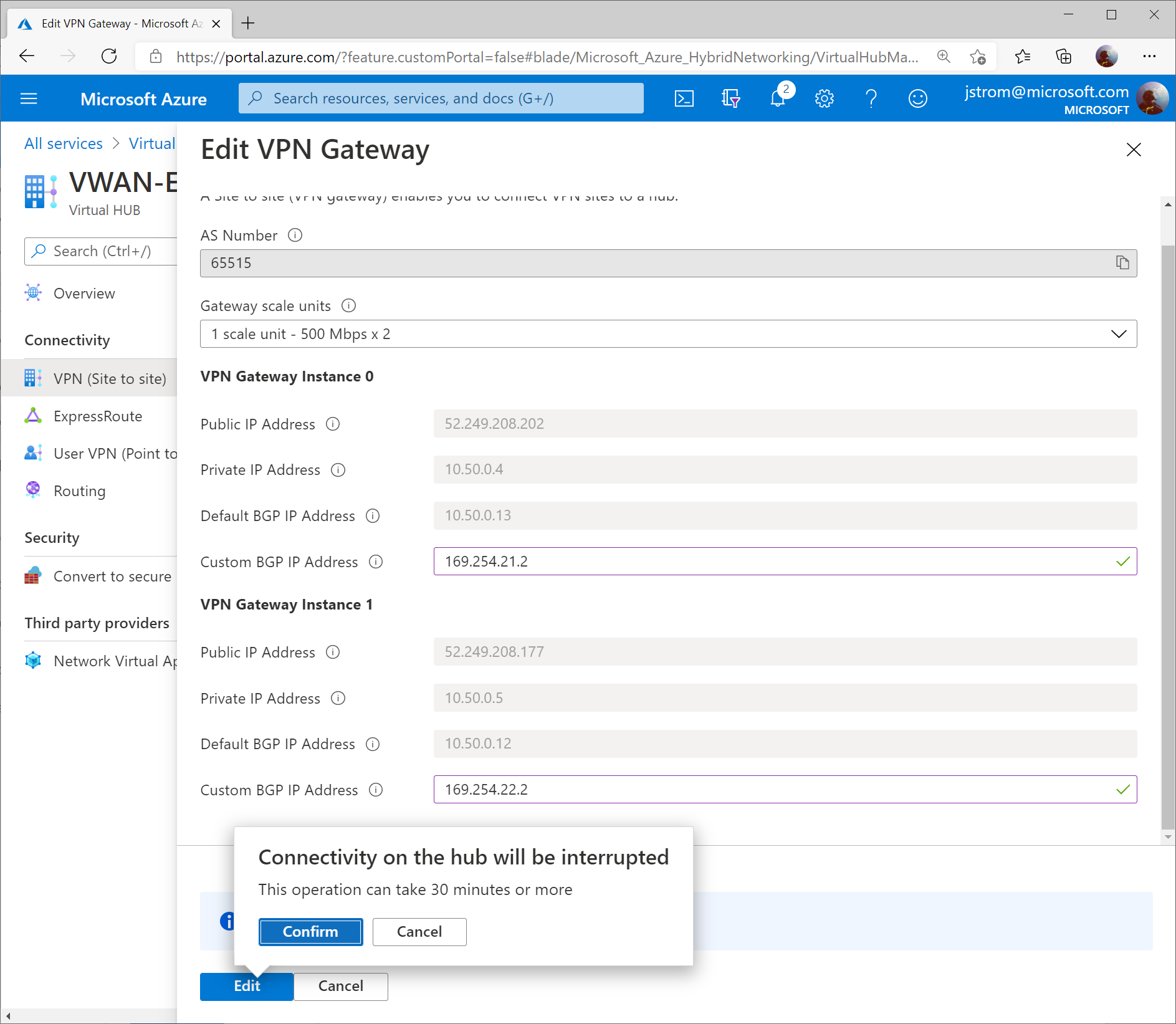
Set the Custom BGP IP addresses for each instance. Use the values below:
VPN Gateway Instance 0: 169.254.21.2
VPN Gateway Instance 1: 169.254.22.2
Click Edit once completed.
Configure GCP
Prerequisites
This guide assumes you have a VPC already (in my case, mine is called GCP-VPC with an address space of 10.60.0.0/16) and corresponding set of subnets for your servers.
Note: A GCP VPC is the equivalent of a VNet in Azure. One thing that is different between GCP and Azure is that in GCP you do not need to specify a subnet for your Gateways (i.e. “GatewaySubnet”).
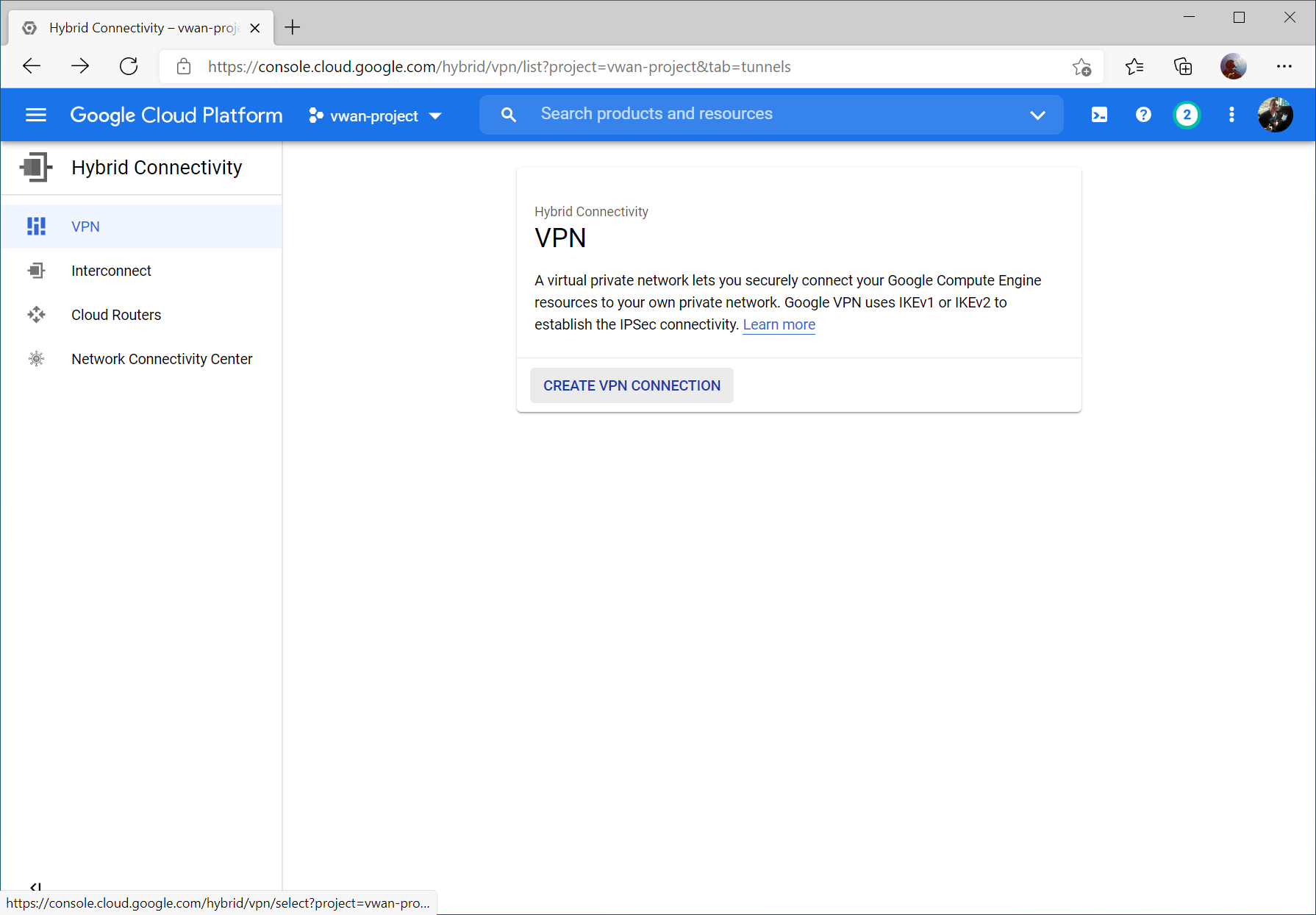
Within the GCP Console, select Hybrid Connectivity -> VPN
Click Create VPN Connection
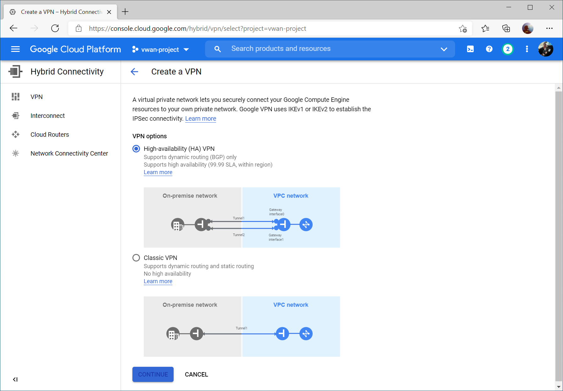
Select High-availability (HA) VPN and select Continue
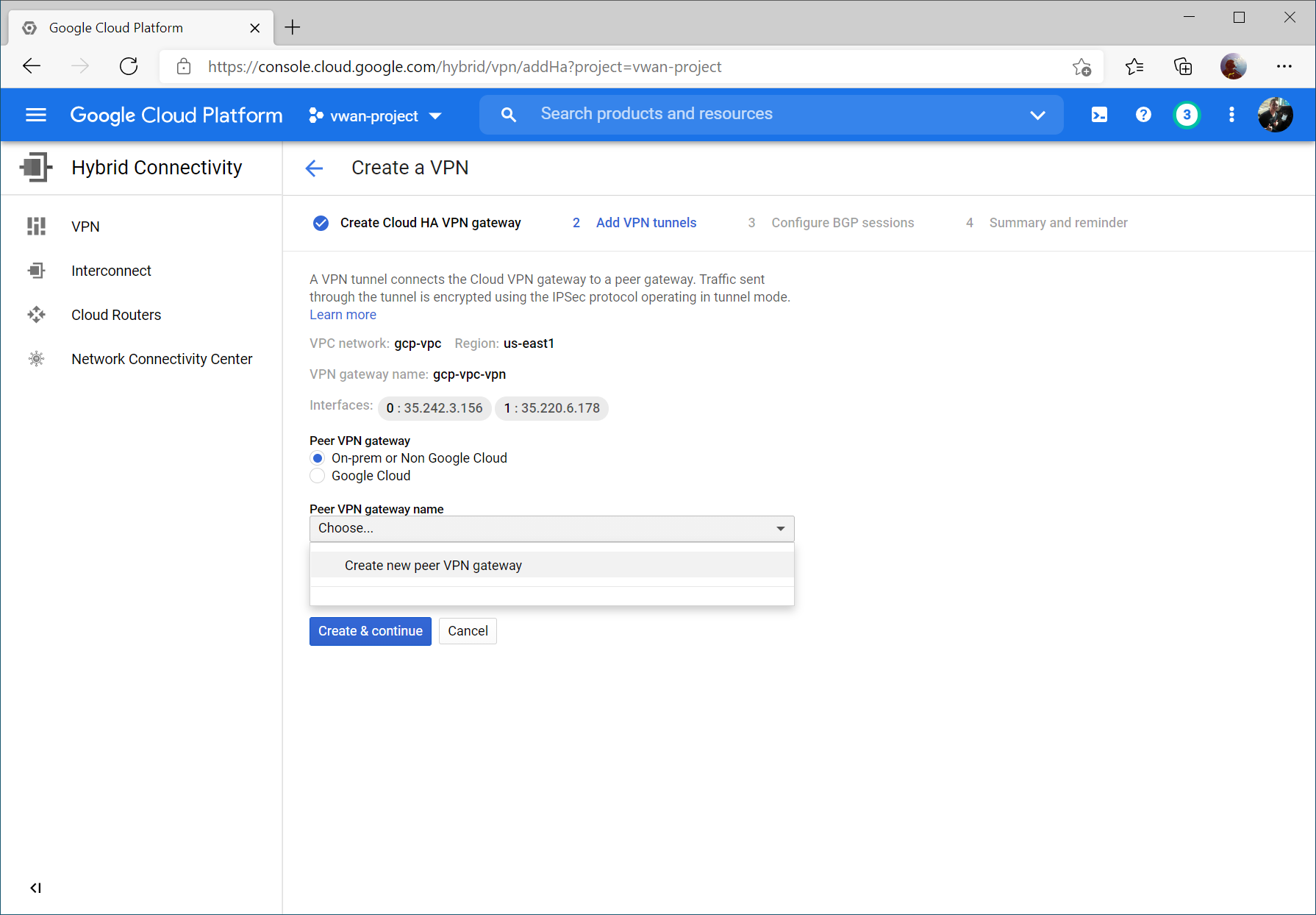
Enter a name, select your VPC, and specify a region. Click Create & Continue.
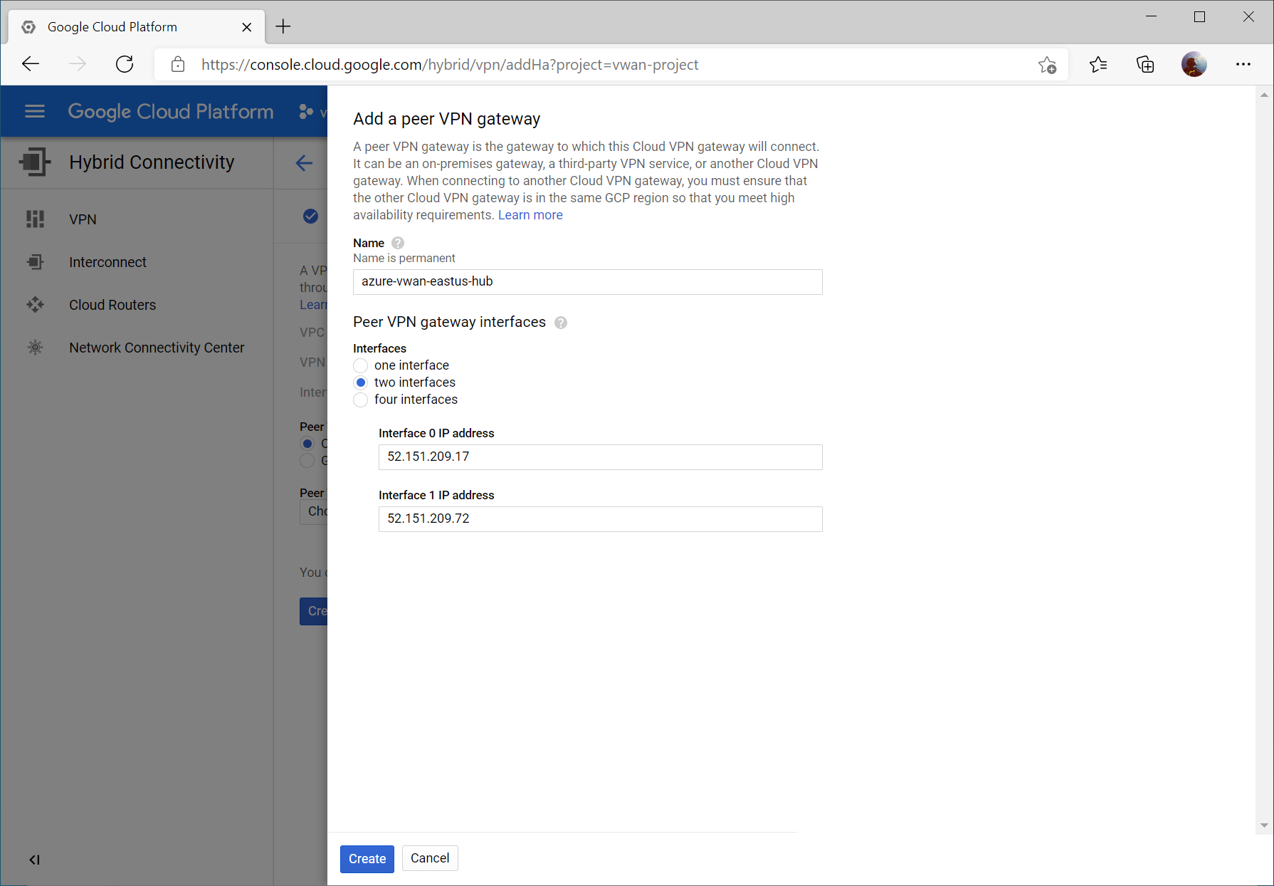
Write down your Interface public IPs (we’ll use these later) and check On-prem or Non Google Cloud for Peer VPN Gateway. Click Create & continue.
Select two interfaces and enter your Instance 0 and Instance 1 Public IP addresses from your Virtual WAN Hub’s VPN Gateway. Click Create.
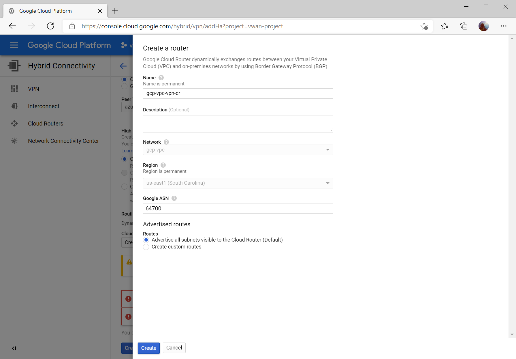
Click the dropdown for Cloud Router and select Create a new router
Enter a name and description for your router. For the ASN, enter a unique ASN to use (I used 64700 to differentiate from Azure as well as the ASN I used in the AWS example (which was 64512)). You can specify any supported ASN for this, however I would recommend against using 65515 specifically as this is reserved by Azure’s VPN Gateways.
Note: Google ASN must be an integer between 64512 and 65534 or between 4200000000 and 4294967294 or 16550
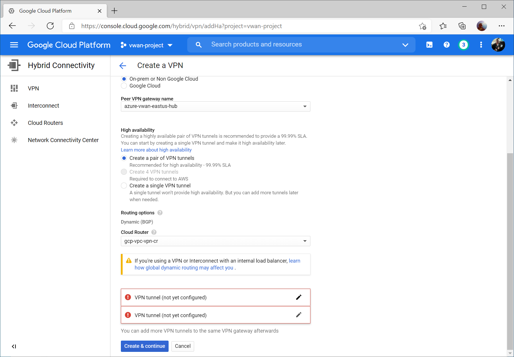
Click the pencil icon to modify the first VPN tunnel.
Select the instance 0 VPN Gateway interface, enter a name, set the IKE version to IKEv2, enter a pre-shared key, and click Done.
Repeat the same steps for the second VPN tunnel, specifying instance 1 VPN Gateway interface, enter a name, set the IKE version to IKEv2, enter a pre-shared key, and click Done and then Create & continue.
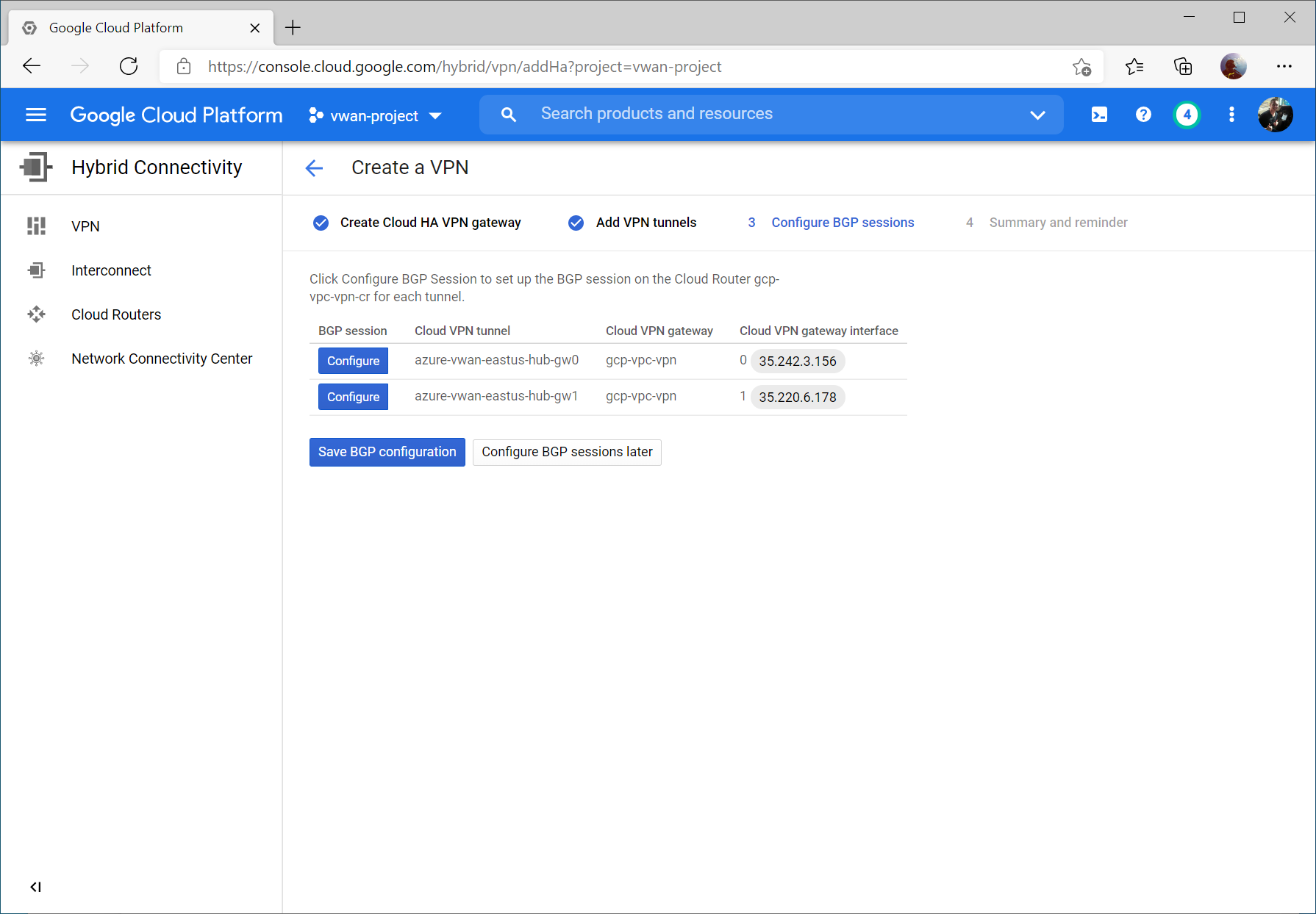
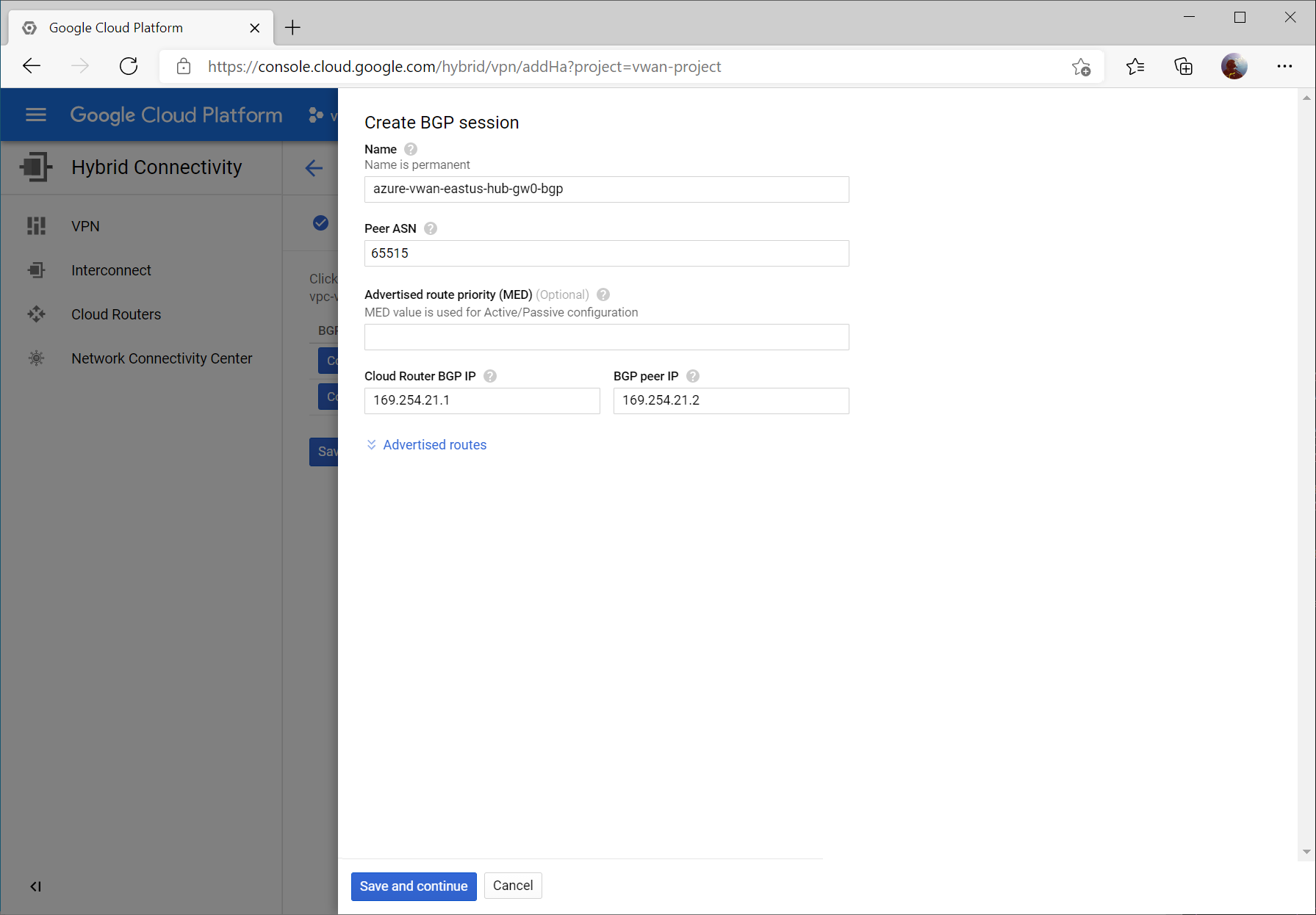
Click the Configure button for the first BPG session.
Enter a name for the first BGP peer connecting to instance 0 gateway on Virtual WAN.
Specify Peer ASN of 65515 (this is Azure VWAN’s BGP ASN), specify 169.254.21.1for Cloud Router BGP IP and 169.254.21.2 as BGP peer IP (Azure VWAN’s BGP Peer IP). Click the Save and continue button.
Click the Configure button and enter a name for the first BGP peer connecting to instance 1 gateway on Virtual WAN.
Specify Peer ASN of 65515 (this is Azure VWAN’s BGP ASN), specify 169.254.22.1for Cloud Router BGP IP and 169.254.22.2 as BGP peer IP (Azure VWAN’s BGP Peer IP).
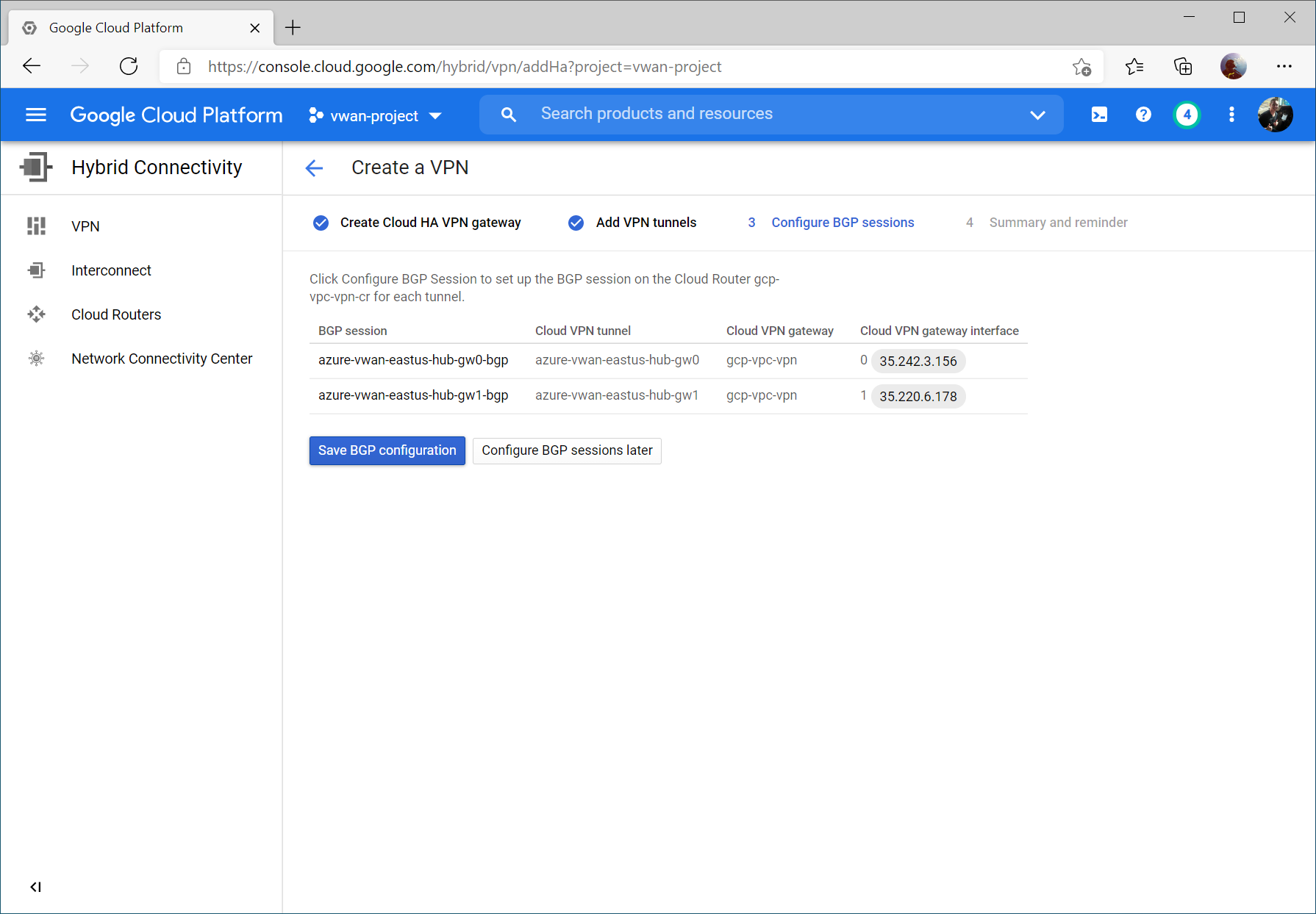
Click the Save BGP configuration button.
Configure Azure Virtual WAN VPN Site
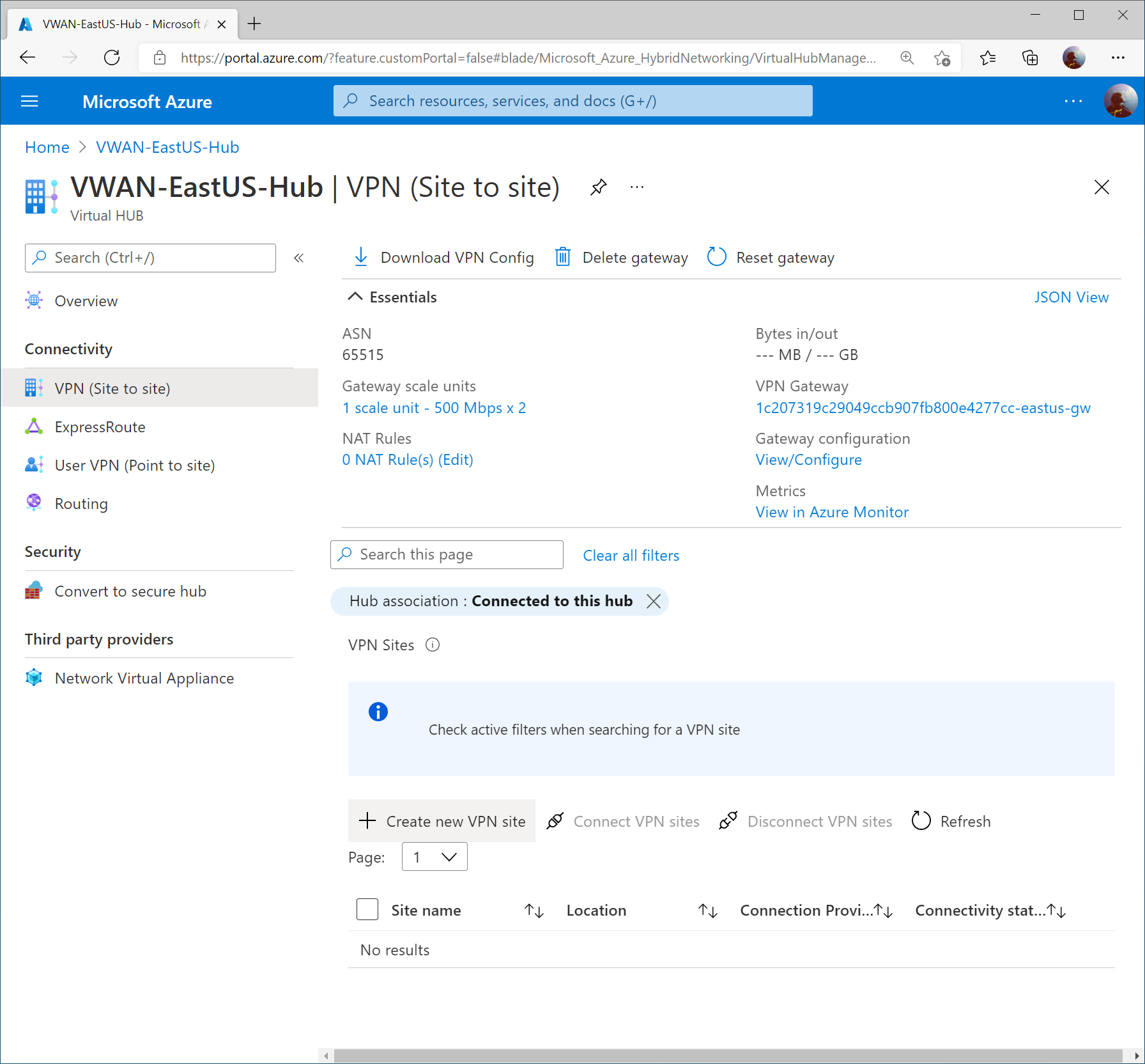
On the Virtual WAN hub, select VPN (Site to site) and click + Create new VPN site
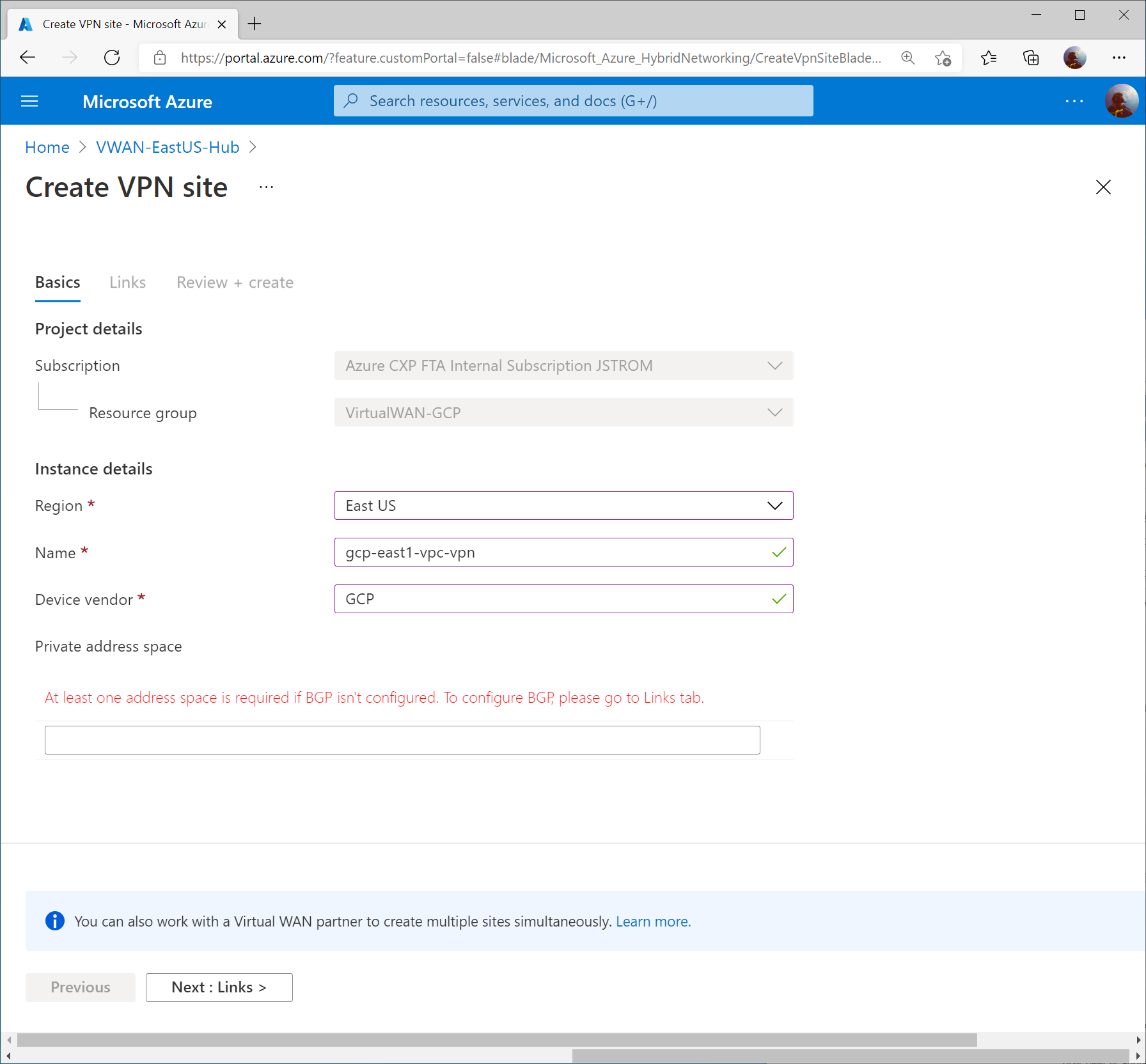
Specify a name for the VPN connection, enter GCP for vendor, and click Next : Links >
Specify the following values to define each VPN tunnel that should be created to connect to GCP’s VPN interfaces.
Note: I entered 1000 for the link speed as a placeholder, but that doesn’t mean the connection will be throttled down to 1Gbps.
First Link:
Link Name: gcp-east1-vpc-vpn-int0
Link Speed: 1000
Link provider name: GCP
Link IP address: <GCP VPN Interface 0 Public IP>
Link ASN: 64700
Second Link:
Link Name: gcp-east1-vpc-vpn-int1
Link Speed: 1000
Link provider name: GCP
Link IP address: <GCP VPN Interface 1 Public IP>
Link ASN: 64700
Click Create
Configure Virtual WAN VPN Connection
Once the Virtual WAN Hub has been created, click the Menu icon and select All services.
Search for Virtual WAN and select Virtual WANs.
Select your Virtual WAN resource.
Click on Hubs under Connectivity and select your Virtual WAN Hub.
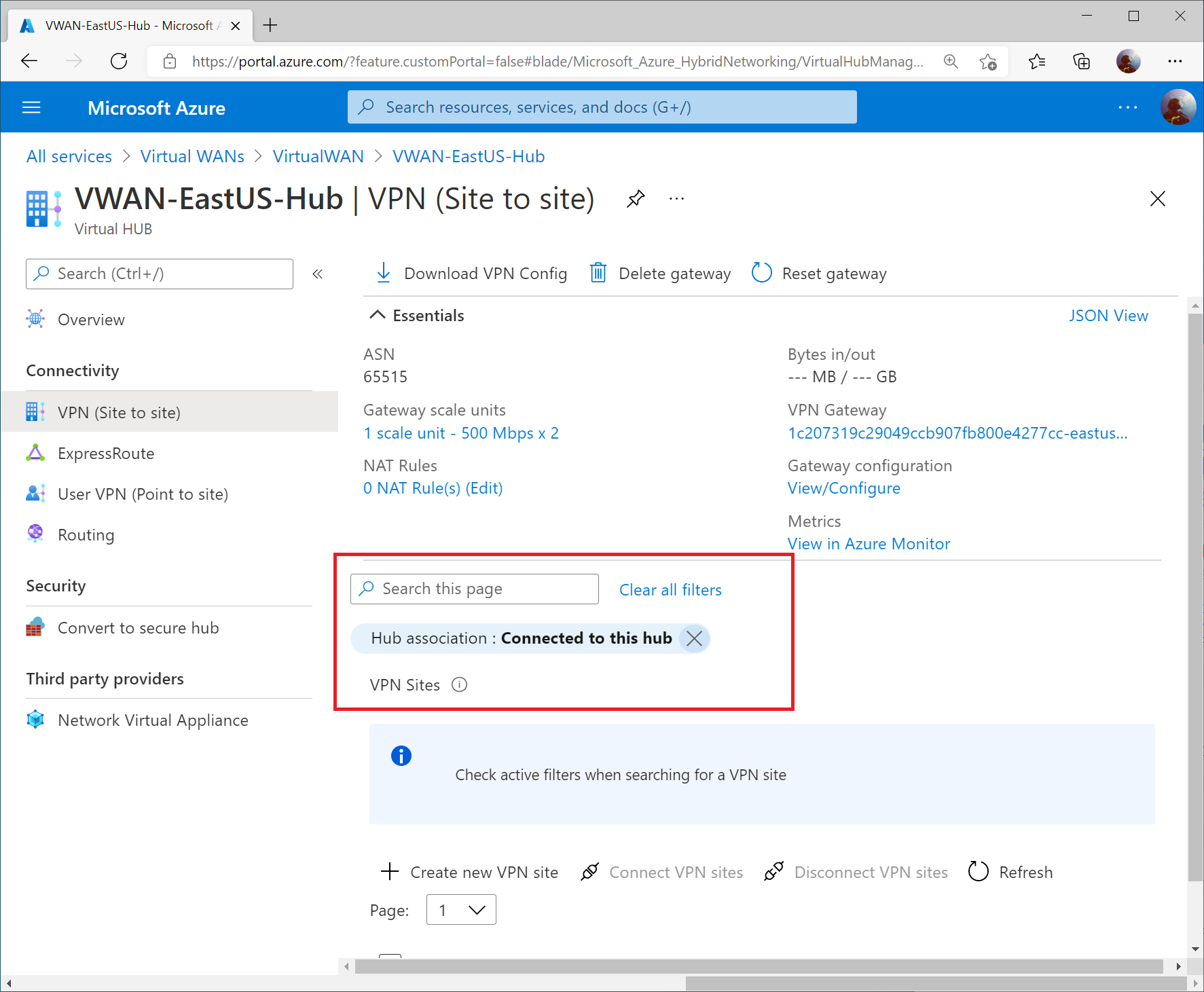
Select VPN (Site to Site) under Connectivity and then click on the X to remove the Hub association filter.
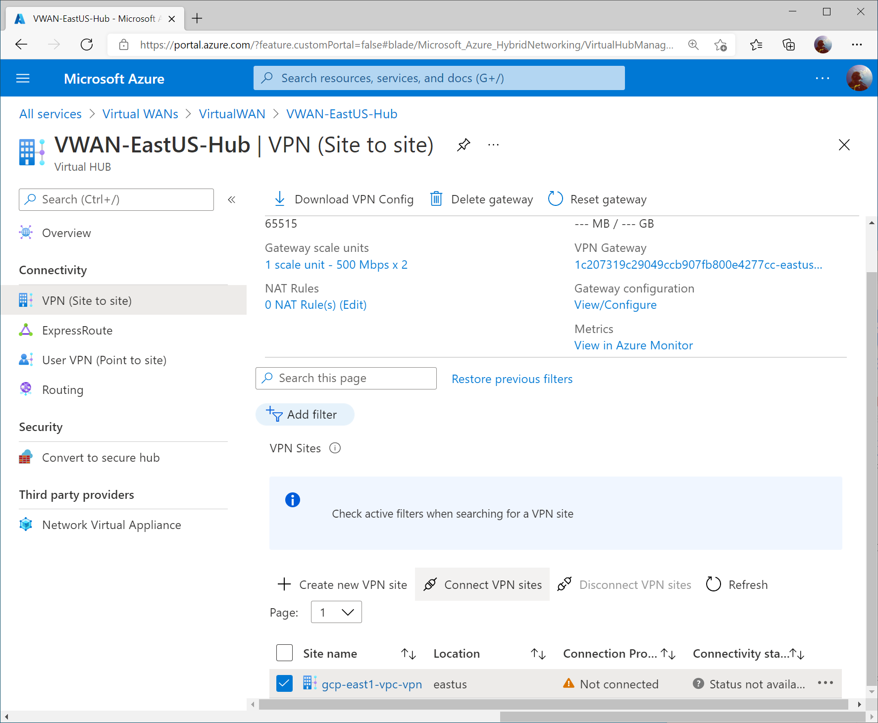
Check the box for your VPN site and click Connect VPN sites
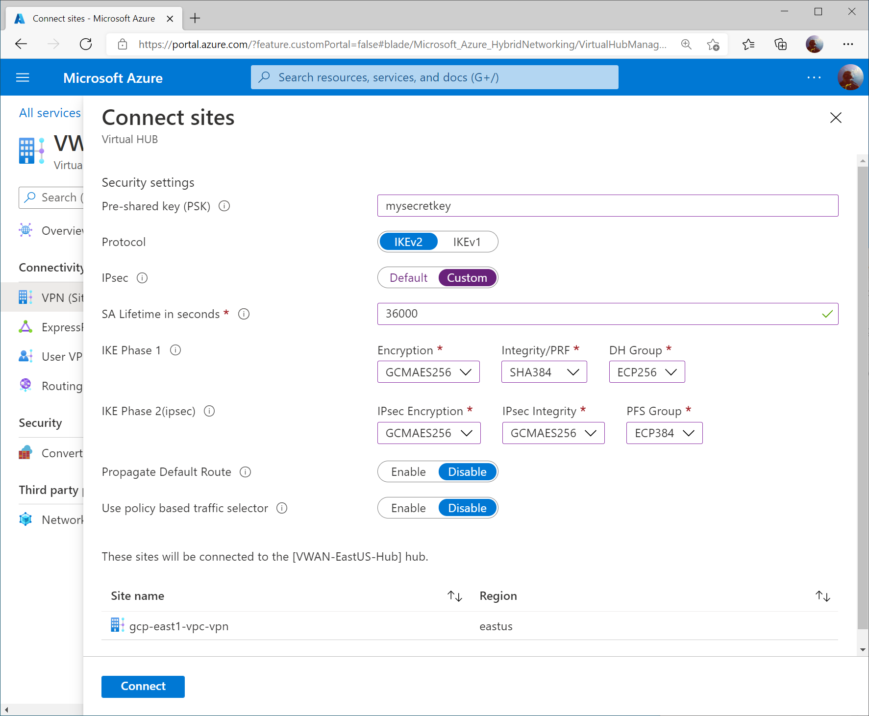
Specify the following information:
Pre-shared key (PSK): <use the same one you specified in GCP>
From the Azure Side, we will review three different areas to validate connectivity and propagation of routes via BGP.
Note: I connected a virtual network to the Virtual WAN Hub to show further configuration. In this case, you’ll see an additional IP address space of 10.51.0.0/16, which defines my connected VNet.
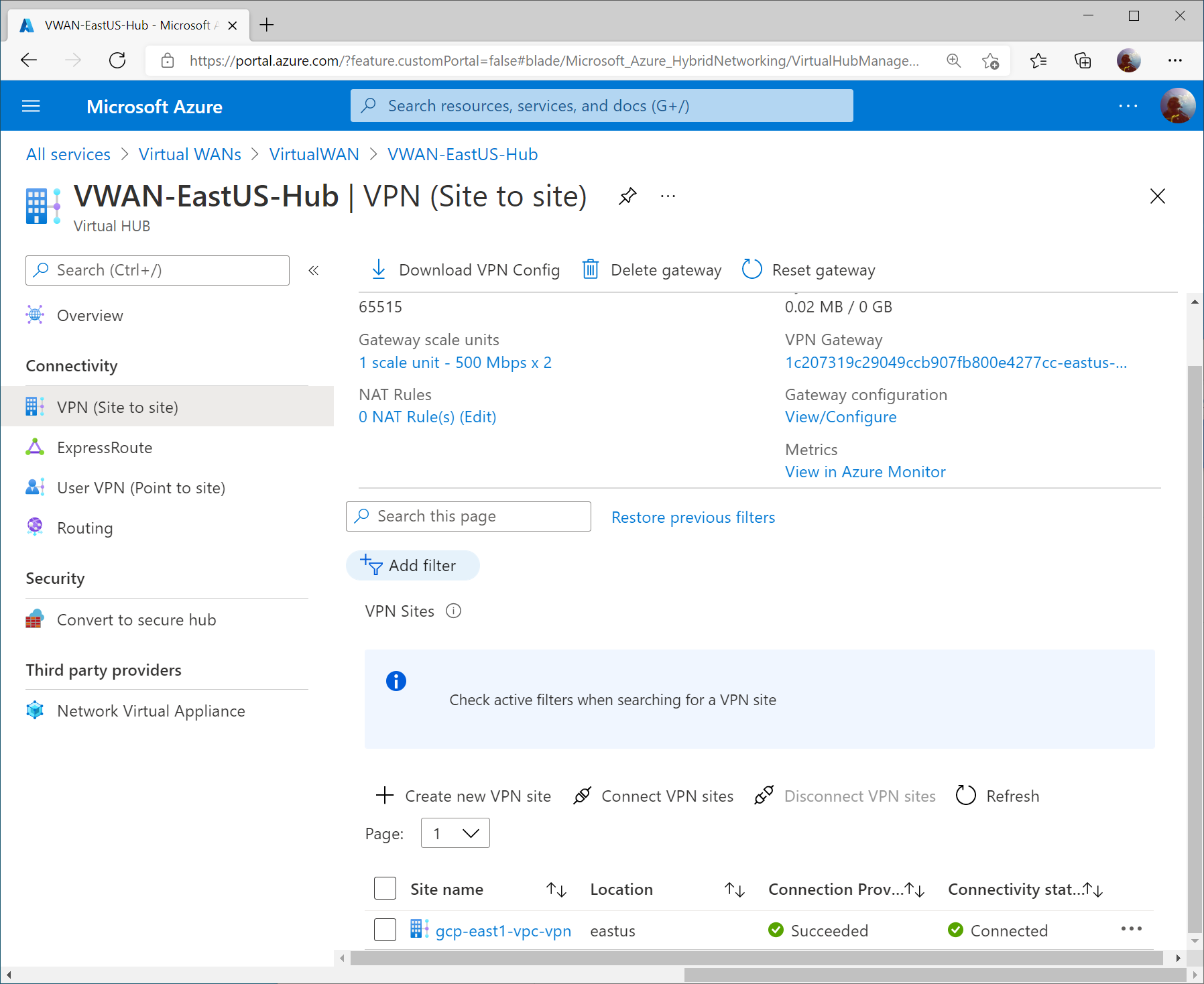
On the Azure Side, you should see the VPN Site’s Connectivity status change to Connected on the VPN (Site to site) blade of your Virtual WAN hub.
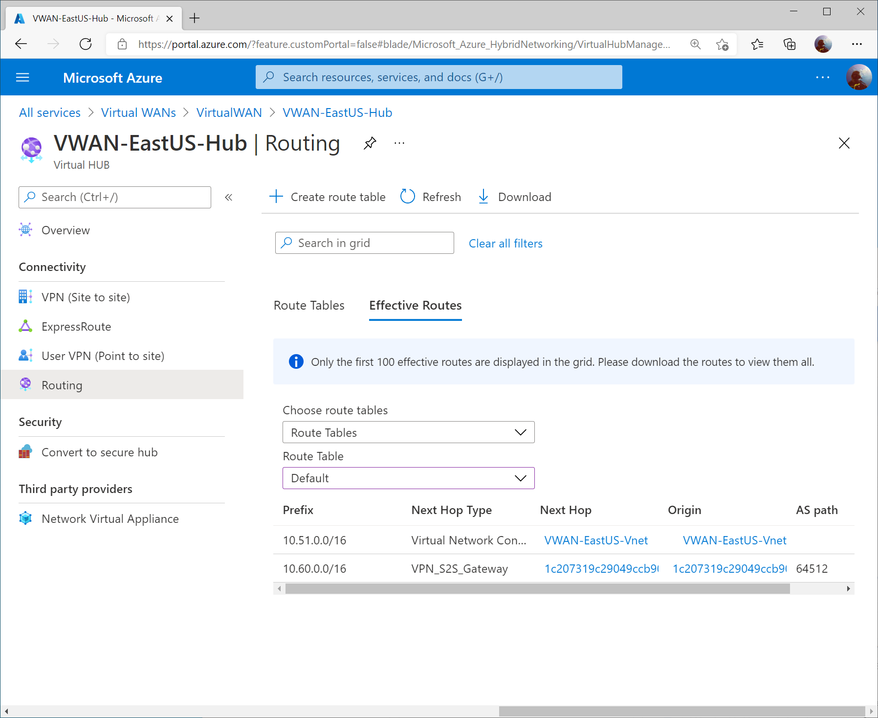
On the Routing blade, the Effective Routes will show you the learned VPC address space from GCP (10.60.0.0/16)
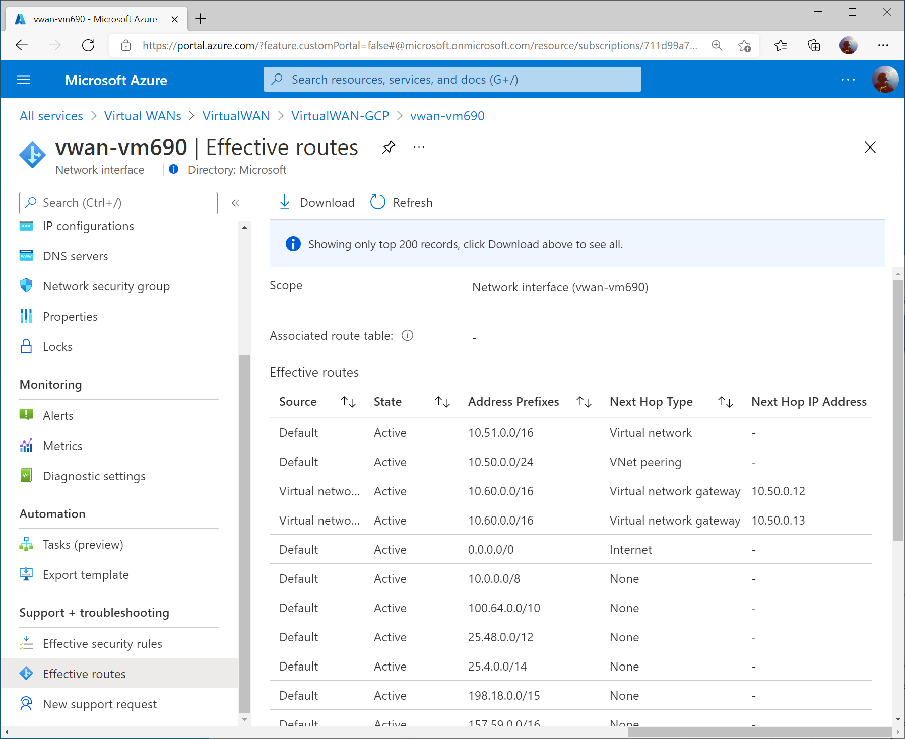
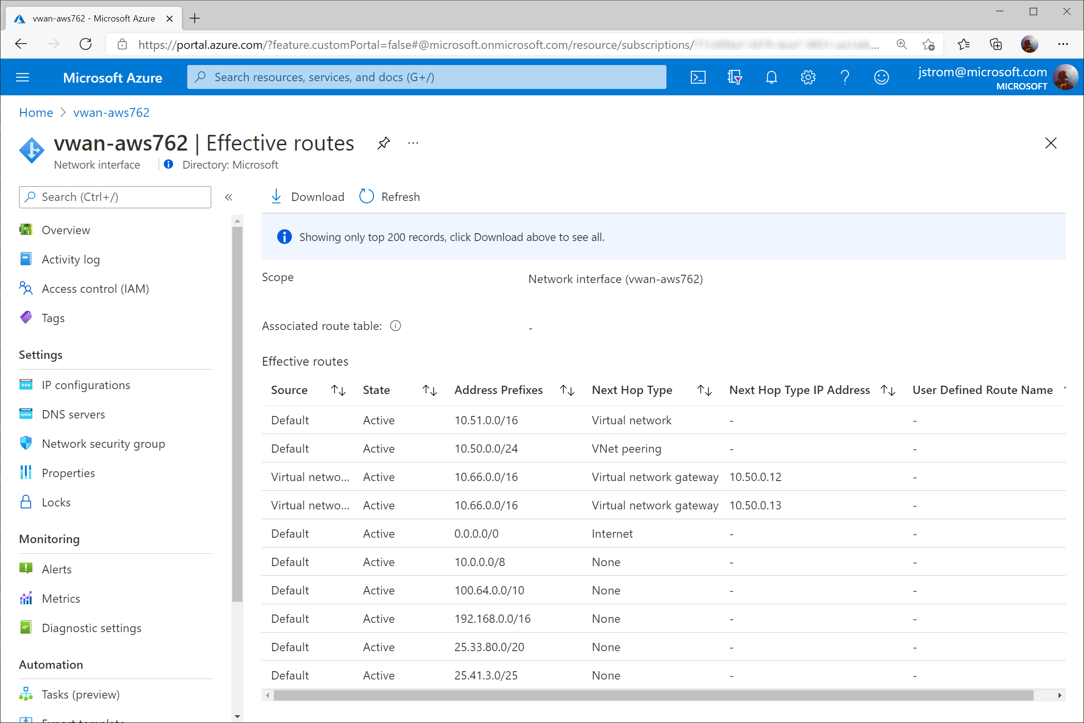
On a virtual machine in a connected VNet to the Virtual WAN Hub, you can pull the Effective Routes. Here I see the 10.60.0.0/16 route learned from both Instance 0 and Instance 1 gateways from the Virtual WAN Hub.
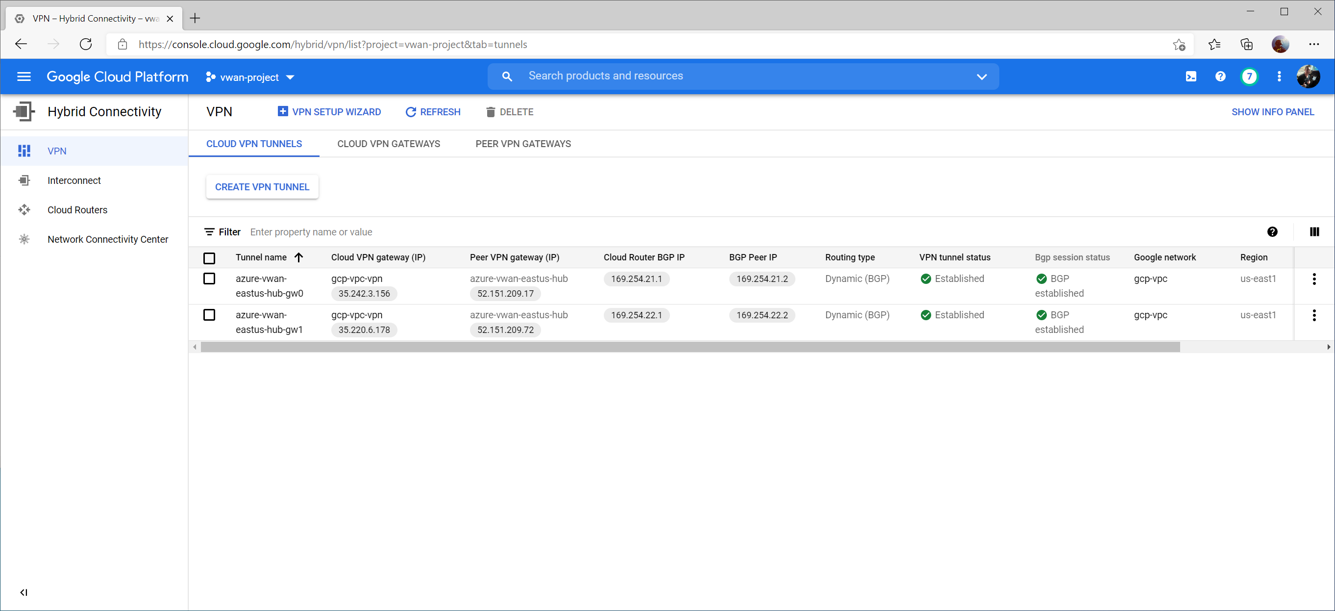
From the GCP Side, we can see the VPN tunnel status as well as Bgp session status now Established and Green on the Hybrid Connectivity -> VPN -> Cloud VPN Tunnels section.
If we switch over to Hybrid Connectivity -> Cloud Routers -> and select View on the logs column
Further, if creating a VM (instance) in GCP, you can view the Firewall and Route details to confirm you see the learned routes from the gateway (in our case, we see 10.51.0.0/16 and 10.50.0.0/24 learned from both BGP Peers):
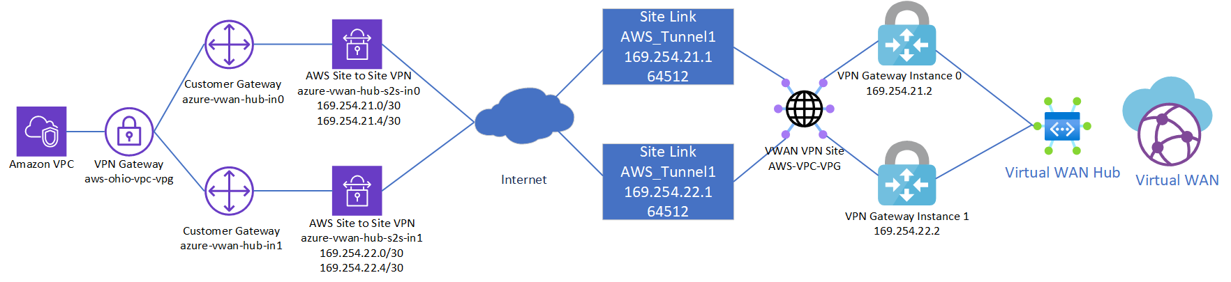
This is a quick reflection of the steps I took to establish two IPSec tunnels between AWS’ VPG and Azure’s Virtual WAN VPN Gateway, propagating routes dynamically via BPG and ensuring High Availability. The design itself is a bit interesting since AWS and Azure differ on how connections are established to remote peers. When everything is said and done, you’ll end up with a diagram that conceptually looks something like this:
Note: It is recommended to start with the Virtual WAN side first since you cannot modify the IP address of a Customer Gateway in AWS
Create Azure Virtual WAN and Virtual WAN Hub
On the Azure side, first we need to create a Virtual WAN resource and a Virtual WAN Hub, which will contain our VPN Gateway. If you have already created these, you can skip to the next session.
First, click the “Hamburger” icon and select Create a resource
Search for Virtual WAN and select it from the list in the marketplace.
Select Create
Specify the resource group and region you wish to deploy the Virtual WAN resource to. Specify a name for your Virtual WAN resource and click Review + Create
Click Create to start provisioning the Virtual WAN resource.
Once the resource is created, click Go to resource to navigate to your Virtual WAN resource.
On the Virtual WAN resource, select New Hub from the top menu.
Specify the name of the Hub and an address space that can be used for all the networking components Virtual WAN will deploy into the Virtual Hub. Click Next : Site to Site >
On the Site to Site tab, toggle Yes that you want to provision a VPN Gateway, and specify the scale units you need. Click the Review + create button when done.
Click the Create button to start provisioning the Hub and VPN Gateway. Please note this can take up to 30 minutes to complete.
Configure customer BGP IP Address for Virtual WAN VPN Gateway Instances
Once provisioning is completed, navigate back to the Virtual WAN resource. You can do this by clicking the “Hamburger” icon and searching for Virtual WAN
Select your Virtual WAN resource.
You should now see your Virtual WAN Hub resource you provisioned. Select the Virtual WAN Hub.
On the Virtual WAN Hub, click on the View/Configure link.
On the View/Configure Gateway Configuration blade, specify 169.254.21.2 as the Custom BGP IP address for Instance 0 and 169.254.22.2 as the Custom BGP IP address for Instance 1. Notate the Public IP address uses for Instance 0 and 1 and then click Edit and Confirm to apply the changes.
Create Virtual WAN VPN Site
On the Virtual WAN Hub, click Create new VPN Site
Specify a name for your VPN Site to define the connection connecting to AWS. Click Next : Links >
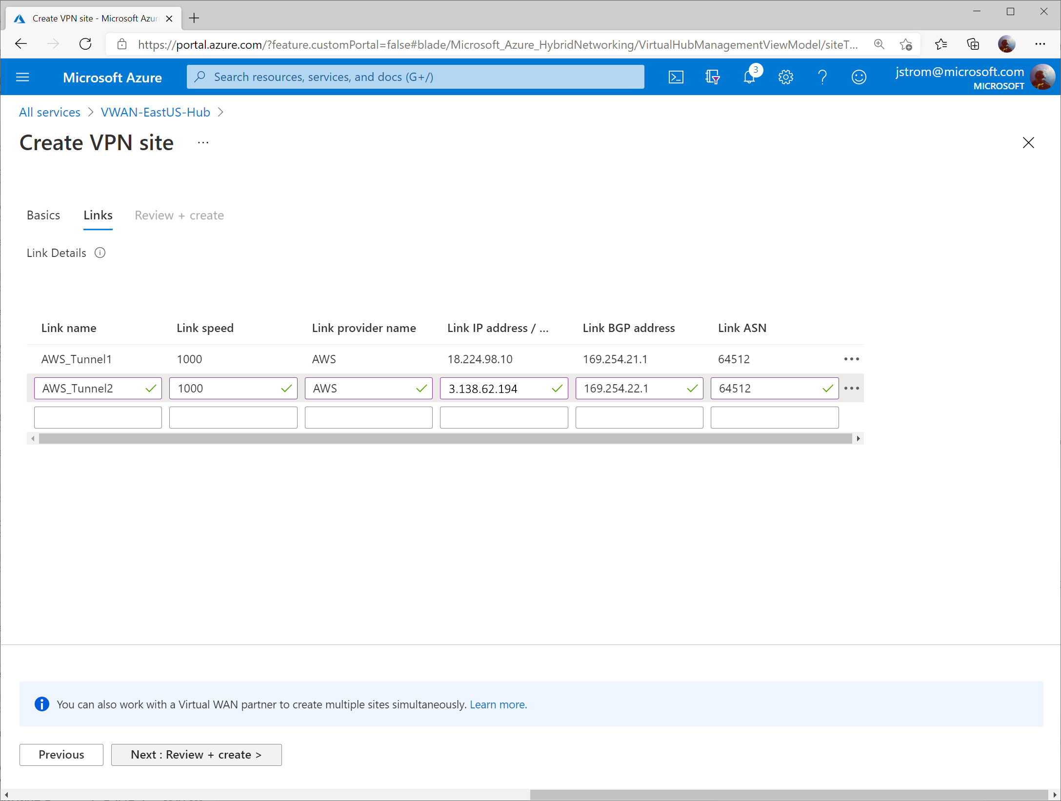
On the Links tab, add two entries with the following values (to tell VWAN how to connect to each of the AWS Site-to-Site connections). Note: this is very similar to AWS’ Customer Gateway section.
Link 1:
Link Name; AWS_Tunnel1
Link Speed: 1000
Link Provider Name: AWS
Link IP address: 1.1.1.1 (this is a placeholder value until we configure the AWS side)
Link BGP address: 169.254.21.1
Link ASN: 64512
Link 2:
Link Name; AWS_Tunnel2
Link Speed: 1000
Link Provider Name: AWS
Link IP address: 1.1.1.2 (this is placeholder value until we configure the AWS side)
Link BGP address: 169.254.22.1
Link ASN: 64512
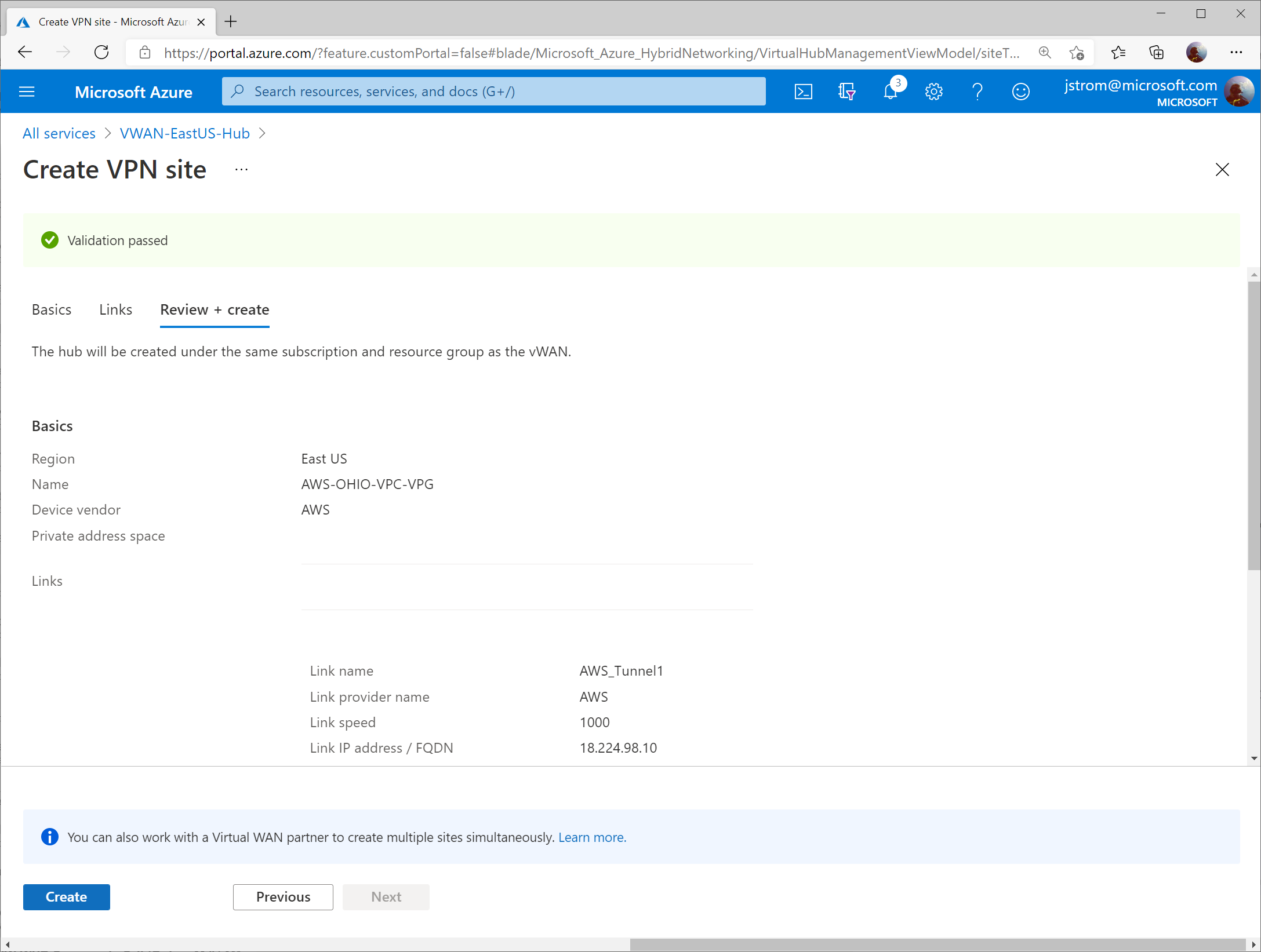
Click Next: Review + Create >
Click Create
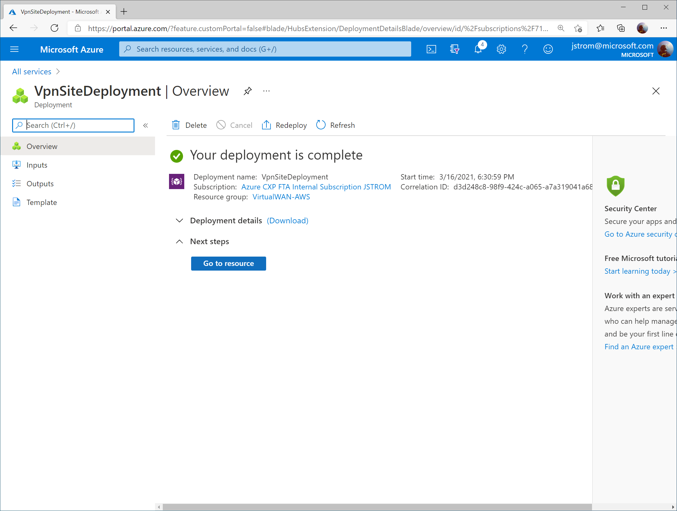
Click Go to resource once the links have finished being created.
Configure Phase 1/2 Proposals
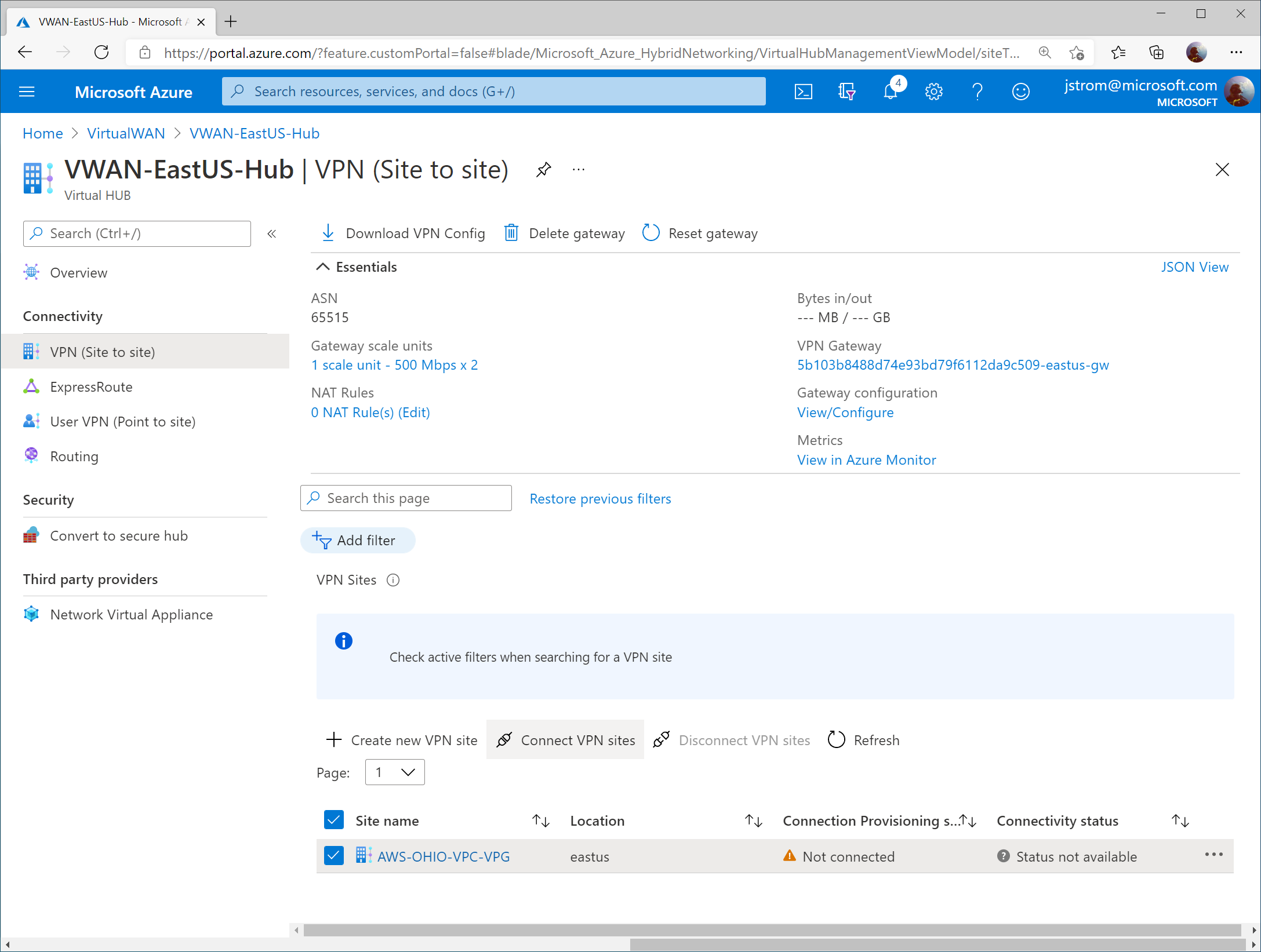
Select your Virtual WAN hub on the Virtual WAN Overview blade.
Check the box for the new VPN Site Name and click the Connect VPN sites button
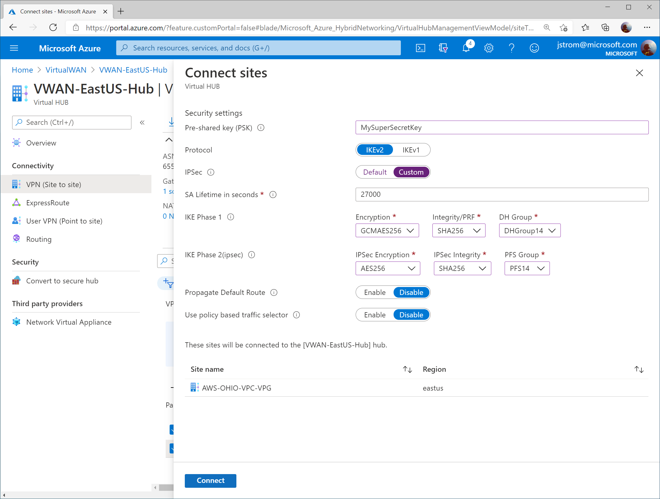
Specify the following configuration:
Pre-shared key (PSK): YourSecretKeyWithNumb3rs
Must be a 8-64 character string with alphanumeric, underscore(_), and dot(.). It cannot start with 0.
Protocol: IKEv2
IPSec: Custom
IKE Phase 1:
Encryption: GCMAES256
GCM algorithm is more efficient and can improve throughput on the Azure Gateways
Integrity/PRF: SHA256
DH Group: DHGroup14
IKE Phase 2 (ipsec):
IPSec Encryption: AES256
AWS does not support GCM algorithm for IPSec integrity at time of writing this, but if it is available, you may want to opt for that
IPSec Integrity: SHA256
PFS Group: PFS14
Click Connect
Configure AWS
Prerequisites
This guide assumes you have a VPC already (in my case, mine is called AWS-OHIO-VPC), a corresponding set of subnets for your servers, and a route table associated to your VPC.
Note: An AWS VPC is the equivalent of a VNet in Azure. One thing that is different between AWS and Azure is that in AWS you do not need to specify a subnet for your Gateways (i.e. “GatewaySubnet”).
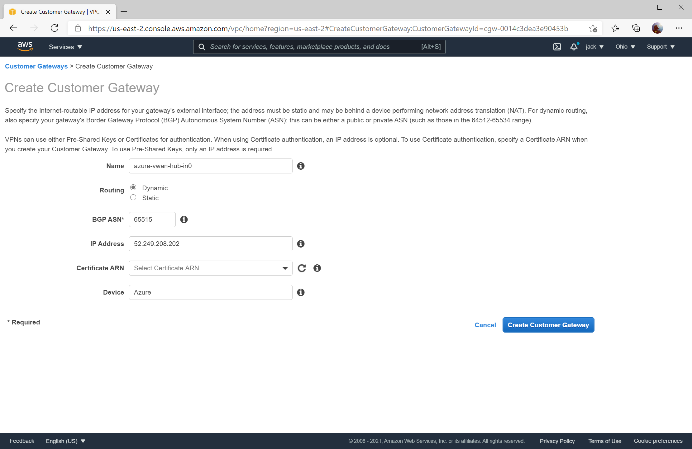
Create the Customer Gateways
Customer Gateways in AWS are the equivalent of a local network gateway that you’d associate to a connection for a traditional VPN Gateway in Azure. It is also the equivalent of a defined Site Link for Azure’s Virtual WAN VPN configuration.
In this section, you will need to create two Customer Gateways. Specify the corresponding instance value obtained from the Configure Customer BPG IP address section. When creating the Customer Gateways ensure Dynamic routing is enabled and the BGP ASN is specified as 65515.
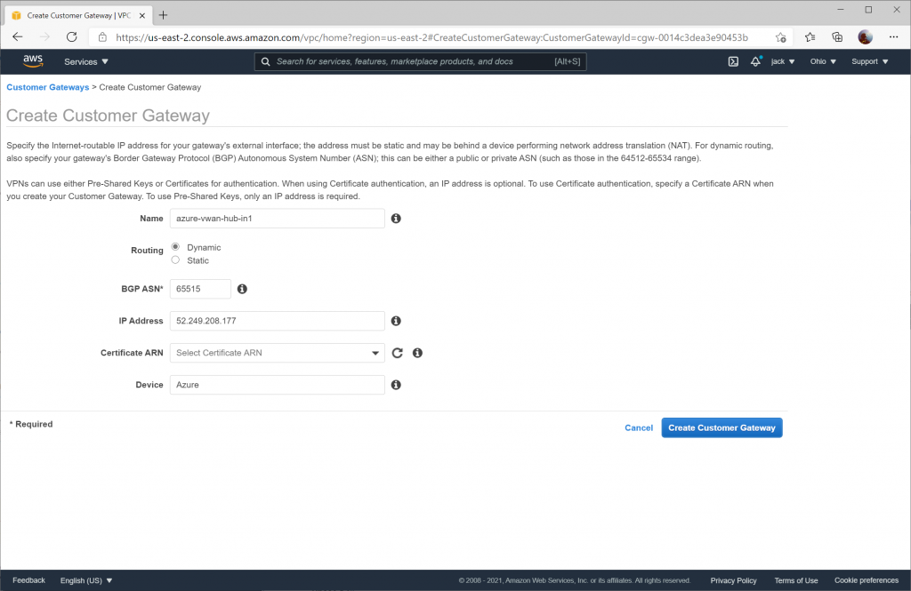
Configuration for the second Customer Gateway using the Instance 1 Gateway Public IP address.
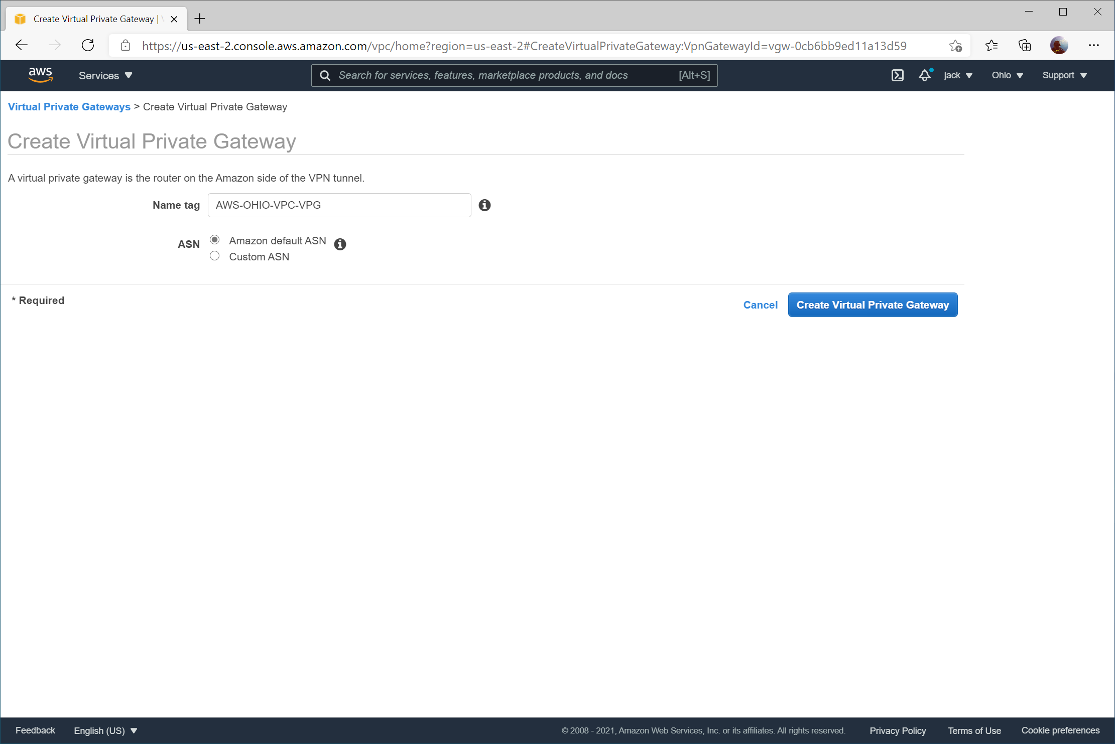
Create a Virtual Private Gateway
Next we need to create an AWS Virtual Private Gateway. This is the equivalent of Azure’s VPN Gateway.
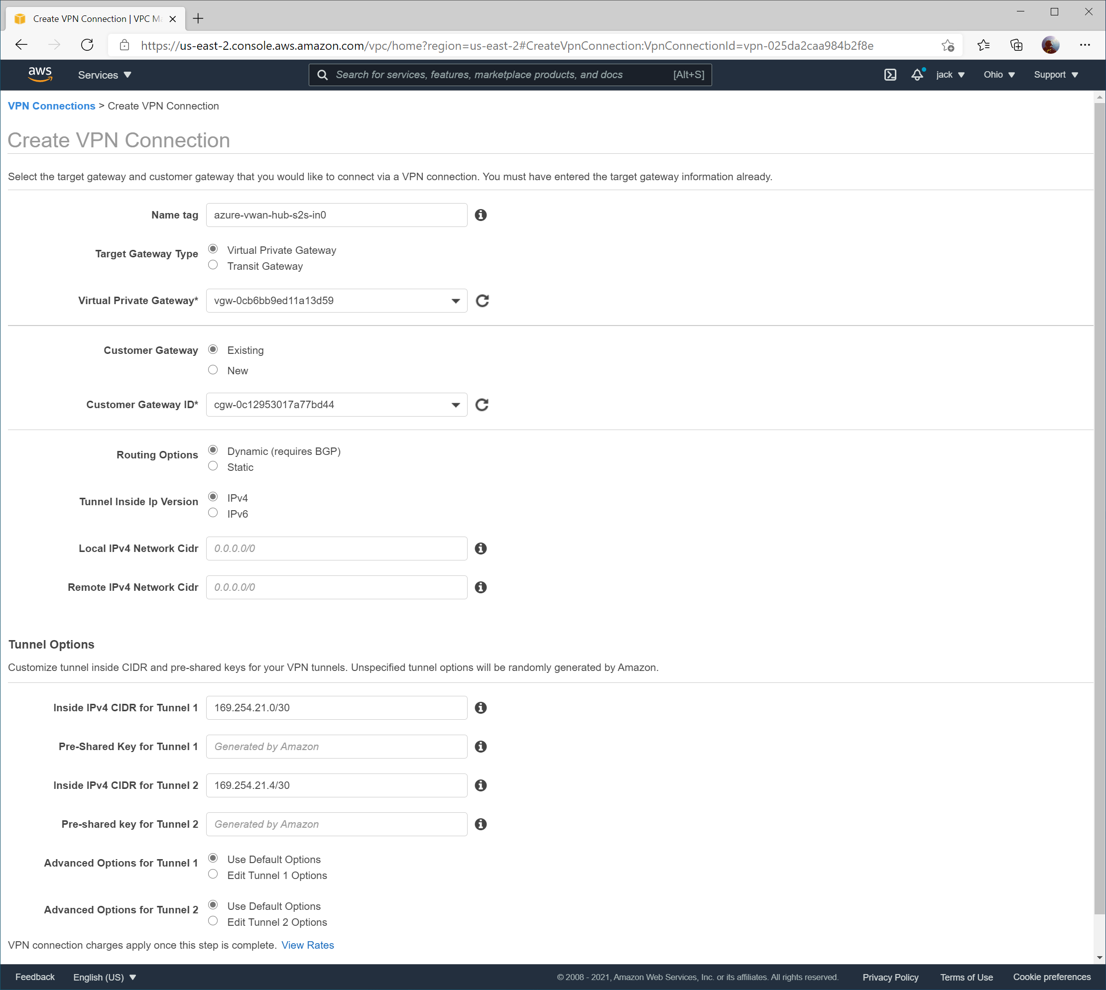
Create VPN Connections
We need to create two VPN Connections, each VPN Connection linked to its corresponding Customer Gateway and VPC.
On the Inside IPv4 CIDR for Tunnel 1 on the first VPN Connection, ensure you use 169.254.21.0/30 as the BGP Peer addresses and 169.254.21.4/30 for the second tunnel. Due to the way that the VPN Connection works, we are using a placeholder value of 169.254.21.4/30 tunnel, which will never be used in practice since we cannot point it to leverage Azure’s secondary VPN Gateway instance. This value must be specified as if we define the secondary BGP Peer address that will be created for the secondary instance in VWAN, you will receive an error that overlapping address space exists between this VPN Connection and the secondary VPN connection we create in AWS. Add the pre-shared key value you specified in Azure during this time as well.
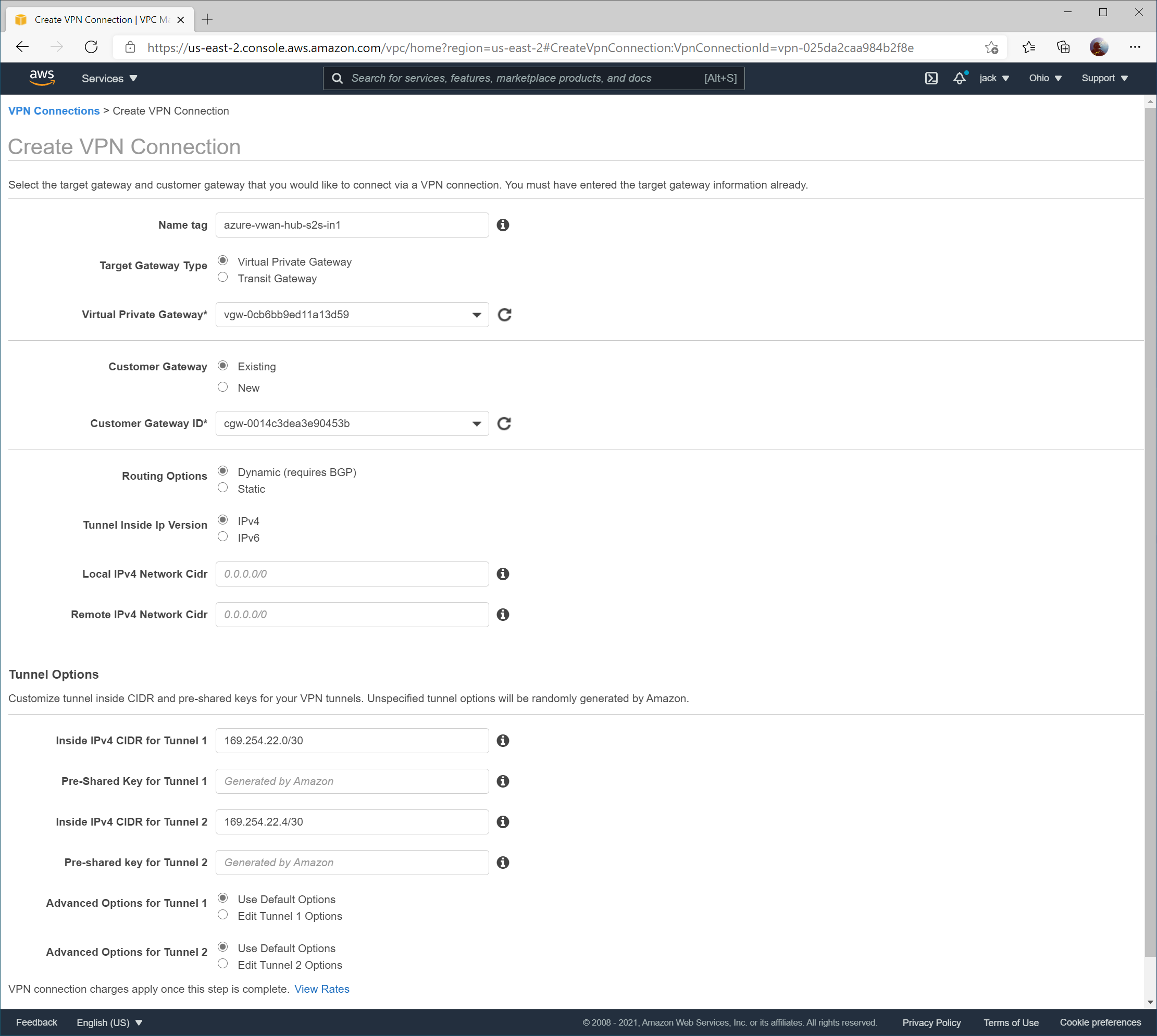
When creating the second VPN connection, ensure 169.254.22.0/30 is specified for Inside IPv4 CIDR for Tunnel 1 and 169.254.22.4/30 is specified for Inside IPv4 CIDR for Tunnel 2 (which is again a placeholder value that won’t be used).
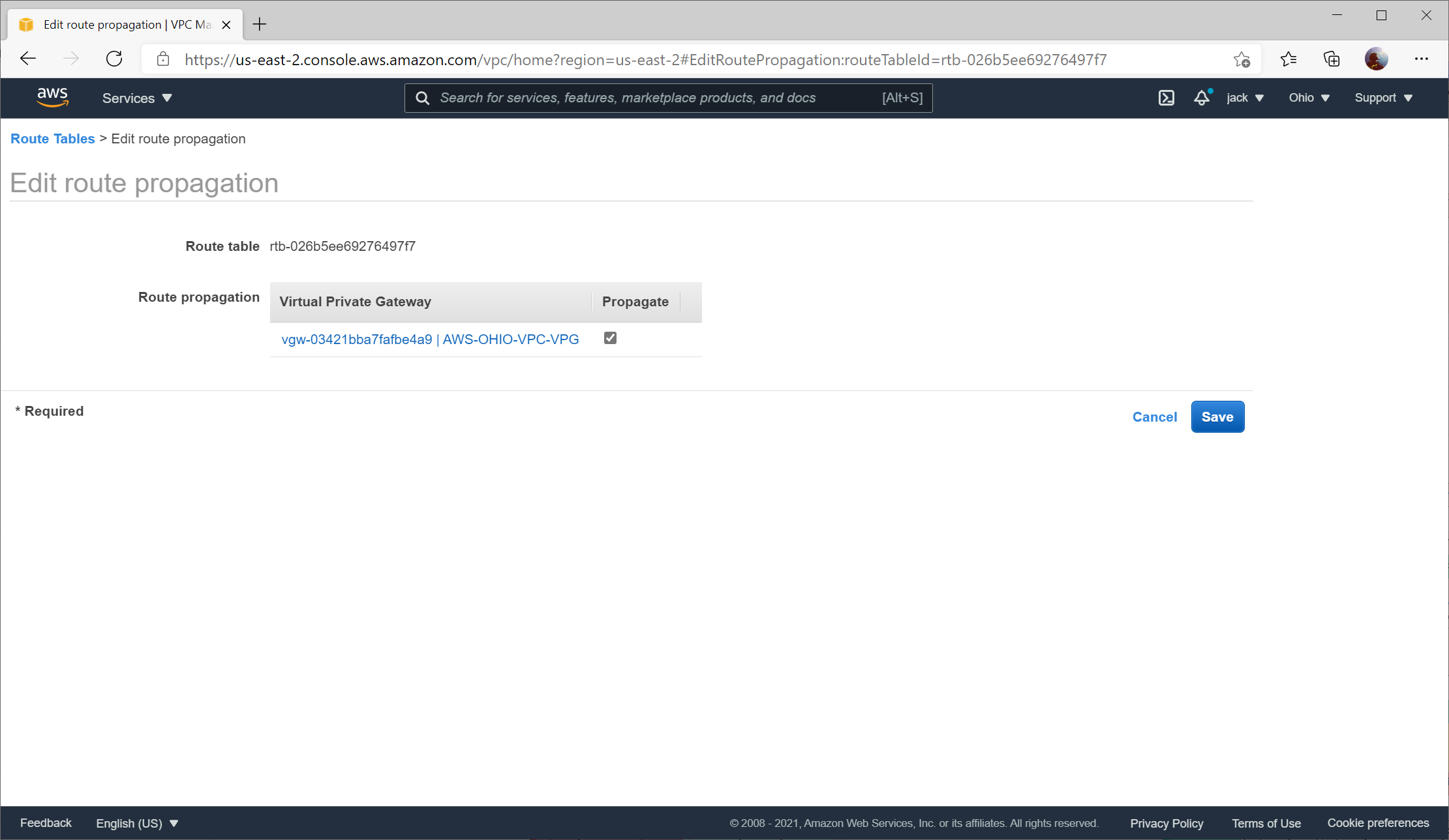
Configure Route Table to Propagate Routes
To allow the learned routes from BGP propagate to the VPC, you need to enable route propagation on your Route Table.
Navigate to Route Tables and select your Route Table and click the Route Propagation tab and select Edit route propagation
Check the Propagate box and click Save
Update Azure
Update Azure Site Link IP addresses
As per the Configure Phase 1/2 Proposals section for Azure Virtual WAN, you specified 1.1.1.1 and 1.1.1.2 as a placeholder value for the Public IP addresses of the AWS VPN Gateway instances. We will need to update these addresses with the proper values.
Naviate to your Virtual WAN instance and select your Virtual WAN hub
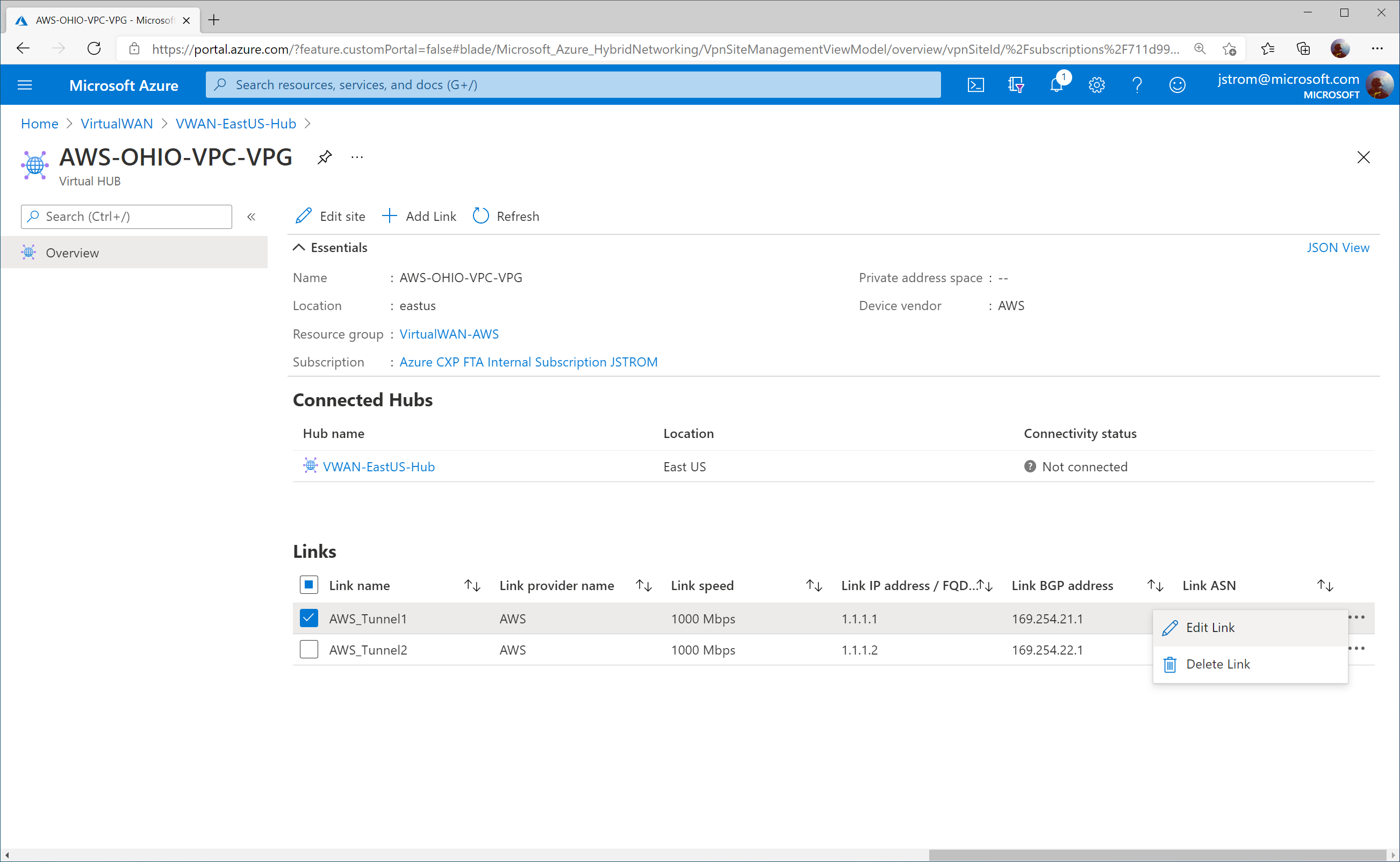
Select VPN (Site to site) and choose click on the Site name you created
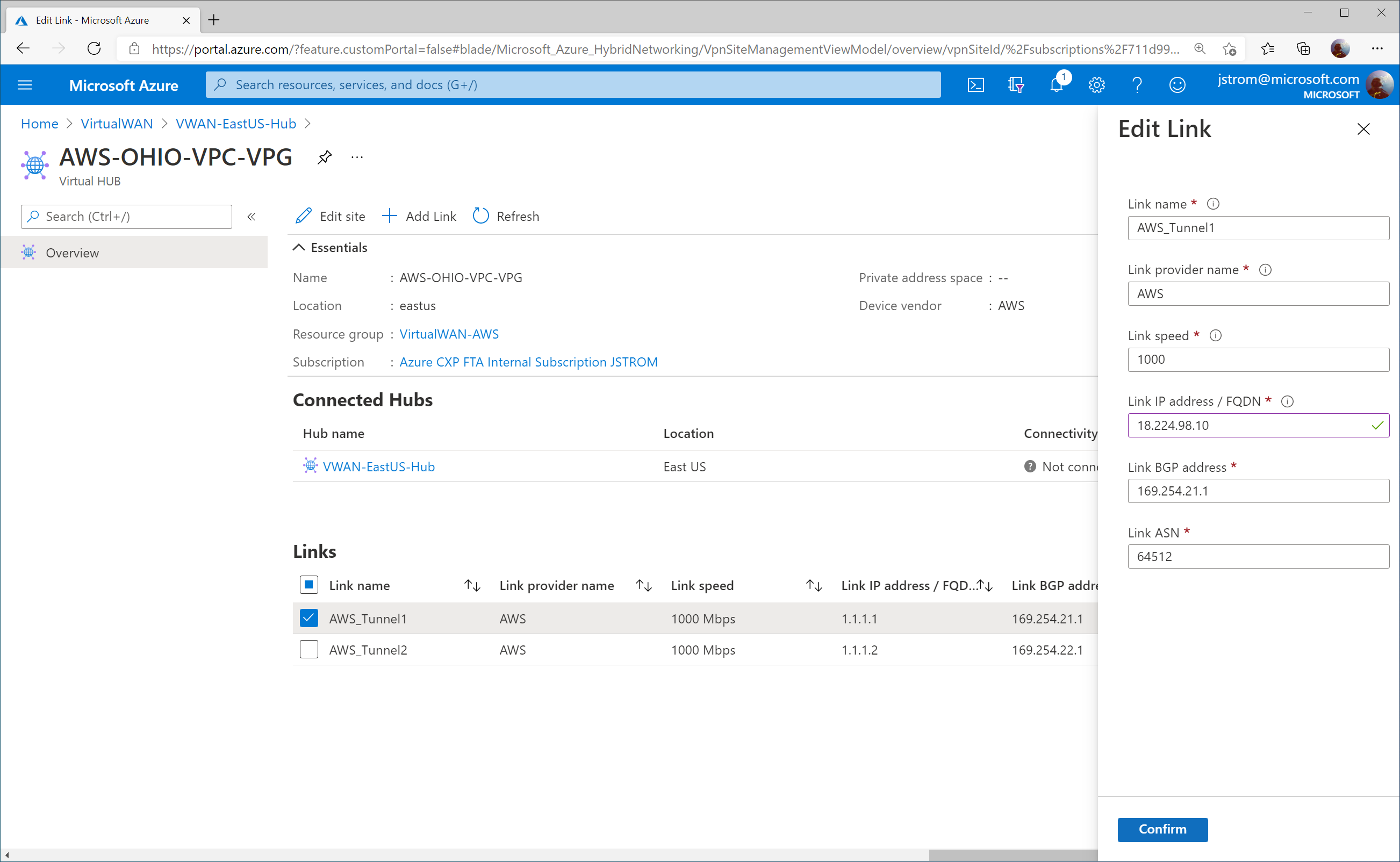
Click on the three dots (ellipsis) for AWS_Tunnel1 and click Edit Link.
Specify the proper IP address for Tunnel 1 on AWS Site-to-Site connection 1. Click Confirm.
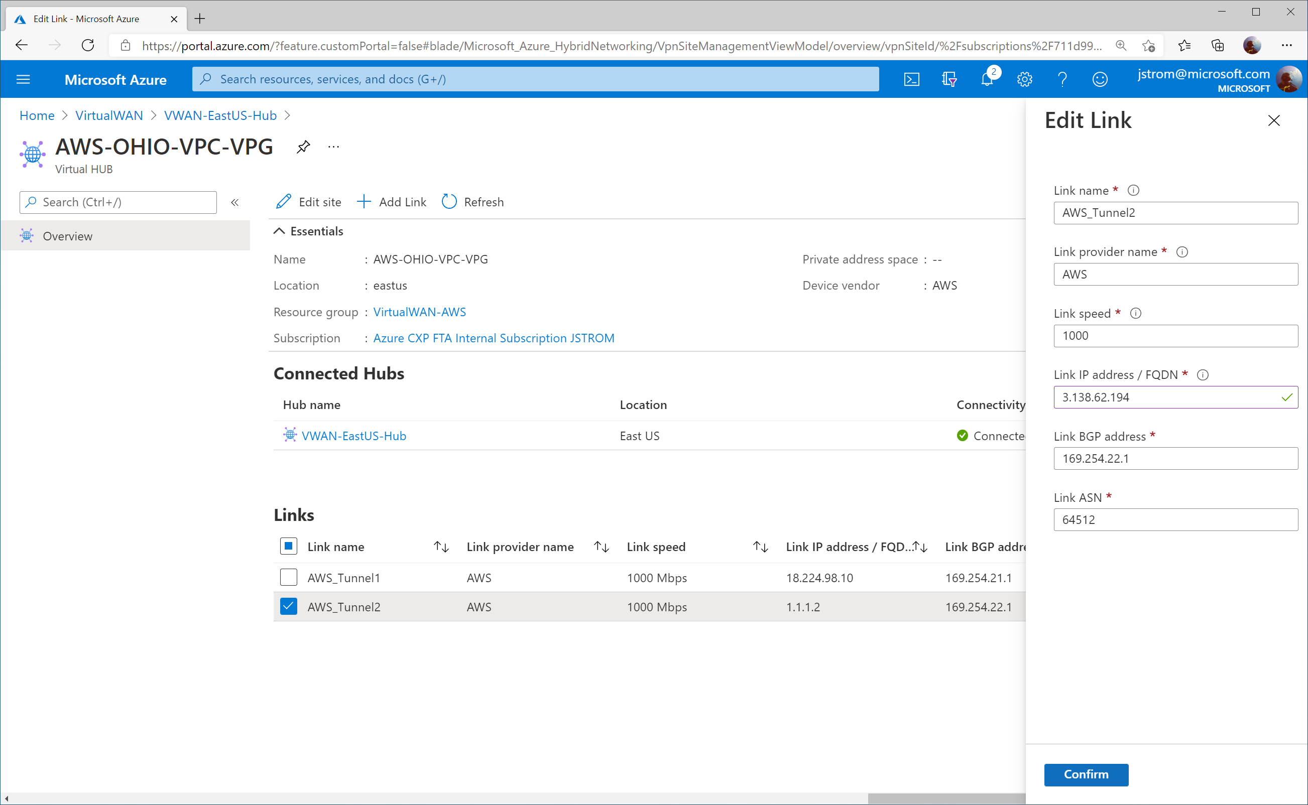
Click on the three dots (ellipsis) for AWS_Tunnel2 and click Edit Link.
Specify the proper IP address for Tunnel 1 on AWS Site-to-Site connection 2. Click Confirm.
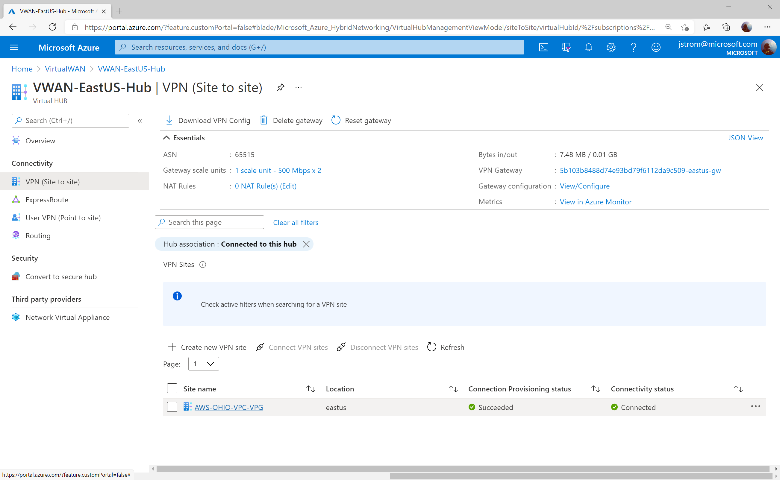
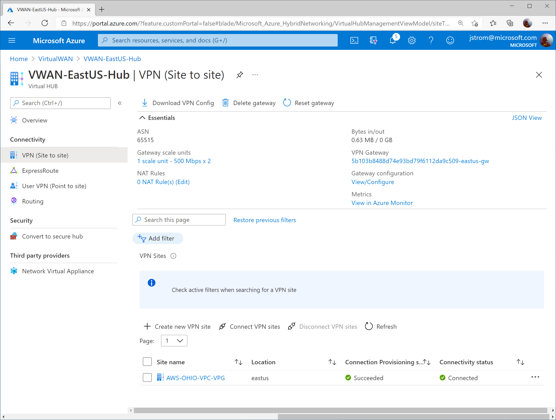
Verify connectivity
On the Azure Side, you should see the VPN Site’s Connectivity status change to Connected
You can also select a Virtual Machine that may have it’s virtual network attached to the VWAN Hub and validate you see learned routes from the VWAN Hub (and AWS) propagated into the VNet.
Tip: You can see the same route twice as we have both VPN Gateway instance BGP Peers actively connected to AWS. In the event you lose a peer, you would only see one route to one gateway listed.
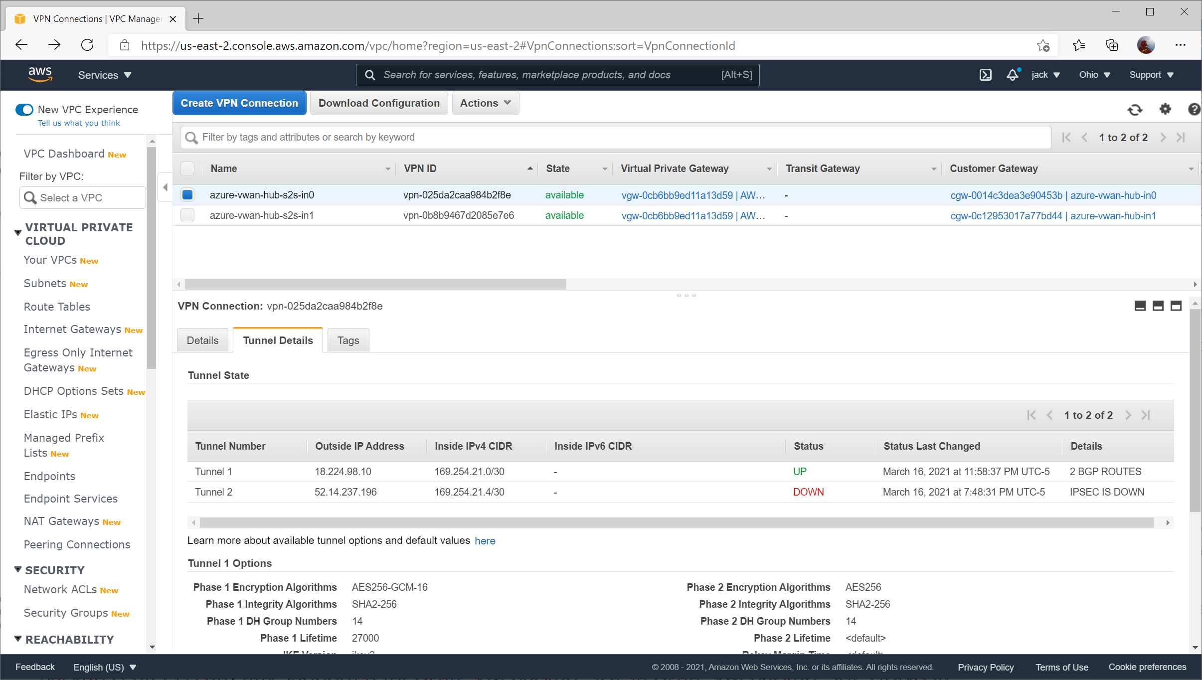
On the AWS side, you can validate for each Site to Site VPN connection that you see Tunnel 1‘s status as UP and Tunnel 2‘s status as DOWN (remember, Tunnel 2 will always be listed as down because a fictitious BGP is specified).
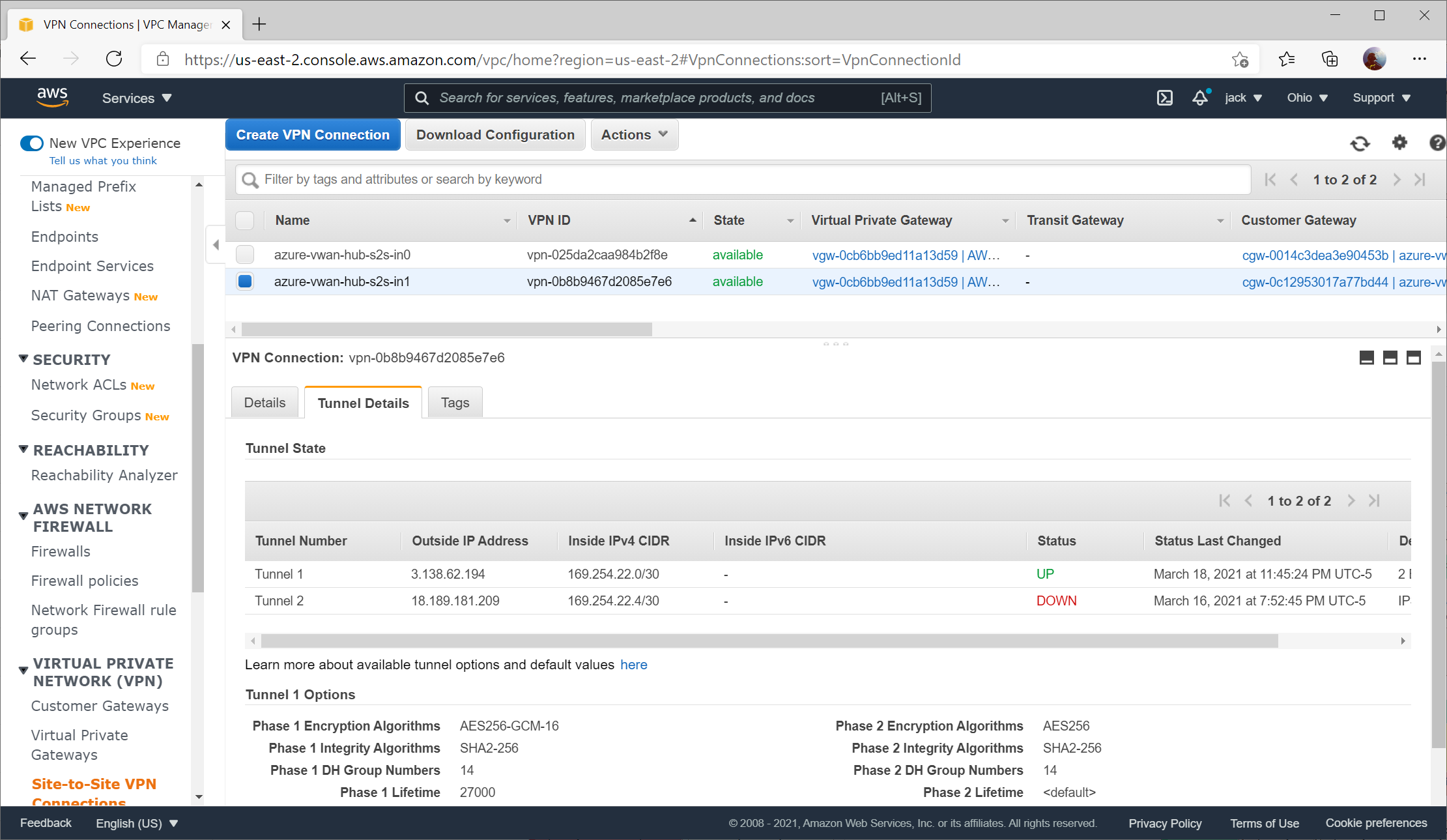
Here you can see the secondary Site-to-Site connection with the same status: UP for Tunnel 1, DOWN for Tunnel 2
In Home Assistant v2021.2, Home Assistant announced the Z-Wave integration as deprecated in favor of a new integration called Z-Wave JS. In Home Assistant v2021.3, many fixes were implemented, with the notable limitation of Door Sensors being removed.
More and more people were concerned about the future of Z-Wave with Home Assistant; meanwhile the Z-Wave JS project was rapidly growing and gathering a large community around it. Long story short: Home Assistant and Z-Wave JS teamed up! And a lot of contributors jumped on the train!
This new integration is based on the same base principles as the OpenZWave integration: It is decoupled from Home Assistant. Instead of MQTT, the Z-Wave JS integration uses a WebSocket connection to a Z-Wave JS server.
This means, in order to use this new integration, you’ll need to run the Z-Wave JS server that sits in between your Z-Wave USB stick and Home Assistant. There are multiple options available for running the Z-Wave JS server, via Docker or manually, and there is also a Home Assistant add-on available.
So how do I upgrade?
This article reflects the steps I took to update my Z-Wave implementation.
Ensure you are running Home Assistant v2021.3.2 or greater
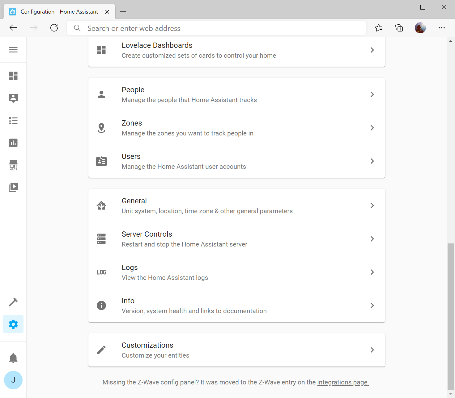
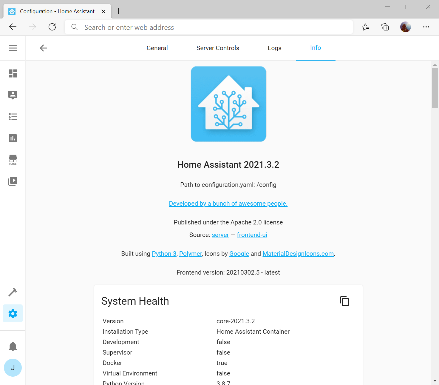
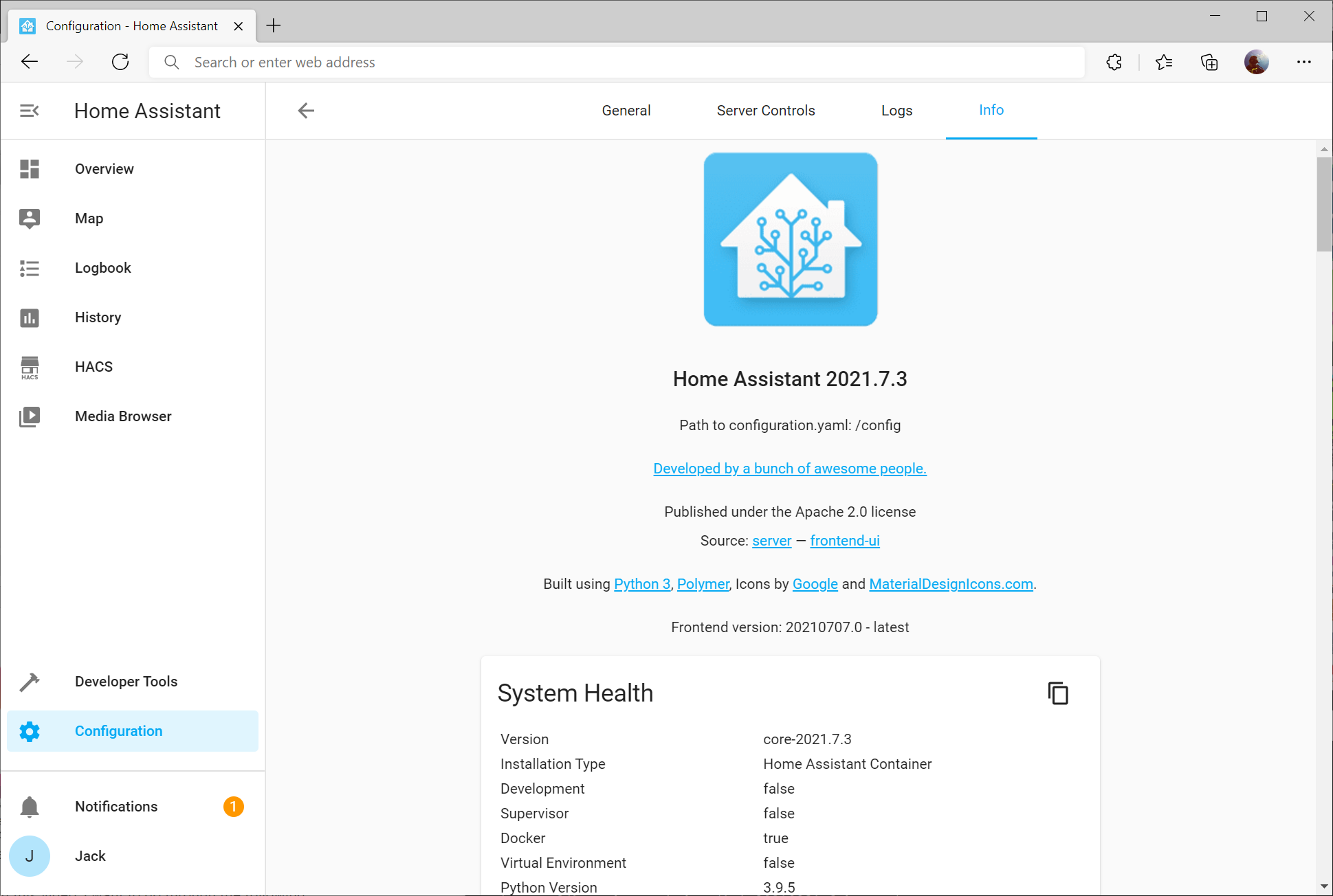
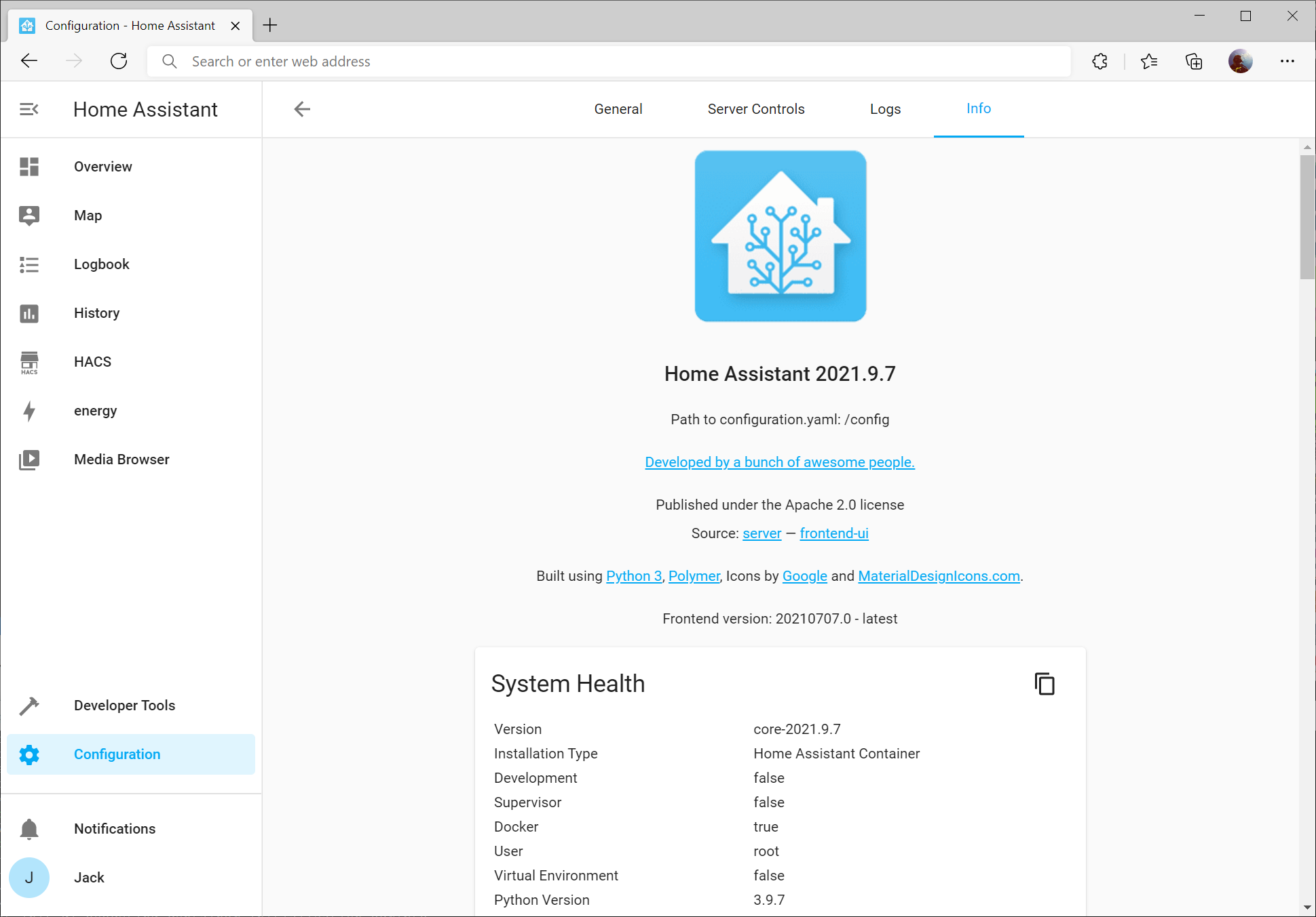
This will ensure you have support for most all sensors. You can find your Home Assistant version by selecting the Configuration gear on the left menu, and then selecting Info
Here you should see the version of Home Assistant (in my case 2021.3.2)
It’s rather critical to create a backup, especially in this case if you need to roll back to the older OpenZWave integration if you find many of your devices not being compatible. One downside in not using Home Assistant’s OS is you don’t have the “Supervisor” option to create a full backup.
Execute the following commands against your machine:
sudo sh -c 'apt update && apt upgrade'
Make sure you restart your machine to ensure your kernel updates to the latest version:
sudo shutdown -r -t now
Document Z-Wave entity IDs
The easiest way to do this is to navigate to Developer Tools (hammer icon on the left menu) and then type node_id into the Attributes column’s filter.
In this case, you’ll want to write down the node_id and the name of the entity it maps to. If you want to do this quickly, you can single click on the table, press Control + A to select all contents, or cmd+a on a Mac, and copy the contents into Word or Excel (Excel works remarkably well).
Document & Comment Z-Wave Stick Hardware ID and Network Key
SSH to your server and find your configuration.yaml file (if using my tutorial it should be /home/docker/home-assistant/configuration.yaml). Open the file in vi
sudo vi configuration.yaml
Find the section of code labeled zwave: and copy the information (we’ll need it later) as well as comment out the following lines like so:
Type :wq to write the changes to the file and quit vi
Uninstall Z-Wave integration
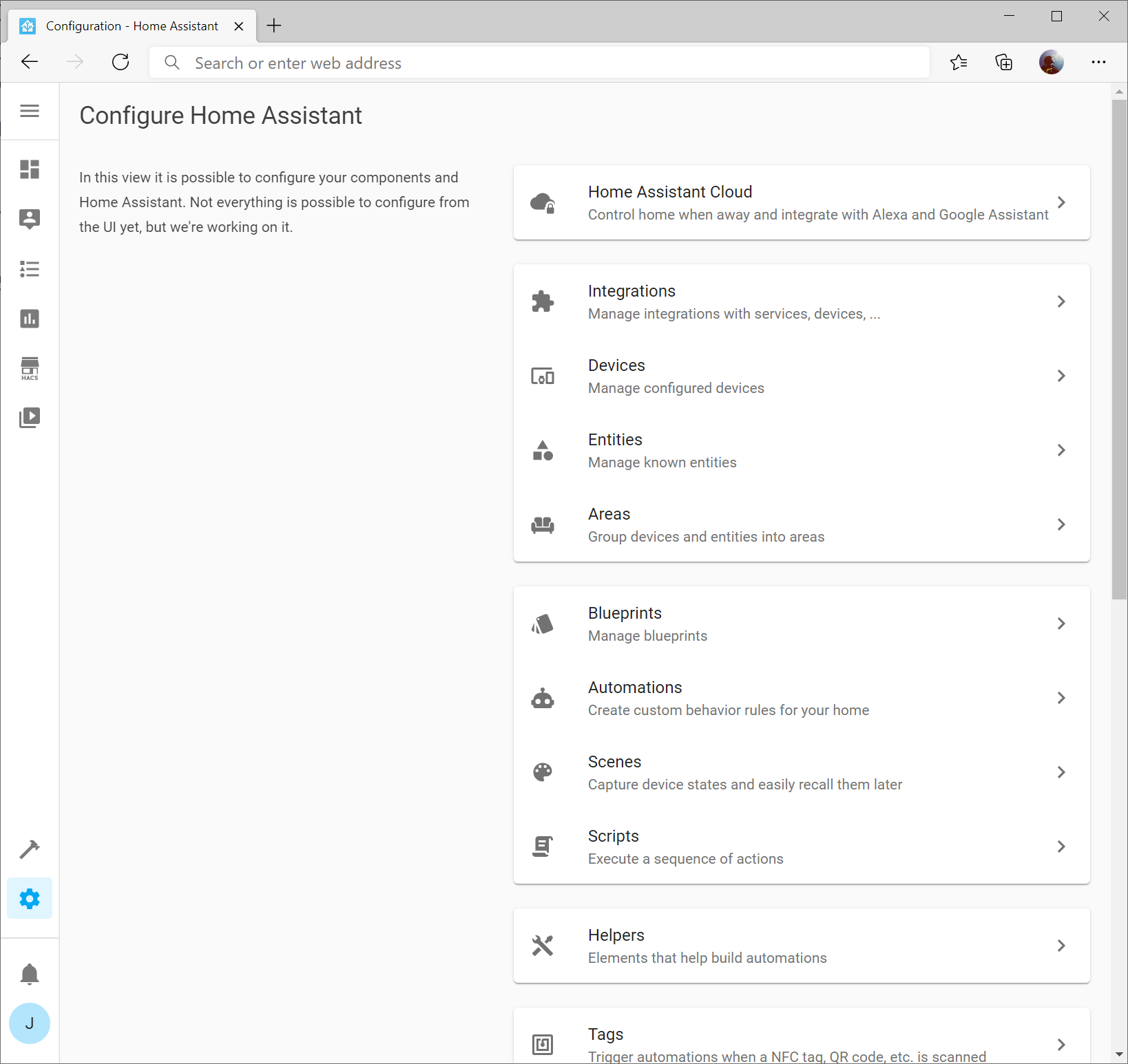
Navigate to Configuration -> Integrations
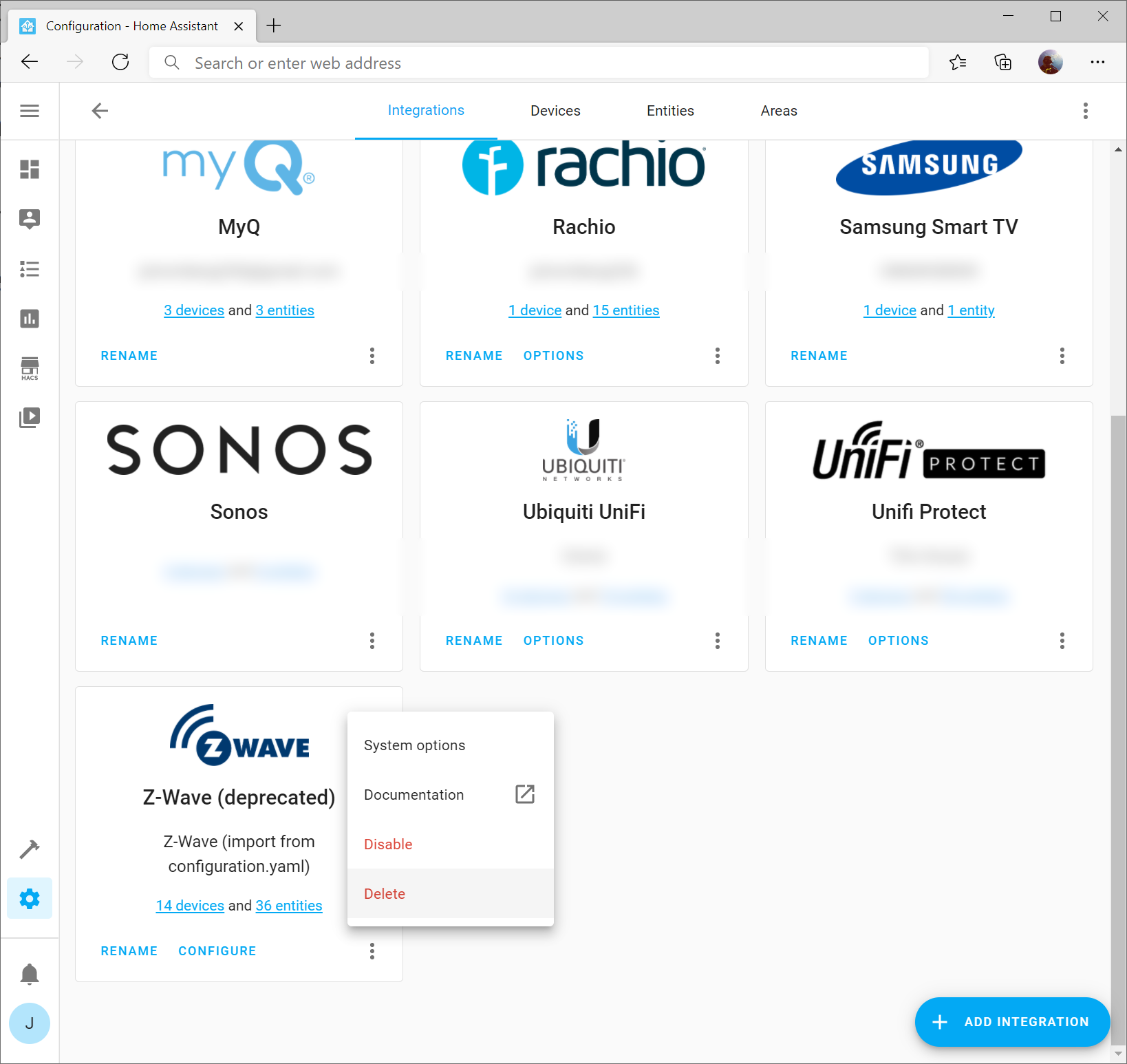
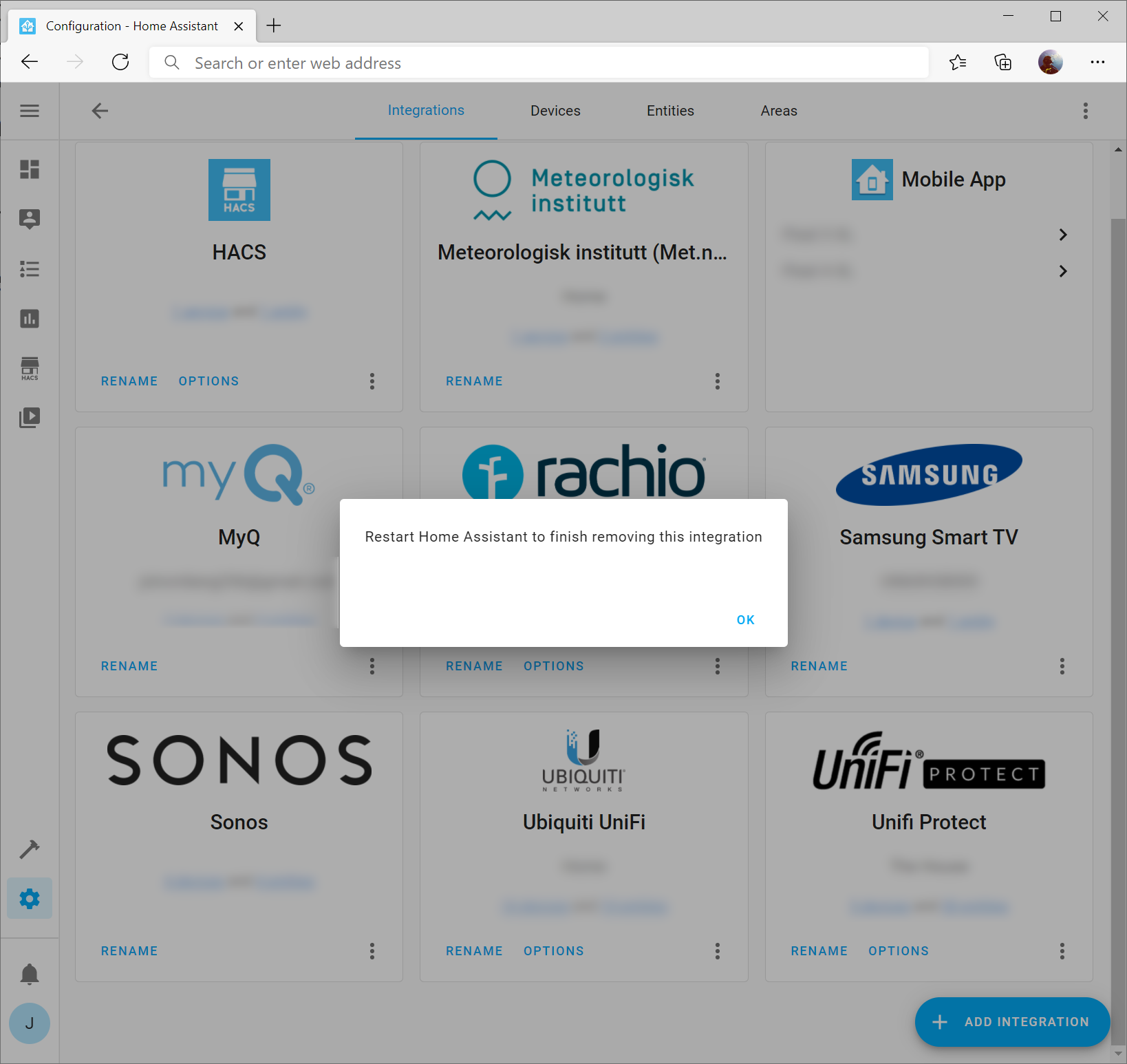
Click the three dots on the Z-Wave integration and select Delete
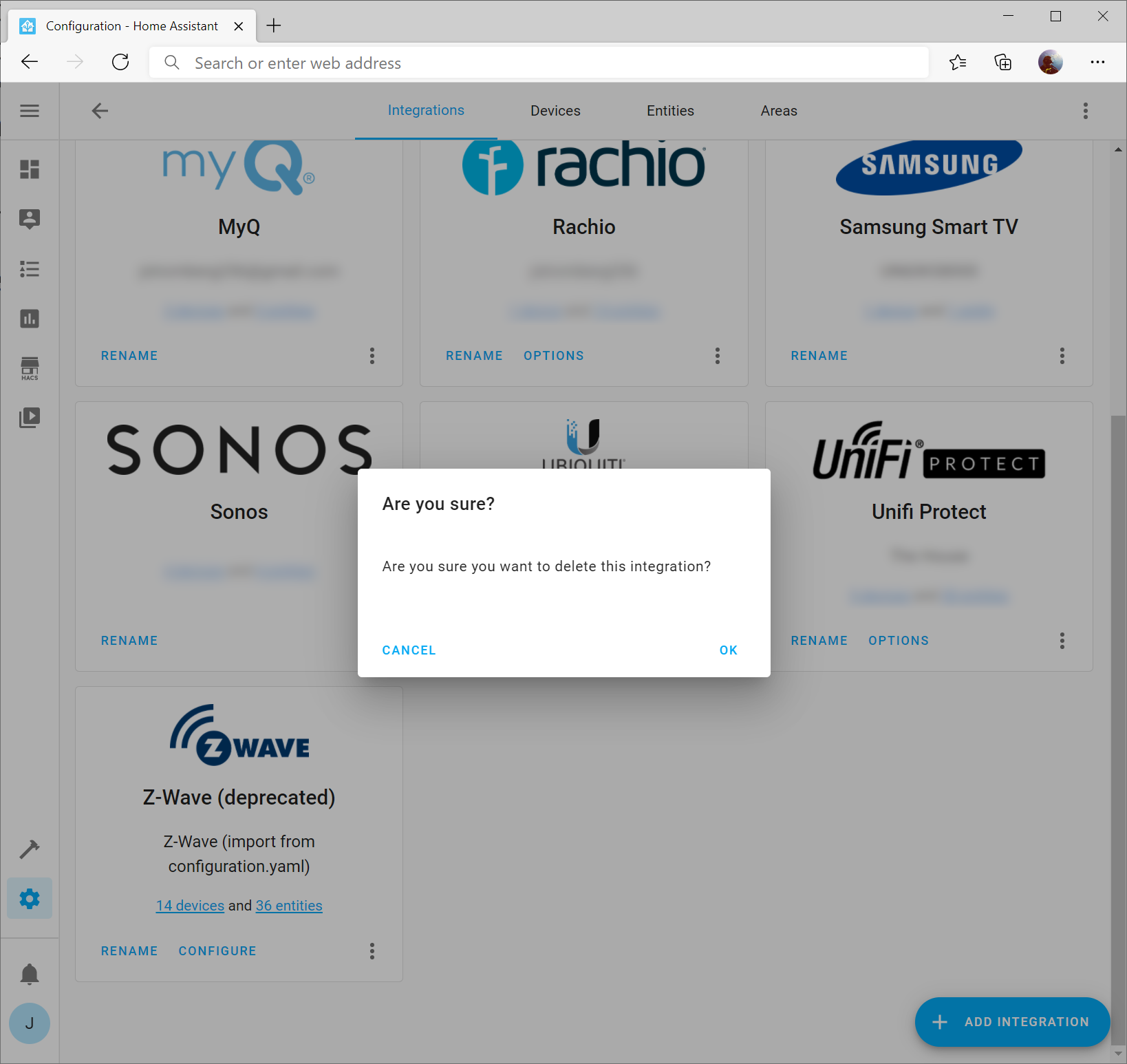
Click OK when prompted
Click OK on the prompt that you should restart home assistant (it won’t restart home assistant at this point)
Restart Home Assistant
While we can restart Home Assistant from the web UI, we need to ensure that the Docker container running home assistant no longer needs access to your Z-Wave stick directly (Z-Wave JS Server will be what interfaces with the device directly). In this case, you will need to SSH into your Home Assistant server and stop / remove / start the container accordingly.
Stop the Docker container
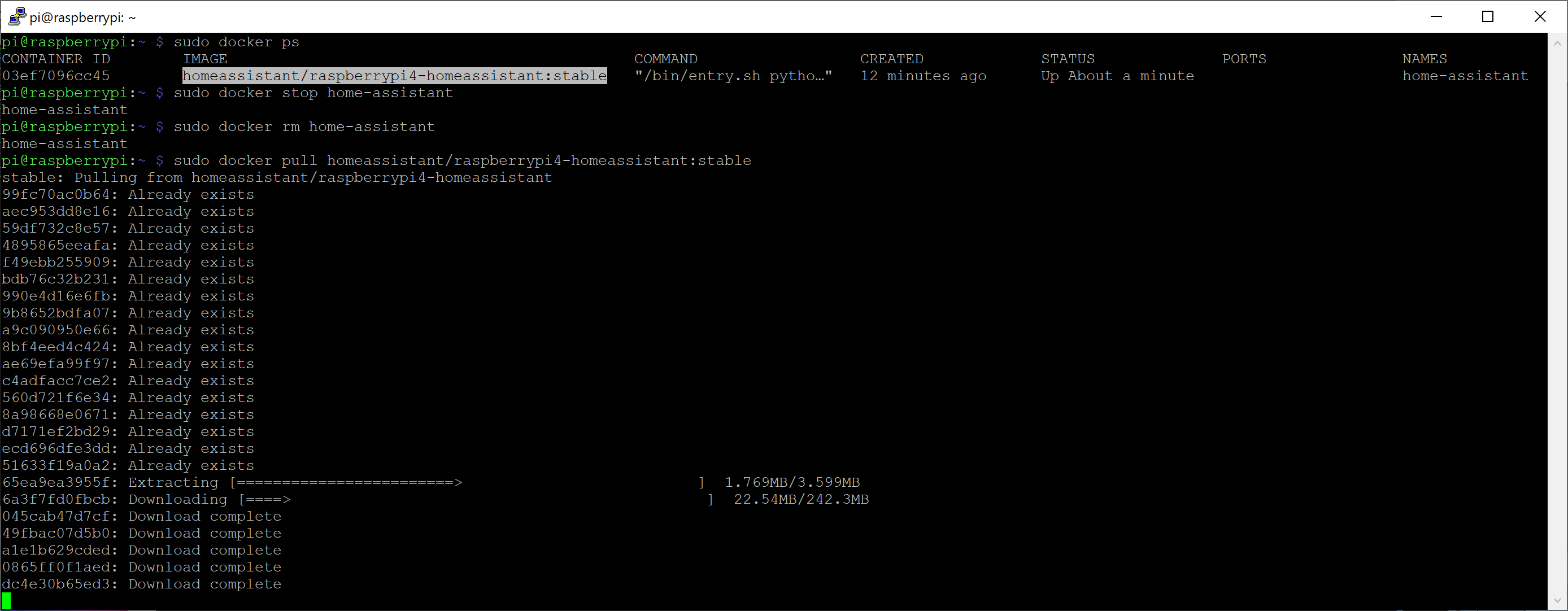
sudo docker stop home-assistant
Remove the container
sudo docker rm home-assistant
Deploy the new container configuration, which removes any device mappings to your Z-Wave stick/device
Disable MQTT Gateway: Can be enabled if you have no use for MQTT
Click the Home Assistant menu and set the following:
WS Server: Enabled
Server Port: 3000
Click SAVE
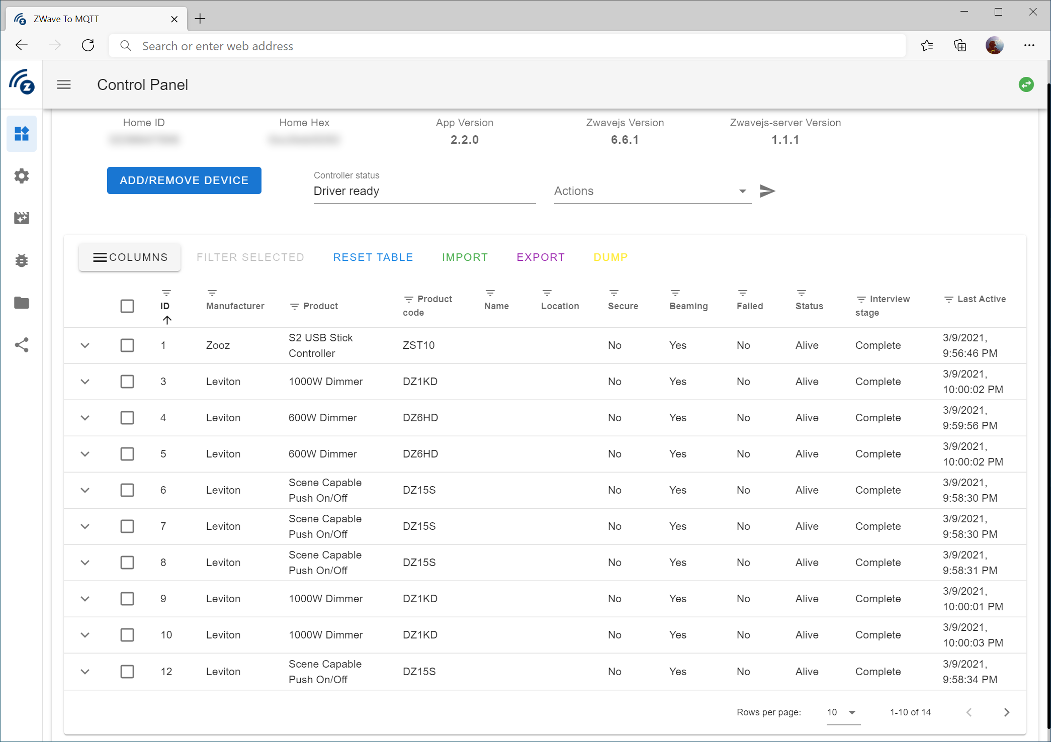
Verify you see devices
Click on the Control Panel icon on the top left of the Z-Wave JS Web UI. Verify that you see the amount of devices you previously had.
At this point, I would recommend waiting a few minutes / possibly hours to let the table populate with all the device information.
Install Z-Wave JS Integration
I would recommend a full refresh of the web page for Home Assistant and then navigate back to Configuration -> Integrations
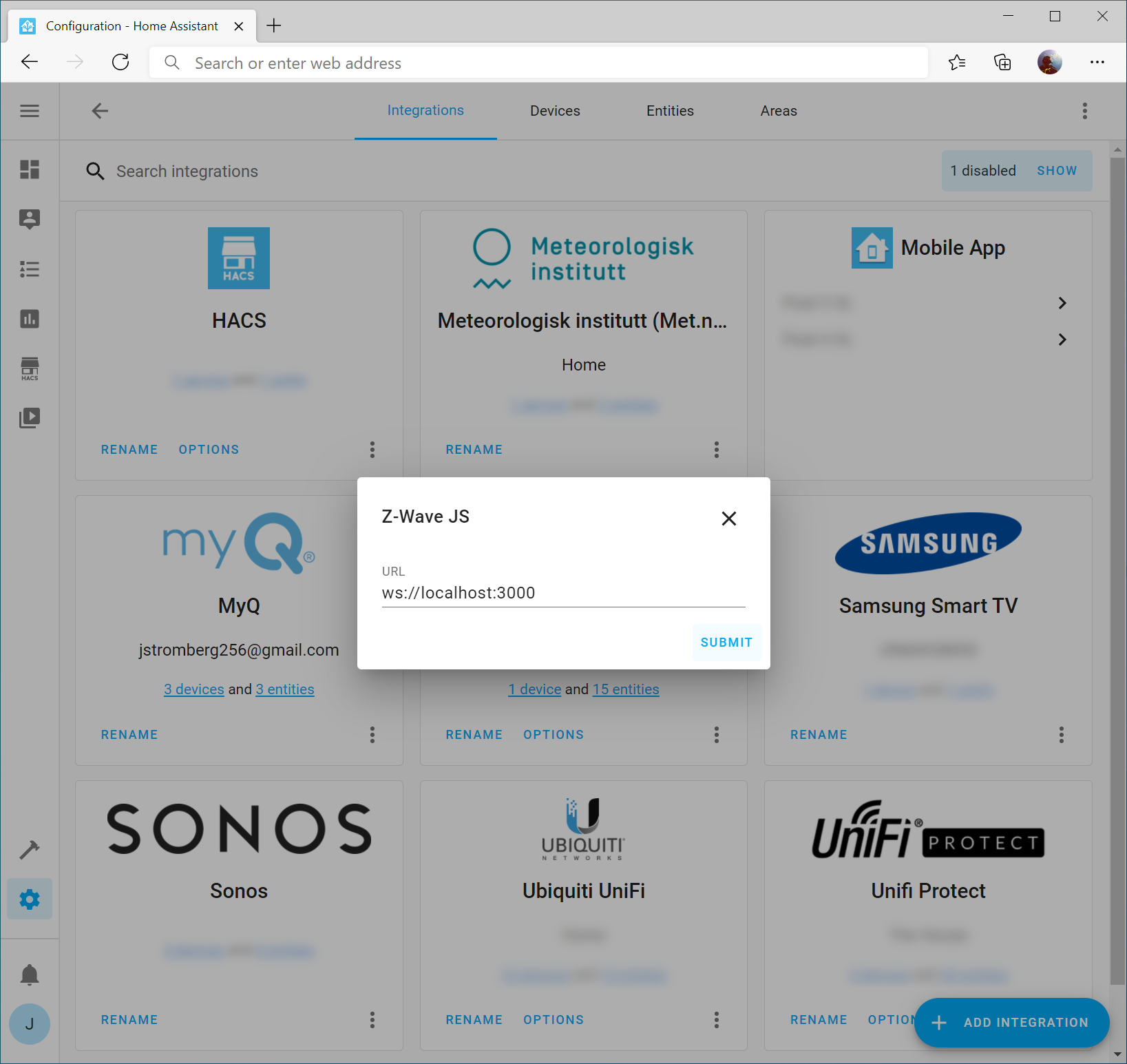
Click the Add Integration button and search for Z-Wave JS
Click Submit to accept the URL as-is (assuming you are running the container on the same server running the Home Assistant container; if not, you can specify the IP address of the server hosting the Z-Wave JS Server container as well).
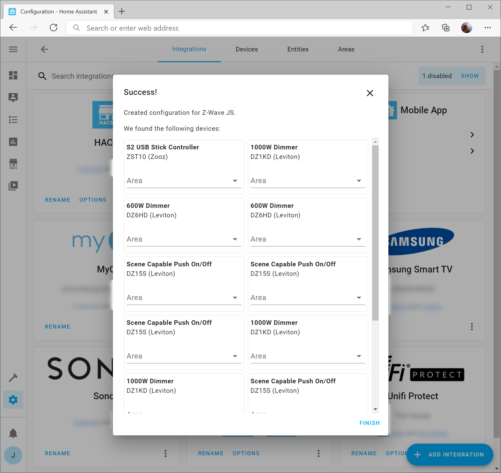
If all went well, you should see your Z-Wave devices and you can click Finish (Note: I wouldn’t worry about specifying Areas since it’s likely you have no idea what device is what at this point)
Update your Z-Wave Device Names in Home Assistant
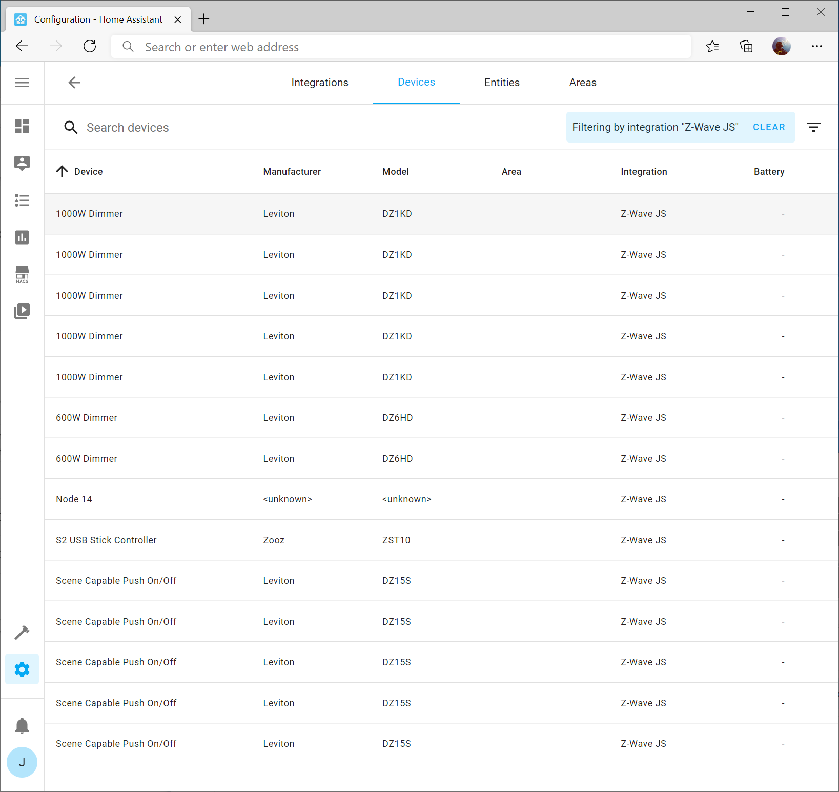
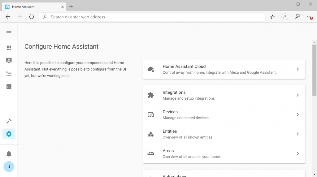
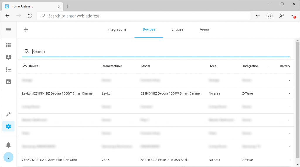
The last step is to update your device names to match your existing device names. To do this, on the Configuration -> Integrations page, select the devices link on the Z-Wave JS integration tile
Next, select one of the items in your list. In my case, I’m going to select the first 1000W Dimmer I have.
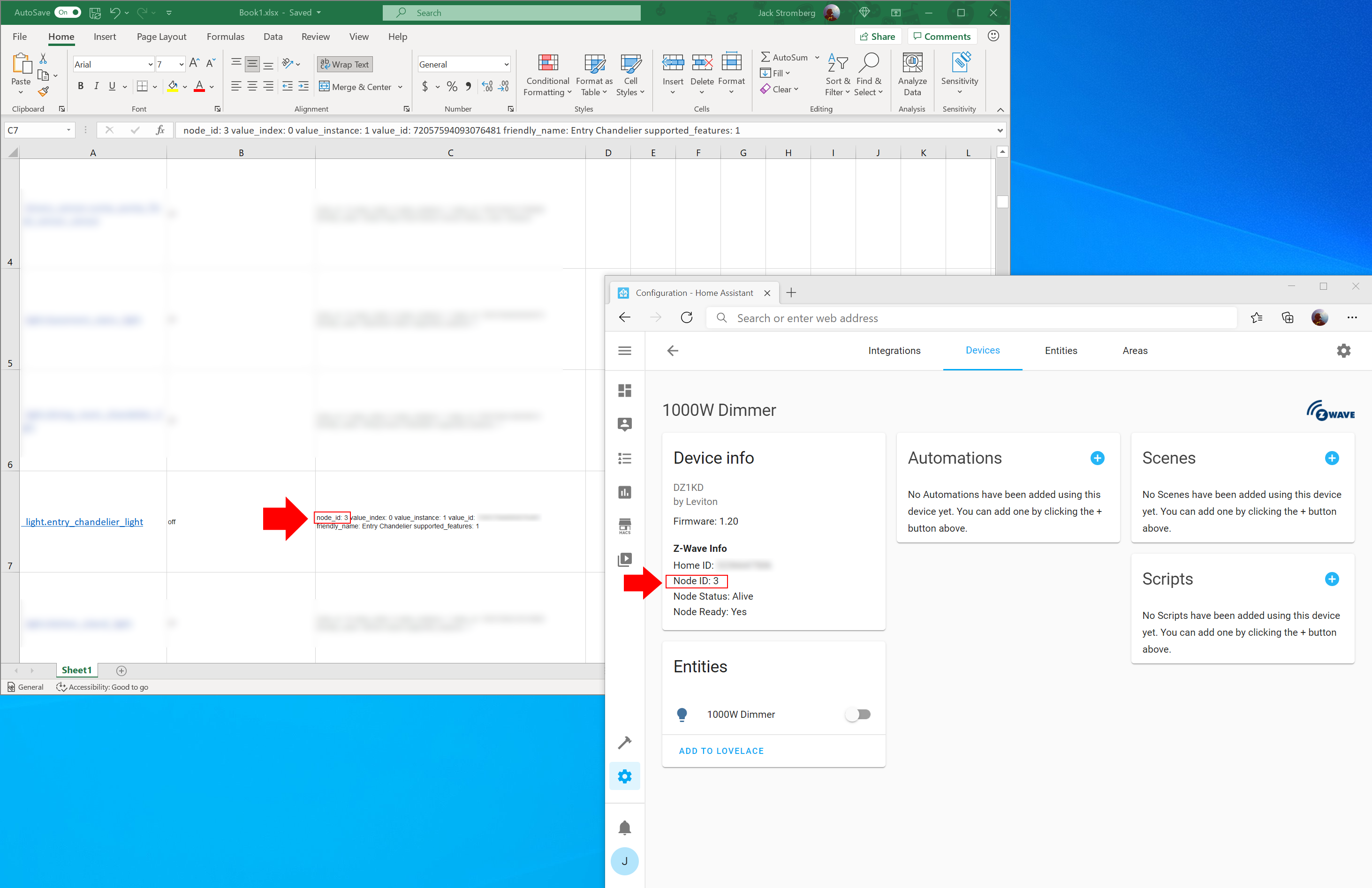
On the device, you should see Node ID. This can be looked up on your list of devices you exported in the previous steps.
Click the Device Name (in my case 1000W Dimmer) and specify the correct information for the device. Once done, click Update
Rinse and repeat
Go through each of the devices you have and update their corresponding names. If you click Advanced settings, you can specify the area for the device as well.
Congrats!
If you’ve made it this far, you have successfully migrated to the latest Z-Wave integration for Home Assistant!
Many Azure services allow you to bring your own SSL Certificate to the cloud. While Azure provides an easy way to create and deploy resources through ARM templates, specification of what SSL certificate is a little less trivial since it’s not as easy to specify an exported PEM or PFX file. In this case, Azure may look for the certificate in a base64 encoded format, so the certificate can be passed as a string (or list of characters) into the template.
Goal of this tutorial
This tutorial will walk through the commands needed to generate a self-signed certificate that is base64 encoded via PowerShell (Option 1) or base64 encode an existing PFX (Option 2), so that the certificate can be passed as a parameter into ARM templates in Azure.
Option 1: Generate and encode a self-signed certificate
At this point, if you open selfSignedCertificate.txt, you should see a long list of characters compromised of letters, numbers, and a few symbols, which is your base64 version of your certificate. See example below (…s denote I removed a large portion of the text, you won’t see that in your file).
This text can be used-as within your templates now (although, in general, try to never code these values into your templates, these values should be passed as parameters into the template).
Here’s a quick cheat sheet on recommended subnet sizing for Azure. Items in bold are subnet names reserved by the platform for their corresponding service.
Continuing from my previous guide on how to setup Home Assistant + Docker + Z-Wave + Raspberry Pi, this tutorial will show you how to update Home Assistant to the latest version. Updating Home Assistant to the latest version is critical to ensure you have the latest bug fixes, integrations, and security patches.
Note: during the update your devices will continue to work fine, but please note any automations or access to the application will not be available, so it’s recommended to do this during a time that you know no automations will be running.
Validate your current version
Navigate to the Developer Tools section of Home Assistant. Here you can validate the latest version you currently have deployed.
Get the current name of your container and version
sudo docker ps
In running this command, note the NAME of your container as well as the IMAGE.
Stop and delete the container
Replace the name of the container in the command below with the value you had.
Make sure your replace the name and value of the image with the values in the previous step. In addition, ensure you specify the correct path to where you existing configuration files exist to have the container load your existing configurations.
Note: If you are now using the Z-Wave JS docker container, you will not want to attach the Z-Wave stick to the Home-Assistant container. In this case, run the following command:
In newer versions of the docker container –init should not be specified in the docker run command. Specifying –init will result with the following error: “s6-overlay-suexec: fatal: can only run as pid 1”. This was mentioned as a breaking change in: 2022-06-01 update: 2022.6: Gaining new insights! – Home Assistant (home-assistant.io)
Notice: Home Assistant has released a new integration called Z-Wave JS. You should be using that integration vs the older Z-Wave integration that this article covers. I will be updating this guide soon.
A few years back I had a SmartThings Hub and for the most part it worked great. It was simple to setup, can be accessed anywhere, and for the most part automatically updated itself. Unfortunately, with the acquisition of it by Samsung, it seems to have turned into bloatware with poor responsiveness, the mobile application’s UI is horrific, and they have a less than desirable security/privacy policy.
Luckily, the open source community has thrown together Home Assistant, an open source home automation project backed by hundreds/thousands of individuals. Over the years, they have now brought native support for mobile devices, at time of writing this there are 1500+ integrations for dang near any device, and the software puts you in control of who has access to and where your data is accessible.
The one trade-off though is while Home Assistant works well and is very extensible, the documentation and usability of the application can be overwhelming to understand for someone new to home automation, unfamiliar with Linux/Open Source technologies, or new to debugging/command line interfaces.
In this case, I’ve tried to document a crash course in getting Home Assistant up and running as quickly as possible for those that want to get started with Z-Wave devices and Home Assistant.
Home Assistant will run on any version of Raspberry Pi, but it is recommended to use version 3 or 4 for best performance. In this guide, I use a Raspberry Pi 4 for reference. Below is a link to the Raspberry Pi kit, which contains everything you need to get started.
First things first, update your Raspberry Pi with the latest updates. Open up Terminal or SSH to your Raspberry Pi and execute the following command:
sudo apt-get update && sudo apt-get upgrade
Prepare your Z-Wave USB Stick
Plug in your Z-Wave USB stick. Once plugged in, we need to find the device path so that we can reference it for Home Assistant. Execute the lsusb command to find your device ID. In this case, you can see my device ID begins with 0658.
root@raspberrypi:/dev# lsusb
Bus 002 Device 001: ID 1d6b:0003 Linux Foundation 3.0 root hub
Bus 001 Device 003: ID 0658:0200 Sigma Designs, Inc. Aeotec Z-Stick Gen5 (ZW090) - UZB
Bus 001 Device 002: ID 2109:3431 VIA Labs, Inc. Hub
Bus 001 Device 001: ID 1d6b:0002 Linux Foundation 2.0 root hub
Next, let’s find what the device path is for the USB stick. You can do this by executing the following command: dmesg | egrep ‘0658|acm’ Please note, if you purchased a difference device, 0658 may be a different number. In this case, you can see my device is presented on ttyACM0.
root@raspberrypi:/dev# dmesg | egrep '0658|acm'
[    1.405327] usb 1-1.2: New USB device found, idVendor=0658, idProduct=0200, bcdDevice= 0.00
[    3.468875] cdc_acm 1-1.2:1.0: ttyACM0: USB ACM device
[    3.471348] usbcore: registered new interface driver cdc_acm
[    3.471359] cdc_acm: USB Abstract Control Model driver for USB modems and ISDN adapters
Install Docker
Home Assistant doesn’t require Docker, but by leveraging Docker you can easily copy/backup your configuration and simply redeploy the container if something goes wrong. As updates are made, you can simply remove your container and redeploy. To install Docker, execute the following command:
curl -sSL https://get.docker.com | sh
Deploy Home Assistant Docker Container
Once Docker is installed, you can deploy the container from Docker Hub. Docker Hub is a public repository that has tons of different prebuilt containers to deploy. Here you can find the official homeassistant containers: https://hub.docker.com/u/homeassistant
To deploy the container, execute the following line, replacing the following variables with your desired configuration:
This allows the container to leverage the Z-Wave USB device. Make sure you specify the path to your device found in the previous step
-v /home/docker/home-assistant:/config
This is the path that the home assistant configuration files should be stored to. You can specify a fileshare or other path to place your configuration files.
The first half of this is the container you wish to deploy and the second half is the version. You can find all of Home Assistant’s official containers here: https://hub.docker.com/u/homeassistant
Note: In newer versions of the docker container –init should not be specified in the docker run command. Specifying –init will result with the following error: “s6-overlay-suexec: fatal: can only run as pid 1”. This was mentioned as a breaking change in: 2022-06-01 update: 2022.6: Gaining new insights! – Home Assistant (home-assistant.io)
Setup Home Assistant
Give the container a few minutes to deploy and configure itself for the first time. After a few minutes, try opening your web browser and navigating to the IP address assigned to your machine, using port number 8123: http://192.168.1.2:8123/
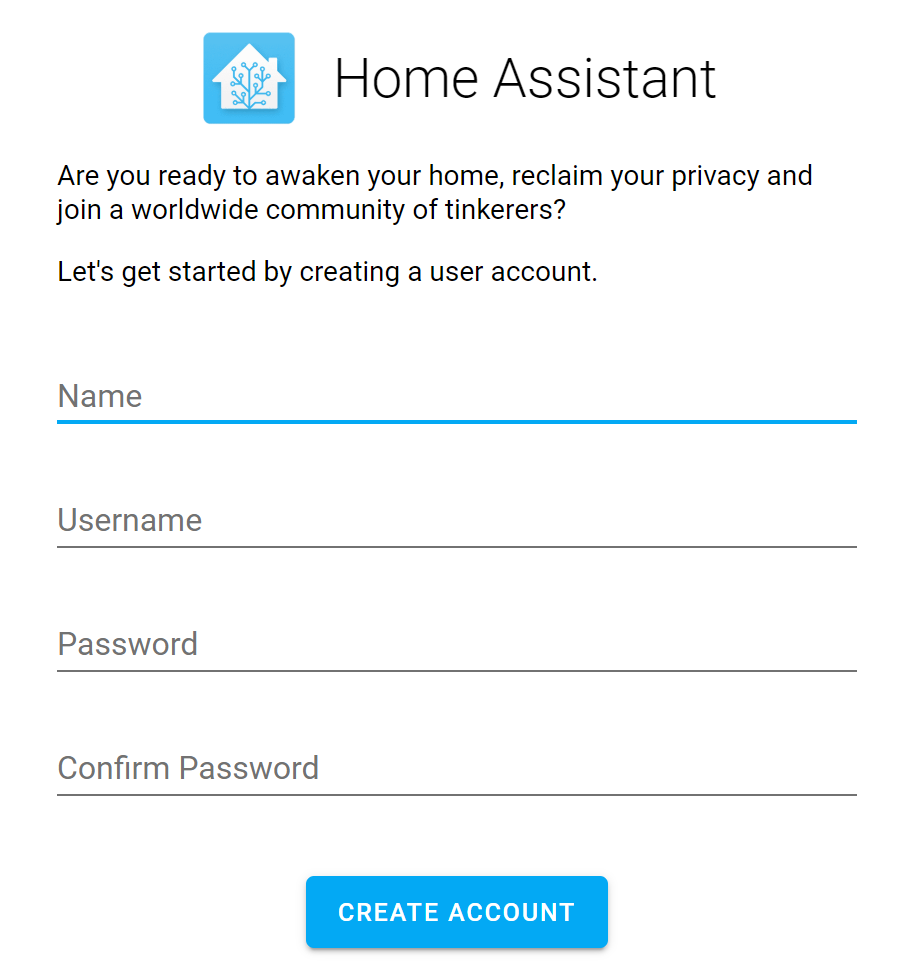
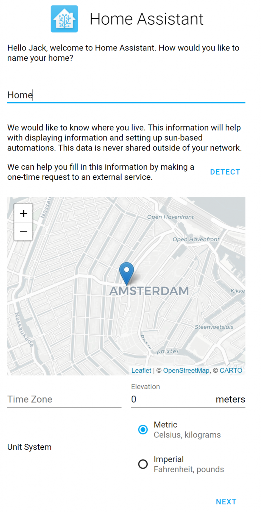
When the page loads, it should first ask for your Name, Username, and Password. This is the username and password you will use to login to Home Assistant.
Next, specify the location of where your Home Assistant deployment is located. Oddly enough, you cannot type in a location, but you can place the pin near your location by dragging the map around and clicking once to set the pin.
Once you click Next, Home Assistant may have already found a few devices connected to your network. You can add them now or skip and add them later.
Tell Home Assistant to use your Z-Wave USB Stick
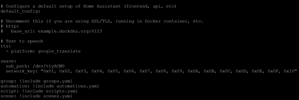
Although we granted access to the container to use the Z-Wave USB Stick, you need to tell Home Assistant how to leverage the device. To do so, you will need to open up Terminal or SSH to your machine and edit the configuration.yaml file to point to the device. Before we get into modifying the configuration.yaml file, first execute the following command to generate a Z-Wave Security Key. This key may be required by Z-Wave security devices (Door Locks, Keypads, etc), as an extra layer of security. More information on this can be found here: https://www.home-assistant.io/docs/z-wave/adding#network-key
Execute the following command via Terminal or SSH:
Next, we need to edit the configuration.yaml file, which can be found in the path specified when the Docker container was deployed (using the -v parameter). For the purpose of this article, /home/docker/home-assistant/configuration.yaml is where the file is located. Using your favorite text editor, add the following lines of code:
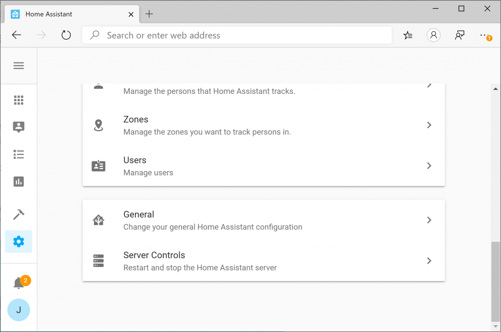
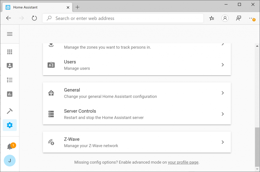
Once saved, go back to Home Assistant and click the Gear icon and then select Server Controls
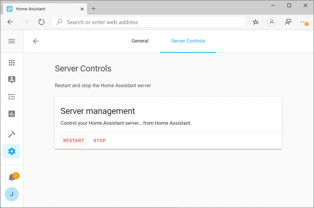
Select the Restart button to restart Home Assistant. Any time you make a change to the configuration.yaml file, you will need to restart Home Assistant to pickup the configuration changes.
Click OK to Restart
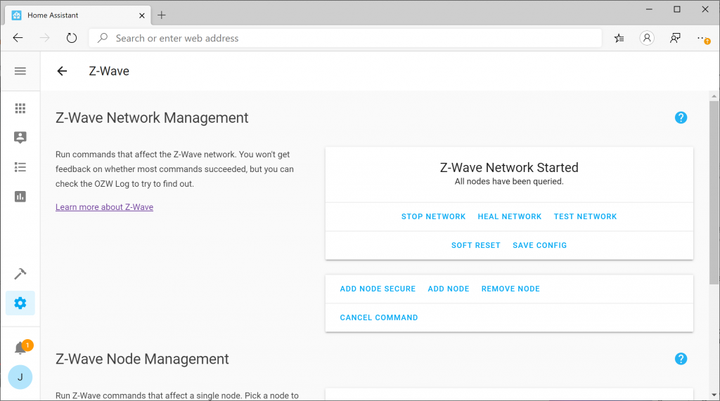
Upon restart, navigate back to the Gear icon and you should see a new entry in the Config portal for Z-Wave. If you do not see the “Z-Wave” section, scroll down to the troubleshooting step at the end of this article.
Add a Z-Wave device
Once you see that your Z-Wave network has started, adding a device is a piece of cake. First click the Add Node button. When you click the button, nothing will happen, but go ahead and put your device in inclusion mode. Once the device is in inclusion mode, Home Assistant should automatically add the device.
At this point, if you navigate back to Configuration (Gear icon) and select Devices
You should see your newly added Z-Wave device!
At this point, you can select the Device to give it a friendly name or start to work on building your own home automation actions.
Hope this helped! If you have any comments or suggestions on how to improve this guide, please drop it below.
Troubleshooting Missing Z-Wave Configuration
The first time I ran through this, I noticed I was missing the Z-Wave configuration tile after making changes to the configuration.yaml file. It turned out I specified the wrong device path in the configuration file. To verify, you can check the logs from your Docker container by executing the following command in your Terminal or via SSH. (Replace home-assistant with the name of your container if you specified something else)
sudo docker logs home-assistant
In my case, I had the following error:
2020-02-16 21:08:01 INFO (MainThread) [homeassistant.components.scene] Setting up scene.homeassistant
2020-02-16 21:08:02 INFO (MainThread) [homeassistant.components.zwave] Z-Wave USB path is /dev/ttyACM01
2020-02-16 21:08:02 ERROR (MainThread) [homeassistant.config_entries] Error setting up entry Z-Wave (import from configuration.yaml) for zwave
Traceback (most recent call last):
  File "/usr/local/lib/python3.7/site-packages/openzwave/option.py", line 78, in __init__
    raise ZWaveException(u"Can't find device %s : %s" % (device, traceback.format_exception(*sys.exc_info())))
openzwave.object.ZWaveException: "Zwave Generic Exception : Can't find device /dev/ttyACM01 : ['NoneType: None\\n']"

During handling of the above exception, another exception occurred:

Traceback (most recent call last):
  File "/usr/src/homeassistant/homeassistant/config_entries.py", line 215, in async_setup
    hass, self
  File "/usr/src/homeassistant/homeassistant/components/zwave/__init__.py", line 369, in async_setup_entry
    config_path=config.get(CONF_CONFIG_PATH),
  File "/usr/local/lib/python3.7/site-packages/openzwave/option.py", line 81, in __init__
    raise ZWaveException(u"Error when retrieving device %s : %s" % (device, traceback.format_exception(*sys.exc_info())))
openzwave.object.ZWaveException: 'Zwave Generic Exception : Error when retrieving device /dev/ttyACM01 : [\'Traceback (most recent call last):\\n\', \'  File "/usr/local/lib/python3.7/site-packages/openzwave/option.py", line 78, in __init__\\n    raise ZWaveException(u"Can\\\'t find device %s : %s" % (device, traceback.format_exception(*sys.exc_info())))\\n\', \'openzwave.object.ZWaveException: "Zwave Generic Exception : Can\\\'t find device /dev/ttyACM01 : [\\\'NoneType: None\\\\\\\\n\\\']"\\n\']'
Here you can see I accidentally specified /dev/ttyACM01 vs /dev/ttyACM0. Simply updating the configuration.yaml file with the correct device path solved the issue.
This tutorial will review how to create a bootable USB drive to flash the fimrware/bios on your Lenovo device.
Before we begin, Lenovo offers three different downloads for Firmware today:
Windows installer/flash utility (.exe)
CD ISO version (.iso) to burn to a disk
USB Flash Package (.zip)
While the USB Flash Package (.zip) is exactly what we are looking for, by default if you just drag the files onto your USB drive, it won’t boot to the flash utility. In this case, the instructions below will show you have to make the drive bootable and then launch the USB Flash Package.
Make a bootable drive
First, you will want to download a copy of the Rufus utility. This utility is an open source utility for Windows only, but will allow you to make a bootable USB drive. You can obtain a copy of the utility here. Rufus’ website can officially be found here: https://rufus.ie/
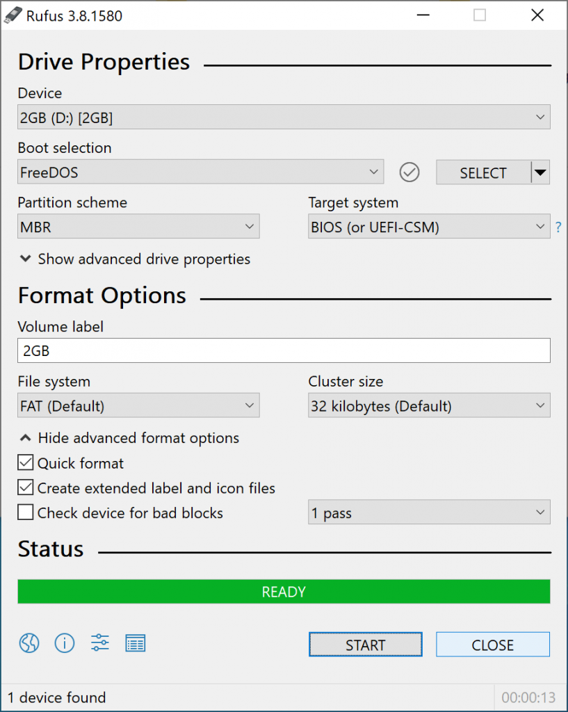
Once installed, open the application. Select your USB device you wish to flash (note this will erase all data on your device) and set the Boot selection to FreeDOS. Once your Device and Boot selection has been set, go ahead and click Start to flash the device.
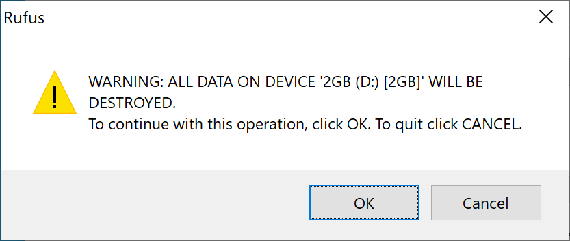
You will be prompted to confirm you are OK with erasing the device. Go ahead and click OK if you are sure you have selected the correct device in the prior step.
Once completed, you should see a green bar that says READY. This is kinda misleading, wish it would say completed, but your device should be flashed at this point.
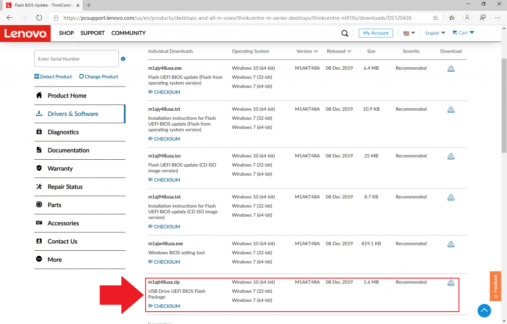
Download the right firmware from Lenovo
As mentioned earlier, Lenovo offers 3 different types of downloads on their website. You will want a copy of the zipped installer as shown in the screenshot below.
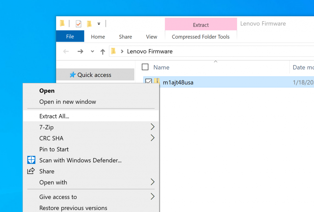
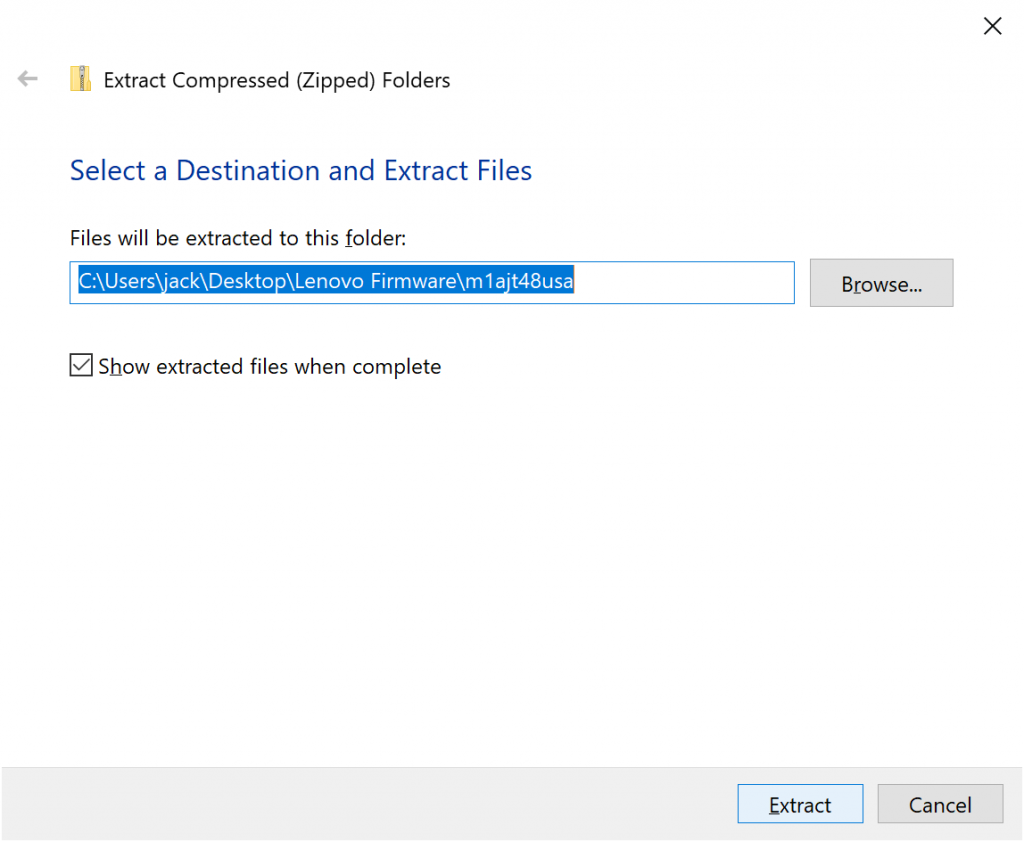
Once downloaded, navigate to where you downloaded the zipped file, right click, and select Extract All… If you don’t see Extract All… then try downloading a copy of 7-Zip, which is a fantastic free archiver solution that can open all types of compressed files (zip, 7zip, tar.gz, etc)
In this picture, we show right clicking the zipped folder and clicking Extract All… on the file.In this picture, we are selecting the folder to where the extracted files should go.
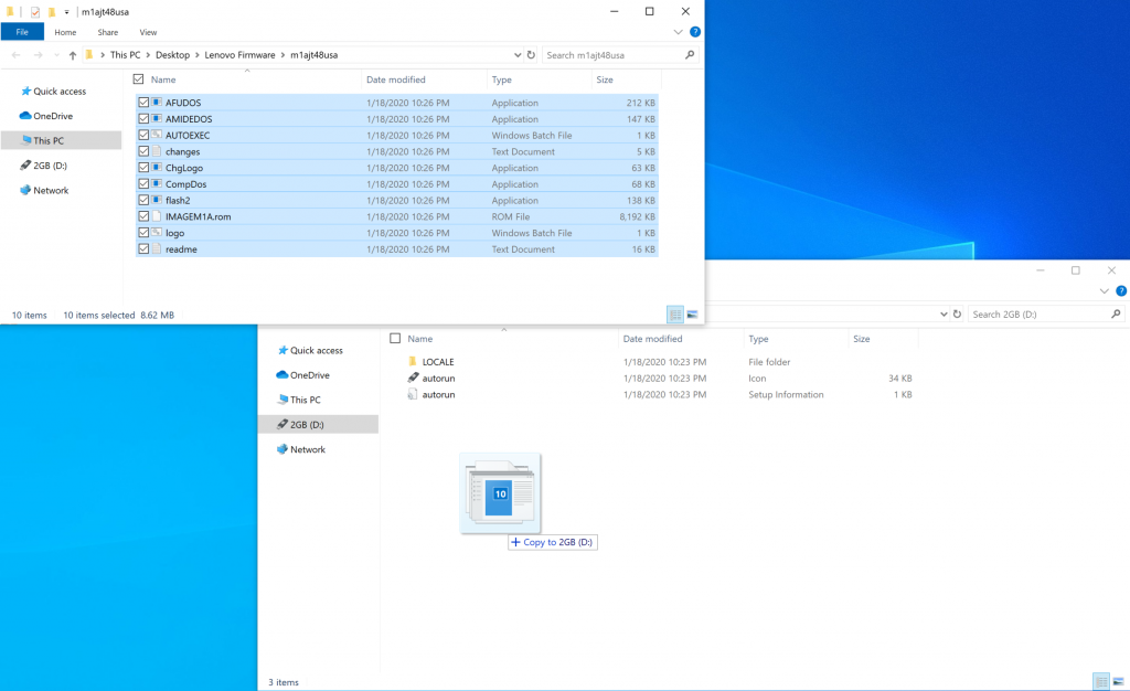
Copy the extracted files to your bootable USB drive
Once you have extracted the files from the zipped folder from Lenovo, you will want to copy and paste the files from the extracted directory to the bootable USB drive. To show visually, I opened two file explorer windows, one in the directory of the extracted firmware and the other on the bootable USB drive. I simply dragged and dropped the files from the firmware directory to the bootable USB drive.
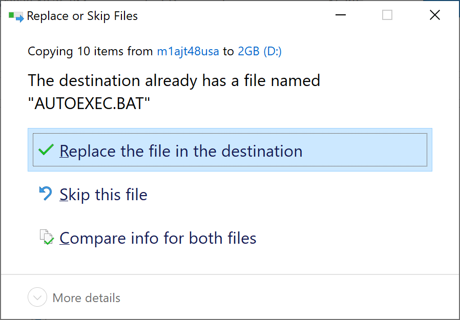
When you try to copy the files from the firmware directory to the bootable USB drive, you will be prompted to replace AUTOEXEC.BAT. Make sure to Replace the file in the destination as this will execute the command to launch the flash2 utility, which actually writes the firmware to the device.
Plug in the drive and set the device to boot to it
At this point, you should have a bootable USB device that you can now plugin to your Lenovo device. You can unplug it from your client machine and plug it in to your Lenovo device. Make sure you set your Lenovo device to boot from the USB drive (this can usually be set by pressing the F1 or F2 keys during the post screen).
What to expect
Upon boot, you should be greeted by the Lenovo flash utility, which will ask if you want to update your device. Please note, that in my experience, once I select yes the device needed to reboot several times and may boot into the BIOS. The utility will tell you when everything is completed, so make sure you don’t power down your device or unplug your USB drive after the first or second reboot, make sure you wait things out. As with updating any firmware, make sure you don’t do this in a storm or on a device with low battery as you ensuring little chance of disruption as possible is absolutely critical.
Summary
At this point, you should have a bootable USB drive created by Rufus and FreeDOS that can be paired with Lenovo’s firmware to go around and flash your devices. Hope this helps!