Headless Raspberry Pi Image based on Debian Trixie (Like Raspbian Lite)

I'm in the process on repurposing a few Raspberry Pis and noticed Debian 13 has officially been released (at time of writing), but Raspberry Pi OS is still on Debian 12.

If you're looking to create a custom Raspberry Pi OS image tailored for headless deployment, this guide walks you through using the official pi-gen tool to build your own image โ€” based on Debian Trixie (Debian 13).

While I've tried to write this document in the context of a how-to, it's more of a reflection on what I did vs something formal.

โš ๏ธ Disclaimer: Since this image is not built or maintained by the Raspberry Pi Foundation, you may encounter compatibility issues, hardware quirks, or missing Raspberry Pi-specific features. Official support for this setup is limited, and it's best suited for experimentation or advanced use cases. I don't work for the Raspberry Pi project, so follow at your own risk.

That all being said, here's what following this page would yield:

  • Uses the same tool the Raspberry Pi Foundation uses to generate official images
  • Builds a minimal system similar to Raspberry Pi OS Lite
  • Builds an Arm64 image (not 32-bit)
  • Has SSH enabled
  • Supports customization of locale, timezone, and user credentials

โœ… Why Build Your Own Image?

You may want a custom image when:

  • You need headless deployment out of the box (no keyboard/mouse/monitor)
  • You want SSH access enabled by default
  • You want to preconfigure locales or packages for embedded or production use

๐Ÿ”ง Prerequisites

To follow this guide, it assumes usage of a few linux utilities / command. It assumes you are using and have available:

  • A macOS (Apple Silicon) or Linux machine
  • git, docker, and optionally qemu-user-static (only needed for x86)
  • ~10โ€“20GB of free disk space

๐Ÿงฐ Step 1: Clone pi-gen

git clone --branch arm64 https://github.com/RPi-Distro/pi-gen.git
cd pi-gen

From the docs at time of this article:

Note: 32 bit images should be built from the master branch. 64 bit images should be built from the arm64 branch.

Tip: They have different branches based on debian OS version you want to target.


๐Ÿงพ Step 2: Create the config File

You can define a file to customize that tells the image how to be customized out of box. Since we are a headless setup, we don't want to have to connect a monitor, keyboard, mouse, etc; so this file will define how the operating system should be customized on first startup.

Inside the pi-gen directory, create a file named config:

touch config

Then edit it with your preferred editor (nano, vim, VSCode, etc.):

Example config File

# Debian release to build (note, you should target the applicable branch when changing releases)
RELEASE=trixie

# Name of the image
IMG_NAME="raspios-trixie-arm64"

# Build 64-bit image
ARCH=arm64

# Enable SSH by default
ENABLE_SSH=1

# Set default username and password
FIRST_USER_NAME="pi"
FIRST_USER_PASS="raspberry"

# Don't compress the image โ€“ output raw .img file
DEPLOY_COMPRESSION=none

# Set timezone to UTC+0
TIMEZONE_DEFAULT="Etc/UTC"

# Don't use QEMU (set to 1 if not on Arm based architecture)
USE_QEMU=0


๐ŸŒ Locales, Keyboard, and Timezone

To change the system locale or timezone, you can add these optional variables:

# Locale
LOCALE_DEFAULT="en_US.UTF-8"

# Keyboard layout
KEYBOARD_KEYMAP="us"
KEYBOARD_LAYOUT="English (US)"

# Timezone (examples)
TIMEZONE_DEFAULT="Etc/UTC"       # UTC+0
TIMEZONE_DEFAULT="America/New_York"
TIMEZONE_DEFAULT="Europe/London"
TIMEZONE_DEFAULT="Asia/Tokyo"

You can find all available timezones on a Linux system via:

ls /usr/share/zoneinfo

๐Ÿ—๏ธ Step 3: Build the Image

If you don't want the desktop environment (headless setup), create the following skip files to eliminate creation of the full desktop images:

touch ./stage3/SKIP ./stage4/SKIP ./stage5/SKIP
touch ./stage4/SKIP_IMAGES ./stage5/SKIP_IMAGES

To start the build, run the following:

./build-docker.sh

This will:

  • Pull the necessary Docker images
  • Run through the build stages (stage0 to stage2 (assuming you created the skips))
  • Output a raw .img file(s) in the deploy/ folder

Example output without skip

copying log from container pigen_work to deploy/
total 35235816
drwxr-xr-x  10 jack  staff   320B Sep  6 11:58 .
drwxr-xr-x  23 jack  staff   736B Sep  6 11:57 ..
-rw-r--r--   1 jack  staff   8.3G Sep  6 11:57 2025-09-06-raspios-trixie-arm64-full.img
-rw-r--r--   1 jack  staff   245K Sep  6 11:57 2025-09-06-raspios-trixie-arm64-full.info
-rw-r--r--   1 jack  staff   2.6G Sep  6 11:56 2025-09-06-raspios-trixie-arm64-lite.img
-rw-r--r--   1 jack  staff    76K Sep  6 11:56 2025-09-06-raspios-trixie-arm64-lite.info
-rw-r--r--   1 jack  staff   5.8G Sep  6 11:56 2025-09-06-raspios-trixie-arm64.img
-rw-r--r--   1 jack  staff   213K Sep  6 11:56 2025-09-06-raspios-trixie-arm64.info
-rw-r--r--   1 jack  staff   1.0M Sep  6 11:58 build-docker.log
-rw-r--r--   1 jack  staff    10K Sep  6 11:57 build.log

Example output with the skip files

copying results from deploy/
copying log from container pigen_work to deploy/
total 5525296
drwxr-xr-x   6 jack  staff   192B Sep  6 12:03 .
drwxr-xr-x  23 jack  staff   736B Sep  6 12:03 ..
-rw-r--r--   1 jack  staff   2.6G Sep  6 12:03 2025-09-06-raspios-trixie-arm64-lite.img
-rw-r--r--   1 jack  staff    76K Sep  6 12:03 2025-09-06-raspios-trixie-arm64-lite.info
-rw-r--r--   1 jack  staff   308K Sep  6 12:03 build-docker.log
-rw-r--r--   1 jack  staff   5.8K Sep  6 12:03 build.log

๐Ÿ’พ Step 4: Flash the Image to SD Card

After the build completes, write the image to an SD card. You can do this via command line or via the official Raspberry Pi Imager.

WARNING: make absolutely sure if you use the commands below you do not target the wrong disk. These commands can result in data loss. You do not hold me liable for data loss if using this approach!

On macOS or Linux:

  1. Identify the SD card:
diskutil list       # macOS
lsblk               # Linux
  1. Unmount the disk (macOS):
diskutil unmountDisk /dev/disk2
  1. Write the image:
sudo dd if=deploy/2025-09-06-raspios-trixie-arm64-lite.img of=/dev/rdisk5 bs=4m conv=fsync

โš ๏ธ Replace /dev/rdisk5 with the correct device for your SD card.


๐Ÿ”Œ Step 5: Boot the Pi

  • Insert the SD card into your Pi
  • Connect an Ethernet cable
  • Power on the Pi

You should:

  • See the Pi boot
  • Get a login prompt (no GUI)
  • Be able to SSH in using the IP address assigned via DHCP

๐Ÿงฉ Optional: Add SSH Key or Preseed Files

You can also preconfigure:

  • Your SSH public key
  • A custom hostname
  • Static IP
  • Additional packages

Let me know if you want a follow-up post for those.


โœ… Recap

FeatureConfigured?
Debian Versionโœ… Trixie (Debian 13)
SSH Enabledโœ… Yes
GUI/DesktopโŒ No
Output Formatโœ… Raw .img
Build Hostโœ… Apple Silicon (no QEMU)
Locale / Timezoneโœ… UTC (editable)

๐Ÿงญ Conclusion

By using pi-gen, you're following the official image-building process used by the Raspberry Pi Foundation โ€” but with full control over your system. This process can also be used for embedded projects, production environments, or anyone who needs a tightly configured headless system.

Configuring an MQTT broker for Home Assistant

I recently purchased a ratgdo device to replace MyQ's kit for a local non-cloud dependent solution. ratgdo offers homekit, mqtt, and Control4, Nice/Elan, or Crestron integration. For this tutorial, I'm going to cover ratgdo and MQTT integration.

If you run Home Assistant as-is or are using their hardware, you can easily setup an MQTT broker by navigating to Add-Ons and installing the MQTT Broker, however in the past I have written articles on Home Assistant and Z-Wave JS as separate containers, so I wanted to follow the same concept by running the MQTT broker as a container as well.

Across the board, the consensus seems to be that most people are running Mosquitto as an MQTT broker, so here is how you can get that setup as a container.

  1. Download the docker image for Mosquitto
docker pull eclipse-mosquitto

2. Create directories for Mosquitto's config and data files. If desired, you can create one for logs as well, but I'm ok not persisting that.

mkdir /home/docker/mosquitto/
mkdir /home/docker/mosquitto/config
mkdir /home/docker/mosquitto/data

3. Create a configuration file for mosquitto. This file will configure what ports MQTT data should be listed on as well as its corresponding port for receiving data via WebSocket. In addition, we will define where data should be stored, and require authentication to be able to connect. For now, leave the password file, which contains the username/password combo for who can authenticate.

vi /home/docker/mosquitto/config/mosquitto.conf

Press i to enter insert mode and paste the following:

listener 1883 0.0.0.0
listener 9001 0.0.0.0
protocol websockets
persistence true
persistence_file mosquitto.db
persistence_location /mosquitto/data/
allow_anonymous false
#password_file /mosquitto/config/passwd

Type !wq to save and quit.

4. Start the mosquitto container. We'll map both the mqtt and websocket ports and volumes for config and data to persist.

docker run -d --restart=always --name="mosquitto-mqtt" -p 1883:1883 -p 9001:9001 -v /home/docker/mosquitto/config:/mosquitto/config -v /home/docker/mosquitto/data:/mosquitto/data eclipse-mosquitto

5. Launch shell on the container

docker exec -it -u 1883 mosquitto-mqtt sh

6. Use the mosquitto_passwd utility to generate an encrypted username and password. An ask for the password will prompt once you run the command. Type exit to return back to your local terminal.

mosquitto_passwd -c /mosquitto/config/passwd mqtt-user
exit

7. Modify your mosquitto.conf file.

vi /home/docker/mosquitto/config/mosquitto.conf

Uncomment the password file by removing the # sign and then type !wq to save and quit.

8. Restart the container so mosquitto will pickup the username/password

docker restart mosquitto-mqtt

At this point, your mqtt broker service should be up and ready! If you'd like to test connectivity and authentication, download a copy of MQTT MQTT Explorer | An all-round MQTT client that provides a structured topic overview (mqtt-explorer.com)

Set out of office / autoreply for distribution list for Exchange online

One thing that is a bummer is Exchange online does not support setting an autoreply / out of office message for a distribution list. Usually if you want such functionality, you'd convert the distribution list to a shared mailbox and configure the autoreply or use a 3rd party utility, or potentially come up with some complex transform rule.

Solution

One workaround you can apply is to enable out of office / autoreply messages from recipients in the distribution list. By default, Exchange Online will suppress autoreply messages when going to a distribution list, but you can quickly configure the behavior to allow the messages per distribution list.

Steps

  1. Install Exchange Online PowerShell module
    • Open PowerShell as an administrator and execute the following command:
      Install-Module exchangeonlinemanagement
  2. Import the module for use
    • Import-Module ExchangeOnlineManagement
  3. Login to Exchange online
  4. Configure the distribution list to allow the out of office / autoreply messages to be returned to the sender / originator.
    Set-DistributionGroup -identity [email protected] -SendOofMessageToOriginatorEnabled $true

Result

Now when someone emails the distribution list, they will receive an out of office / autoreply if configured by an individual member. Note, if multiple members have the autoreply configured, the sender/originator will receive multiple replies.

How to generate a large files for testing

You can generate large files for testing on both Linux and Windows machines without having to leverage a 3rd party utility.

Windows

In Windows, you can use the fsutil utility to create a new file with a defined number of bytes. In this case, the following command will generate a 1 GB file. The contents of the file will consist of spaces.

fsutil file createnew "C:\Users\<username>\Desktop\sample.txt" 1073741824

Linux

In Linux, you can use the dd utility. In this case, this command will create a 1 GB file filled with 0s. The bs parameter is the block size and count is the number of blocks to create.

dd if=/dev/zero of=testFile_dd bs=512M count=2

Configuring DKIM for Postfix

Fighting spam can be tricky. In addition to SPF records, DKIM is nearly mandatory to help prevent sent emails from being classified as spam. Beginning February of 2024, both Google and Yahoo will require DMARC, which require either SPF or DKIM; and in some cases for a high volume of emails (5,000+), both.

In this tutorial, we will look at signed outbound messages with DKIM via use of the open source project OpenDKIM. If you followed my previous tutorial on Postfix + Dovecot + Mysql/MaraiDB, you may have multiple domain names, so this guide will assume you will want to configure separate DKIM keys for each domain name you are hosting.

Step 1: Install OpenDKIM

First, update packages for your distribution.

sudo apt-get update && sudo apt-get upgrade

Install OpenDKIM and OpenDKIM tools. OpenDKIM-tools has a utility to generate the keys we will use.

sudo apt-get install opendkim opendkim-tools

Step 2: Created trusted hosts configuration file for OpenDKIM

First, create a file that OpenDKIM will use that defines the trusted hosts that can send messages.

sudo mkdir /etc/opendkim
sudo vi /etc/opendkim/TrustedHosts

Add the IP addresses and fqdn of the server sending messages by typing i to change into insert mode in vi.

127.0.0.1
localhost
192.168.1.2
mail.mydomain.com

Type :wq to commit the changes in vi.

Step 3: Modify OpenDKIM configuration file

Modify the opendkim.conf configuration file

sudo vi /etc/opendkim.conf

Search for #Canonicalization simple and uncomment the line by removing the # symbol.

Search for #Mode and remove the # symbol to uncomment the line. Ensure the line is configured with s for signing outbound emails or sv for verifying dkim keys on sent and received emails.

If you have subdomains, search for #SubDomains and remove the # and change to yes. For example:

SubDomains              yes

Search for Socket local:/var/run/opendkim/opendkim.sock and comment the line by adding a # in front of the line.

Search for #Socket inet:8891t@localhost and uncomment the line. If the line does not exist in your document, then add the following at the end of your document.

Socket inet:8891@localhost

Next, add the following lines to reference our DKIM configurations for each domain:

KeyTable /etc/opendkim/KeyTable
SigningTable /etc/opendkim/SigningTable
ExternalIgnoreList /etc/opendkim/TrustedHosts
InternalHosts /etc/opendkim/TrustedHosts

Type :wq to save the change and close the file

Step 4: Configure Postfix

sudo vi /etc/postfix/main.cf

Add the following lines to the end of the file:

milter_default_action = accept
milter_protocol = 2
smtpd_milters = inet:localhost:8891
non_smtpd_milters = inet:localhost:8891

Type :wq to save the changes and close the file.

Step 5: Restart services to use the changes (optional)

Execute the following to apply the changes if you wish to add domain names at a later time. If not, you can skip this step.

sudo /etc/init.d/opendkim restart
sudo /etc/init.d/postfix reload
sudo /etc/init.d/postfix restart

Step 5/6: Create a DKIM key for a domain

Run the following command to create a new folder and change directory to it for where we will generate our key used to sign the outgoing emails.

sudo mkdir -p /etc/opendkim/keys/mydomain.com
cd /etc/opendkim/keys/mydomain.com

Execute the following command to generate the key:

sudo opendkim-genkey -r -d mydomain.com

Delegate access to the opendkim user and group to access the key (note, if you modified the user in your opendkim.conf file, you will want to use that instead)

sudo chown opendkim:opendkim default.private

Step 7: Reference the key via OpenDKIM KeyTable

Modify the Keytable with vi

sudo vi /etc/opendkim/KeyTable

Add the following line to the file to define your selector. In this example, we will call the selector default, but if your domain requires multiple DKIM keys, ensure you make this unique. You can modify the file by pressing i to enter insert mode in vi:

default._domainkey.mydomain.com mydomain.com:default:/etc/opendkim/keys/mydomain.com/default.private

Type :wq to write and quite vi

Step 8: Specify the domain in your OpenDKIM SigningTable

Open the SigningTable file via vi

sudo vi /etc/opendkim/SigningTable

Add the following line to the file by pressing i to enter insert mode (changing default if specified a different selector earlier on):

mydomain.com default._domainkey.mydomain.com

Type :wq to write and quite vi

Step 8: Update your services to apply the changes

Restart your services to begin signing your messages:

sudo /etc/init.d/opendkim restart
sudo /etc/init.d/postfix reload
sudo /etc/init.d/postfix restart

Step 9: Update DNS

Get the DNS record values we need to publish by executing the following command:

sudo cat /etc/opendkim/keys/mydomain.com/default.txt

Create a new TXT record within your nameservers and specify the value between the quotes (don't include the quotes). I.e.:

v=DKIM1; h=sha256; k=rsa; s=email; p=ABCDEFG.....

Note: I choose to update DNS last as once you update DNS, any servers that would receive mail before you apply the previous configuration may discard your emails. Then again, you didn't have DKIM before, so you were probably going to junk mail anyways ;^)

Credits

Shoutout to Diego on stackoverflow, edoceo, and suenotek for consolidating a lot of these steps:
postfix - Using DKIM in my server for multiple domains (websites) - Ask Ubuntu

How To: Installing and Configuring OpenDKIM for multiple domains with Postfix on Linux | Edoceo

Roundcube mail app and SPF, DKIM & DMARC on Ubuntu 20.04 (suenotek.com)

How to generate a root certificate and create a self-signed server certificate issued from the root

This is going to be a quick tutorial, but here's a quick way to generate a root certificate, server certificate, and bundle them together via pfx file. This can be useful to validate scenarios where a certificate chain is required. For this tutorial, we'll be using the openssl utility, which can be freely downloaded here: Win32/Win64 OpenSSL Installer for Windows - Shining Light Productions (slproweb.com)

Generate the Root Certificate

Execute the following command to generate a key for the root certificate:

openssl ecparam -out root.key -name prime256v1 -genkey

Execute the following command to generate a certificate signing request. Note: During this step, you will be prompted to specify several certificate attributes; for the common name, you can specify the name you'd like as the issuer (i.e. MyCorp)

openssl req -new -sha256 -key root.key -out root.csr

Execute the following to generate the public certificate. During this step, you'll specify the validity of the root certificate (you may want this to be longer than 365 days as the root).

openssl x509 -req -sha256 -days 3650 -in root.csr -signkey root.key -out root.crt

Generate the Server Certificate

Execute the following command to generate a private key for the server certificate:

openssl ecparam -out server-cert.key -name prime256v1 -genkey

Execute the following command to generate a certificate signing request. Note: During this step, you will be prompted to specify several certificate attributes; for the common name, specify the FQDN to your server. You do not need to start the value of the common name with CN=

openssl req -new -sha256 -key server-cert.key -out server-cert.csr

Execute the following command to generate the public certificate for the server certificate. During this step, you'll specify the validity of the server certificate. Generally speaking, the validity of this certificate would be much shorter than your root.

openssl x509 -req -in server-cert.csr -CA root.crt -CAkey root.key -CAcreateserial -out server-cert.crt -days 365 -sha256

Verify certificate chain

Optionally, you can verify the issuer or expiry dates of the server certificate is correct via the following command:

openssl x509 -in server-cert.crt -text -noout

Generate PFX from Root and Server certificate

Execute the following command to generate a PFX file containing the public and private keys of the server certificate as well as public key of the root certificate. Note, you will be prompted for a password for the PFX file, which can increase security when needing to move these sensitive files around.

openssl pkcs12 -export -out mycert.pfx -inkey server-cert.key -in server-cert.crt -certfile root.crt

Using SDRplay RSPduo with RTLSDR-Airplay and a RaspberryPi

One of the side projects I have is rebroadcasting local ATC (Air Traffic Control) audio from my local airport to LiveATC.net. I previously had an RTL-SDR dongle connected to a RaspberryPi 1 Model B, which then rebroadcasted to LiveATC via IceCast. While I've had success the past few years broadcasting, overhead plans were really the only thing that was clear; being distant from the airport, receiving broadcasts from the tower were a slim to none at best.

In doing a bit of research I settled on purchasing a SDRplay RSPduo and Raspberry Pi 4, which seems to help with noise. Pairing the SDRplay with the newest version of RTLSDR-Airplay, I was able to achieve much clearer audio/hear things I couldn't before. While I'm using the SDRplay RSPduo, this guide can be used for their other devices such as the Rsp1a and RSPdx as well (likely others as this guide ages). Here's a reflection on how I got things setup.

Update Raspbian packages

First, update your Linux packages to latest version. I'm running the latest version of Raspbian / Debian.

sudo apt-get update && sudo apt-get upgrade

Disable WiFi/Bluetooth

This is optional, but I figured I'd disable the radios on the RaspberryPi to further mitigate as much possible noise as possible. First, you can disable both radios by editing /boot/config.txt via the vi text editor (this can actually be configured by placing this file on your SD-Card you attach to your Raspberry Pi during first-time boot). Official details on the boot overlays can be found here.

sudo vi /boot/config.txt

Once in vi, press i to insert the following lines:

dtoverlay=disable-bt
dtoverlay=disable-wifi

Press the escape key and then type :wq to write the changes to the file and exit vi.

Lastly, execute the following command to disable the UART bluetooth service.

sudo systemctl disable hciuart

Download & Install RSP Control Library + Driver

First, you will want to grab the latest SDRplay Drivers and Libraries. You can do this by navigating to SDRplay's website and selecting RSPduo and ARM Raspberry Pi OS for the download. Then click the API button. Now this is kinda difficult if you are SSHed into the Pi, so I'd find the latest version from their website and then use the following commands below to remotely download the software (substituting in the version number to grab the latest download) and install it and reboot after install (rebooting after installation is strongly recommended).

Execute the following commands:

# Navigate to home directory
cd ~
# Download latest API Library + Driver
wget https://www.sdrplay.com/software/SDRplay_RSP_API-Linux-3.15.2.run
# Provide execution rights to install the software
chmod a+x SDRplay_RSP_API-Linux-3.15.2.run
# Run the installer
sudo ./SDRplay_RSP_API-Linux-3.15.2.run
# Reboot the machine
sudo reboot now

Build and install SoapySDR from source

In this section, we need to install SoapySDR which is a vendor and platform neutral SDR support library. Essentially this means that instead of needing a bunch of developers to write integrations into all the different SDRs, other software can leverage these interfaces to skip worrying about device compatibility and focus on what the application needs to do. As we'll see later, RTLSDR-Airband does exactly this to provide support for tons of different SDRs. Kudos to the PothosWare team for enabling developers all over the world to build all sorts of SDR projects!

So, to get this installed, we need to clone the source code from their GitHub repo and compile the project. Official documentation on this process can be found on their wiki, but I'm going to try and simplify everything here.

Since Raspberry Pi doesn't come with Git, I am going to use wget and unzip to do this, but if you don't mind installing Git, that'd be the easier way to "clone" down the latest source code from GitHub (make sure you replace versions where appropriate, at time of writing this, 0.8.1 is the latest version).

# Install dependencies needed to build this project
sudo apt-get install cmake g++ libpython-dev python-numpy swig
# Make sure we are back in our home directory
cd ~
# Grab latest tarball from GitHub
wget -O soapy-sdr-0.8.1.tar.gz https://github.com/pothosware/SoapySDR/archive/soapy-sdr-0.8.1.tar.gz
# Extract the tarball (this is like unzipping a .zip on Windows)
tar xvfz soapy-sdr-0.8.1.tar.gz

# Change directories into the new SoapSDR folder
cd SoapySDR-soapy-sdr-0.8.1

# Make a new folder called build
mkdir build

# Change directories into the build folder
cd build

# Execute cmake build automation
cmake ..

# Make installer (-j4 parameter increases build threads to make compilation quicker)
make -j4
# Make the installer copy files to right locations
sudo make install
sudo ldconfig #needed on debian systems
# Navigate back to home directory
cd ~
# Delete the SoapySDR folder since we are done with it
sudo rm -R SoapySDR-soapy-sdr-0.8.1

At this point, you should be able to execute the SoapySDRUtil command and see the version you installed.

SoapySDRUtil --info

You should get something like this (note: you will likely see a missing module; that's ok for right now!):

Build and install SoapySDR Play module from source

Now that we have SoapySDR installed, we need to install the module to allow it to control the SDRplay device. Similiar to SoapySDR install, we'll pull down the latest files from the SoapySDR Play Module GitHub repo, build the installer, execute it, and verify that all went well. Official instructions can be found on their wiki as well.

# Make sure we are back in our home directory
cd ~
# Grab latest tarball from GitHub
wget -O SoapySDRPlay.zip https://github.com/pothosware/SoapySDRPlay3/archive/refs/heads/master.zip
# Unzip the archive
unzip SoapySDRPlay.zip
# Change directories into the new SoapSDR folder
cd SoapySDRPlay3-master
# Make a new folder called build
mkdir build
# Change directories into the build folder
cd build
# Execute cmake build automation
cmake ..
# Make installer
make
# Make the installer copy files to right locations
sudo make install
sudo ldconfig #needed on debian systems
# Navigate back to home directory
cd ~
# Delete the SoapySDR folder since we are done with it
rm -R SoapySDRPlay3-master

Plug in SDRplay RSPduo device and verify we see it

If you haven't already, go ahead and plug in your SDRplay RSPduo. Next, let's verify we see it using the SopaySDRUtil command.

SoapySDRUtil --probe="driver=sdrplay"

You should see something like this and you should see your device and hardware version (note the hardware hardware= value as you may need that later). In addition, one thing that is neat about the RSPduo is there are multiple tuners/antennas. You will be able to see these values in the probe output. Once you enable RTLSDR-Airplay, you'll notice active antennas are removed from the list of available devices.


pi@raspberrypi:~ $ SoapySDRUtil --probe="driver=sdrplay"
######################################################
##     Soapy SDR -- the SDR abstraction library     ##
######################################################

Probe device driver=sdrplay
[INFO] devIdx: 0
[INFO] hwVer: 3
[INFO] rspDuoMode: 1
[INFO] tuner: 1
[INFO] rspDuoSampleFreq: 0.000000

----------------------------------------------------
-- Device identification
----------------------------------------------------
  driver=SDRplay
  hardware=RSPduo
  sdrplay_api_api_version=3.070000
  sdrplay_api_hw_version=3

----------------------------------------------------
-- Peripheral summary
----------------------------------------------------
  Channels: 1 Rx, 0 Tx
  Timestamps: NO
  Other Settings:
     * RF Gain Select - RF Gain Select
       [key=rfgain_sel, default=4, type=string, options=(0, 1, 2, 3, 4, 5, 6, 7, 8, 9)]
     * IQ Correction - IQ Correction Control
       [key=iqcorr_ctrl, default=true, type=bool]
     * AGC Setpoint - AGC Setpoint (dBfs)
       [key=agc_setpoint, default=-30, type=int, range=[-60, 0]]
     * ExtRef Enable - External Reference Control
       [key=extref_ctrl, default=true, type=bool]
     * BiasT Enable - BiasT Control
       [key=biasT_ctrl, default=true, type=bool]
     * RfNotch Enable - RF Notch Filter Control
       [key=rfnotch_ctrl, default=true, type=bool]
     * DabNotch Enable - DAB Notch Filter Control
       [key=dabnotch_ctrl, default=true, type=bool]

----------------------------------------------------
-- RX Channel 0
----------------------------------------------------
  Full-duplex: NO
  Supports AGC: YES
  Stream formats: CS16, CF32
  Native format: CS16 [full-scale=32767]
  Antennas: Tuner 1 50 ohm, Tuner 1 Hi-Z, Tuner 2 50 ohm
  Corrections: DC removal
  Full gain range: [0, 48] dB
    IFGR gain range: [20, 59] dB
    RFGR gain range: [0, 9] dB
  Full freq range: [0.001, 2000] MHz
    RF freq range: [0.001, 2000] MHz
    CORR freq range:  MHz
  Sample rates: 0.0625, 0.096, 0.125, 0.192, 0.25, ..., 6, 7, 8, 9, 10 MSps
  Filter bandwidths: 0.2, 0.3, 0.6, 1.536, 5, 6, 7, 8 MHz

Build and install RTLSDR-Airband from source

RTLSDR-Airband is an open source project that allows you to receive analog radio voice channels and produce audio streams which can be routed to various outputs, such as online streaming via Icecast server, PulseAudio server, Audio file, or Raw I/Q file. In our case, we are going to stream to an Icecast server in this example.

Similar to our previous section in SoapySDR, we need to download the latest source code, build and install RTLSDR, and then modify the configuration file. Official documentation can be found on the RTLSDR-Airplay GitHub Wiki.

# Install RTLSDR-Airplay dependencies
sudo apt-get install build-essential cmake pkg-config libmp3lame-dev libshout3-dev 'libconfig++-dev' libraspberrypi-dev libfftw3-dev
# Navigate back to our home directory
cd ~
# Download the latest source from GitHub
wget -O v5.1.1.tar.gz https://github.com/rtl-airband/RTLSDR-Airband/archive/refs/tags/v5.1.1.tar.gz
# Extract the tarball
tar xvfz v5.1.1.tar.gz
# Change directory into the RTLSDR-Airband folder
cd RTLSDR-Airband-5.1.1
mkdir build
cd build
cmake ../
make
# Install the program
sudo make install

Configure RTLSDR-Airband

For my particular setup, I want to stream to an external icecast server. To do that, I recommend creating a backup of the default configuration file (as a backup).

# Rename the original config file as a backup
sudo mv /usr/local/etc/rtl_airband.conf /usr/local/etc/rtl_airband.conf.bak

Next, we can create a new configuration file with the proper configuration. Execute the following command to open vi.

sudo vi /usr/local/etc/rtl_airband.conf

Press i to go into insert mode and paste the following (replacing the values applicable to your environment; you may want to change the name of the stream, authentication parameters, and gain"). Also, note that we are using the first Antenna and specifying the hardware version of RSPduo from the previous step where we probed the SDRplay device (if you have a different SDRplay device, substitute that value accordingly).

# Configure IceCast Stream
devices:
({
  type = "soapysdr";
  index = 0;
  device_string = "driver=sdrplay,hardware=RSPduo";
  channel = 0;
  gain = 35;
  correction = 1;
  antenna = "Tuner 1 50 ohm";
  mode = "scan";
  channels: ( 
    {
      freqs = ( 133.8 );
      outputs: ( 
          {
             type = "icecast";
             server = "audio-in.myicecastserver.net";
             port = 8010;
             mountpoint = "station"
             username = "username"
             password = "mypassword";
             name = "Tower";
             description = "Tower - 133.8Mhz";
             genre = "ATC";
          }
       );
    }
 );
});

Type :wq to write and save the changes to the file.

Validate RTLSDR-Airband Configuration

Once you have your configuration, you can validate everything is ready to go by running RTLSDR-Airplay in foreground mode.

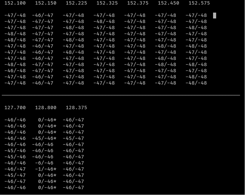
From their wiki: you will see simple text waterfalls, one per each configured channel. This is an example for three devices running in multichannel mode. The meaning of the fields is as follows:

User interface screenshot
  • The number at the top of each waterfall is the channel frequency. When running in scan mode, this will be the first one from the list of frequencies to scan.
  • The number before the forward slash is the current signal level
  • The number after the forward slash is the current noise level estimate.
  • If there is an asterisk * after the second number, it means the squelch is currently open.
  • If there is a > or < character after the second number, it means AFC has been configured and is currently correcting the frequency in the respective direction.

Execute the following command to start running in foreground mode:

# Test in foreground mode
/usr/local/bin/rtl_airband -f

Press Cntrl+C to break out of the stream once you are satisfied with your testing.

Enable RTLSDR-Airband to autostart

To enable RTLSDR-Airband to automatically start up each time your Raspberry Pi is rebooted, you can execute the following commands from within the RTLSDR-Airband directory.

sudo cp init.d/rtl_airband.service /etc/systemd/system
sudo chown root:root /etc/systemd/system/rtl_airband.service
sudo systemctl daemon-reload
sudo systemctl enable rtl_airband
sudo systemctl start rtl_airband

Hurray! We are done!

If you made it this far you have completed all the steps! Enjoy your new streaming SDR solution!

Controlling a Haiku fan with a wall switch

TLDR: I wanted to control the light on Big Ass Fans' Haiku fan via physical wall switch, so this tutorial is going to go over how to pair a smart switch with Home Assistant software to provide a traditional light switch experience. Skip down to Setting up the wall switch to start if you want to skip my ramblings.

Here's a YouTube video if you don't like to read:

Longer story

In the background of many commercial buildings, silently lurking and judging us from above, lies what looks like possibly a recycled helicopter blade. Don't be fooled, these blades are no helicopter blade, they are years of engineered excellence in the makings. The company prides themselves on solid engineering and building a solid product for their customers. They are called Big Ass Fans.

For quite some time I've been eyeing their Haiku fan, which is their residential ceiling fan. Their fans look incredibly modern, operate almost completely silent, have a "SenseMe" feature that figures out when people are in the room to automatically do stuff, and they have an API that you can integrate into locally on the fan via WiFi (lose internet, no problem, you can still control your fan!). One of my biggest "beefs" with today's companies is they try to make things really proprietary and crappy, so seeing the company that takes pride in their product and allowing others to integrate into it remotely without internet is super "cool" ๐Ÿ˜‰

You spin me right round

The fan itself is smart... too smart

One thing that's really interesting, is when you hook up the fan, to me, it's designed more like their commercial units where it needs to be constantly powered on; from there you remotely control the fan either by remote or their smart phone application. Both the remote and even the mobile app, work incredibly well and are extremely responsive, but the only tricky thing about the fan is in a residential setting, many folks have light/fan combos in their bedrooms, offices, and living rooms and if a guest walks into the room and flips the light switch, they are flipping power to the whole fan/light.

So....?

In many commercial settings, fans you typically set once and let em' rip, but with the residential play, you have grandparents, guests, friends, etc. that may come over. Since the remote is there, they go, how do I turn the lights on to this room? Unfortunately, there isn't a good answer here other than to put a plate on the wall and force your guests to check out the remote.

I personally find the remote a hassle since I have a small little corridor into one room, so when it's darker in the evenings, you grab the remote on the wall, walk through this dark area, and then aim the remote somewhere at the ceiling to turn it on (this is if you don't forget the remote in the room from before).

So...?

I am a "big fan" of having a smart home, but I want it to be super intuitive to the end user. I design everything to be used as if my grandparent is over and they have no idea what the heck is going on. In this case, I leveraged an open source project called Home Assistant and a Leviton Z-Wave switch to do the magic of controlling the fan like any other fan you'd buy at a big box store. More specifically, I really just needed to control the light on the fan, so this tutorial is going to go over how to control the light from the fan via the switch.

Setting up the wall switch

The first thing you'll need is a smart switch. It can be WiFi, Z-Wave, ZigBee, etc; it doesn't matter specifically what brand (odds are, it'll be compatible (here's the official list)), but you'll need a switch that allows you to control it via the computer or your phone. I used a dimmer switch specifically as the light on the Haiku allows several different levels of brightness.

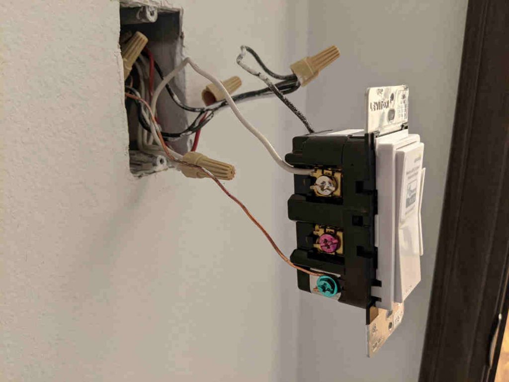
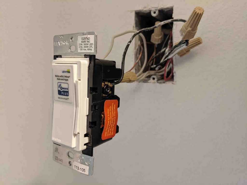
Once you have the switch, what you'll want to do is wire up the fan so it constantly has power and also give power the switch. This does two things: 1) it allows the fan to be powered on regardless if your guest turns the light switch on/off 2) it allows the light switch to stay powered on so you use that to talk to your fan. Here's an example of how I wired my Leviton Z-Wave switch.

Here you can see I don't have anything connected to the red pin, or load. Typically, you'd have this connect back to the fans lights to turn them on/off, but the Haiku fan isn't wired like that.

On this side, you can see we only have the negative wire connected. It's hard to see, but in the box, I have all my neutral and negative wires capped together, which offers power to the fan 100% of the time, regardless of what this switch is doing.

Once you have the switch wired up and ready to go, it should literally do nothing when you turn it on/off, but your fan should stay on all the time.

Setting up Home Assistant Automation

This guide won't go into installing / setting up Home Assistant, rather more so around the automation scripts needed to get this all working. If you are interested in learning more about Home Assistant, you can check out their website here and I have a blog post on how to deploy Home Assistant on a Raspberry Pi here.

To get this working, you will need a couple of things:

  • Add your smart switch to Home Assistant
  • Install HACS
  • Install Haiku SenseMe Integration
  • Add two automation scripts
    • One to control light on/off events
    • One to control light brightness events
Add your smart switch

I won't go into details here too much since every switch will have a separate way to install (Z-Wave vs WiFi vs Zigbee for example), but here is a nice YouTube video on how to get things going (https://youtu.be/FtWFSuMdiSQ?t=353).

HACS

If you have used Home Assistant, it comes with many different native integrations out of the box. Unfortunately, many integrations are developed so quickly the HA (Home Assistant) team doesn't have time to vet them all, so they end up being maintained by the community. HACS helps install these integrations, so I'd recommend installing this.

Step-by-Step documentation on installation can be found here: Prerequisites | HACS

Haiku Integration

A few much smarter folks wrote up an integration for the Haiku fan called SenseME, which we need to install. Once HACS is installed, you can search for the integration via HACS and install the integration. Copied from their integration, here is how to install the integration:

  1. Go to Configuration -> Integrations.
  2. Click on the + ADD INTEGRATION button in the bottom right corner.
  3. Search for and select the SenseME integration.
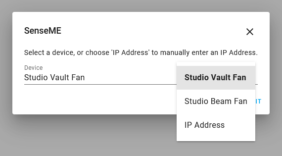
  4. If any devices are discovered you will see the dialog below. Select a discovered device and click Submit and you are done. If you would prefer to add a device by IP address select that option, click Submit, and you will be presented with the dialog in step 5.
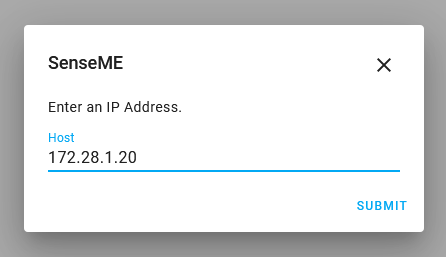
  5. If no devices were discovered or you selected the IP Address option the dialog below is presented. Here you can type in an IP address of undiscoverable devices.
  6. Repeat these steps for each device you wish to add.

Information on the SenseME integration can be found on their GitHub site here: mikelawrence/senseme-hacs: Haiku with SenseME fan integration for Home Assistant (github.com)

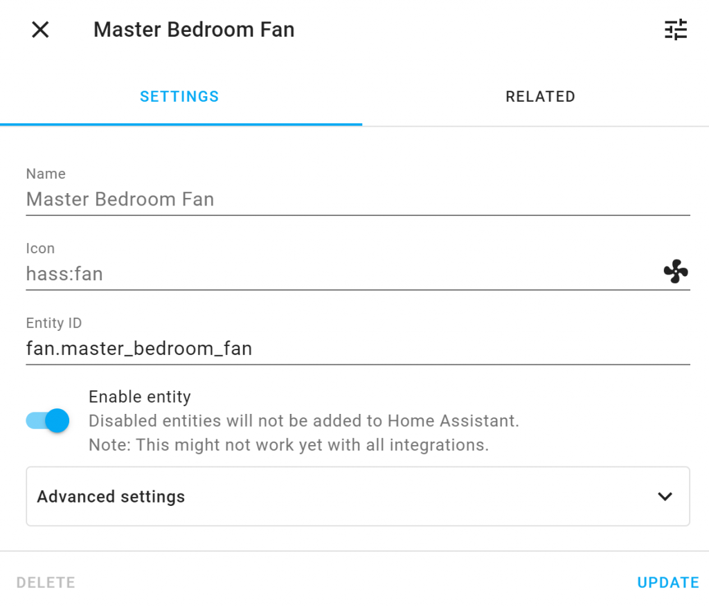
Once configuration is completed, you should see an entity for your fan listed that looks something like this.

On/Off Automation

This automation will first control On/Off behavior from your light switch.

  1. Go to Configuration -> Automations.
  2. Click on the + ADD Automation button in the bottom right corner.
  3. Click the START WITH AN EMPTY AUTOMATION button
  4. Click on the three dots in the top right corner and click Edit in YAML

5. Paste the following code; make sure you edit the names of each of your light switch entities (one for your fan light and one for the light switch on the wall):
light.your_light (the light for your wall) and light.fan_light (the light on the Haiku fan).

alias: Turn On/Off Haiku Fan/Wall Switch
description: ''
trigger:
  - platform: state
    entity_id: light.your_light, light.fan_light
    from: 'off'
    to: 'on'
  - platform: state
    from: 'on'
    to: 'off'
    entity_id: light.your_light, light.fan_light
condition: []
action:
  - service: light.turn_{{ trigger.to_state.state }}
    data:
      entity_id: |-
        {% if trigger.entity_id == 'light.your_light' %}
          light.fan_light
        {% elif trigger.entity_id == 'light.fan_light' %}
          light.your_light
        {% endif %}
mode: single

6. Click the SAVE button

Brightness Automation

This automation will first control On/Off behavior from your light switch.

  1. Go to Configuration -> Automations.
  2. Click on the + ADD Automation button in the bottom right corner.
  3. Click the START WITH AN EMPTY AUTOMATION button
  4. Click on the three dots in the top right corner and click Edit in YAML
  5. Paste the following code; make sure you edit the names of each of your light switch entities (one for your fan light and one for the light switch on the wall):
    light.your_light (the light for your wall) and light.fan_light (the light on the Haiku fan).
alias: Sync Haiku Fan/Wall Switch Brightness
description: ''
trigger:
  - platform: state
    entity_id: light.your_light, light.fan_light
    attribute: brightness
    for: '00:00:02'
condition:
  - condition: template
    value_template: '{{ trigger.to_state.attributes.brightness > 0}}'
action:
  - service: light.turn_on
    data:
      brightness: '{{ trigger.to_state.attributes.brightness }}'
      entity_id: |-
        {% if trigger.entity_id == 'light.your_light' %}
          light.fan_light
        {% elif trigger.entity_id == 'light.fan_light' %}
          light.your_light
        {% endif %}
mode: restart

6. Click the SAVE button

Testing!

At this point, whether you use your remote or the light switch, your lights should be in sync! Use the remote or the wall switch to the turn on/off the lights. Try using the switch to dim and it should adjust the brightness of the light (note: there may be a tiny delay after you make changes to the dimmer value as there's a 2second delay in the automation, which prevents the lights from going wonky).

Conclusion

Through the use of Home Assistant + any smart switch, we can easily control the Haiku fan with physical nobs and dials. While this tutorial only covers controlling the fan's light via a switch, the same principals can be used to add a second switch to control the fan speed.

For those that like physical knobs and dials to control your devices, hope this was helpful!

If you are thinking of buying a Big Ass Fan, please consider using my referral code so I can use them towards future reviews! https://bigassfans.referralrock.com/l/1JACKSTROMB57/

How to update Z-Wave JS Docker Container

This document is written to help those that are using Z-Wave JS and Home Assistant as Docker containers. This tutorial goes hand-in-hand with this: How to update Home Assistant Docker Container | Jack Stromberg

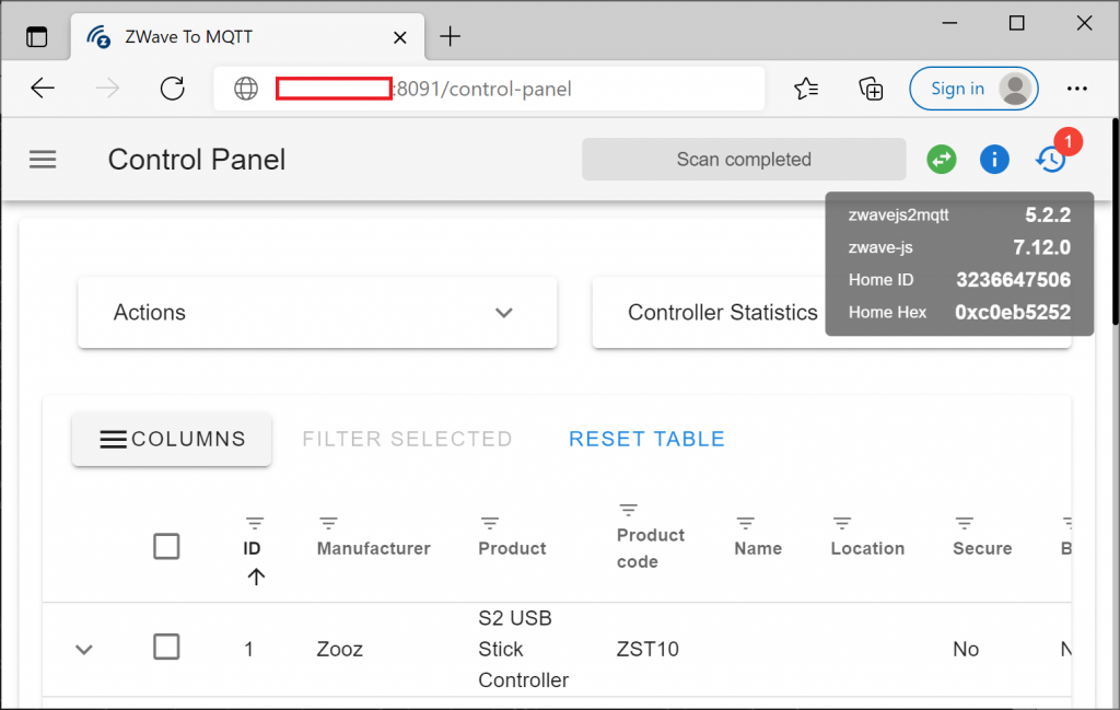
Validate your current version

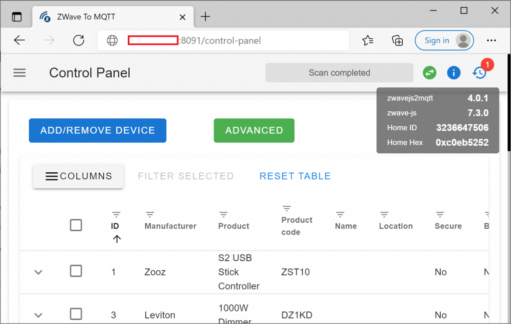
First, validate what version of Z-Wave JS you are running. To do this, navigate to the Z-Wave JS webpage and hover over the i icon to validate what versions of the software you are running. The Z-Wave JS webpage can typically be accessed at http://yourip:8091.

Get the current name of your container and version

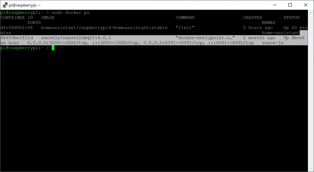
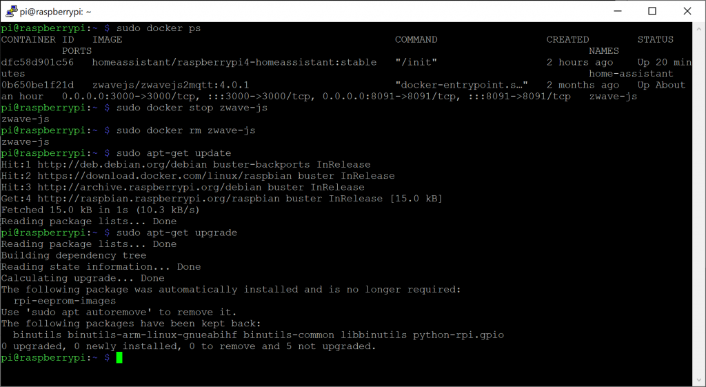
sudo docker ps

In running this command, note the NAME of your container as well as the IMAGE.

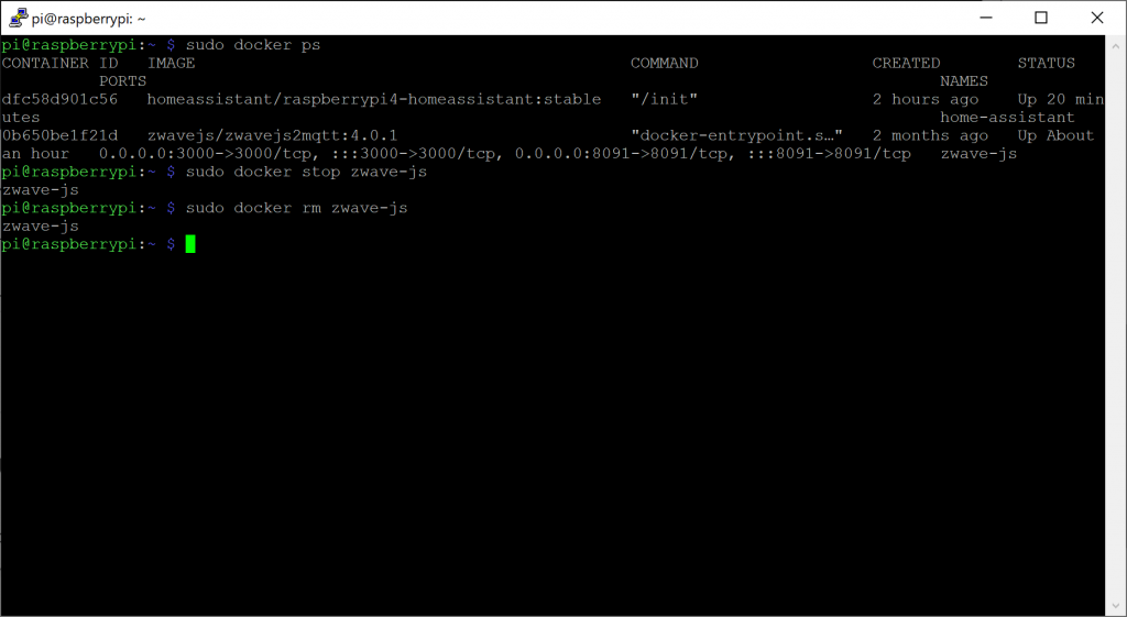
Stop and delete the container

Replace the name of the container in the command below with the value you had.

sudo docker stop zwave-js
sudo docker rm zwave-js

Update packages

Some versions of HA require newer versions of Python, Docker, etc. I may consider updating to latest package versions first.

sudo apt-get update
sudo apt-get upgrade

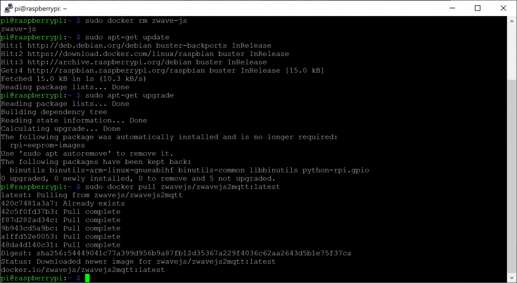
Pull the latest container from Docker Hub

Replace the value below with your IMAGE value you documented in the previous steps.

sudo docker pull zwavejs/zwavejs2mqtt:latest

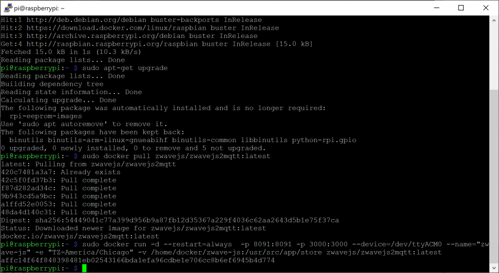
Deploy the container

Make sure your replace the name and value of the image with the values in the previous step. In addition, ensure you specify the correct path to where you existing configuration files exist to have the container load your existing configurations.

sudo docker run -d --restart=always  -p 8091:8091 -p 3000:3000 --device=/dev/ttyACM0 --name="zwave-js" -e "TZ=America/Chicago" -v /home/docker/zwave-js:/usr/src/app/store zwavejs/zwavejs2mqtt:latest

Validate your version number

After a few minutes, navigate back to the Z-Wave JS page. Upon load, you should now be on the latest versions.

Notes:

You can find the latest, stable, and development builds out on docker hub here: https://hub.docker.com/r/zwavejs/zwavejs2mqtt

How to add buster-backports to a Raspberry Pi

What are backports?

Debian has a really good write up here on what backports are. Copying directly from their introduction paragraph:

You are running Debian stable, because you prefer the Debian stable tree. It runs great, there is just one problem: the software is a little bit outdated compared to other distributions. This is where backports come in.

Backports are packages taken from the next Debian release (called "testing"), adjusted and recompiled for usage on Debian stable. Because the package is also present in the next Debian release, you can easily upgrade your stable+backports system once the next Debian release comes out. (In a few cases, usually for security updates, backports are also created from the Debian unstable distribution.)

Backports cannot be tested as extensively as Debian stable, and backports are provided on an as-is basis, with risk of incompatibilities with other components in Debian stable. Use with care!

It is therefore recommended to only select single backported packages that fit your needs, and not use all available backports.

Once I enable backports will all packages use them?

No! Any new packages and updates to existing stable packages will prefer the stable releases. The only time you will leverage a new backport package is if you explicitly specify to pull from them.

How do I enable backports?

First you need to add the new backport source to your sources.list file. Edit the file in vi:

sudo vi /etc/apt/sources.list

Arrow down to the last row, press o to create a new line and then enter the following:

deb http://deb.debian.org/debian buster-backports main

Press escape and then type :wq to save the changes and exit via.

Next, we need to specify a keyserver to verify the authenticity of these packages. Note we use Ubuntu's key servers to validate the packages. Interestingly, Debian has a keyring to validate the packages, however the keyring doesn't contain the backports for buster on the raspberry pi at time of writing this. Ubuntu's servers will work fine to validate the authenticity of these packages and you will ultimately pull the packages from Debian rather than Ubuntu.

sudo bash
gpg --keyserver keyserver.ubuntu.com --recv-keys 04EE7237B7D453EC
gpg --keyserver keyserver.ubuntu.com --recv-keys 648ACFD622F3D138

gpg --export 04EE7237B7D453EC | sudo apt-key add -
gpg --export 648ACFD622F3D138 | sudo apt-key add -
exit

How do I obtain a package from backport?

You can leverage one of the follow formats to specify the backport package:

apt install <package>/buster-backports
apt-get install <package>/buster-backports

or

apt install -t buster-backports <package>
apt-get install -t buster-backports <package>

or

aptitude install <package>/buster-backports