Category Archives: Networking

Networking Stuff!

Establishing a GCP VPN Tunnel to Azure Virtual WAN; Active/Active BPG Configuration

This is a quick reflection of the steps I took to establish two IPSec tunnels between GCP’s VPC and Azure’s Virtual WAN VPN Gateway, propagating routes dynamically via BPG and ensuring High Availability. The design is fairly straightforward since both GCP and Azure offer the ability to established multiple connections to remote peers. When everything is said and done, you’ll end up with a diagram that conceptually looks something like this:

Note: It is recommended to complete the steps in this document in the outlined order to complete the least amount of steps. In this case, provide Azure Virtual WAN first, then configure GCP, then create the Azure Virtual WAN Site Links / Connections to GCP.

Note 2: If you have followed my previous guide on establishing an AWS VPN tunnel to Azure Virtual WAN , this guide will co-exist both connections and can skip the Create Azure Virtual WAN and Virtual WAN Hub sections.

Create Azure Virtual WAN and Virtual WAN Hub

On the Azure side, first we need to create a Virtual WAN resource and a Virtual WAN Hub, which will contain our VPN Gateway. If you have already created these, you can skip to the next session.

First, click the "Hamburger" icon and select Create a resource

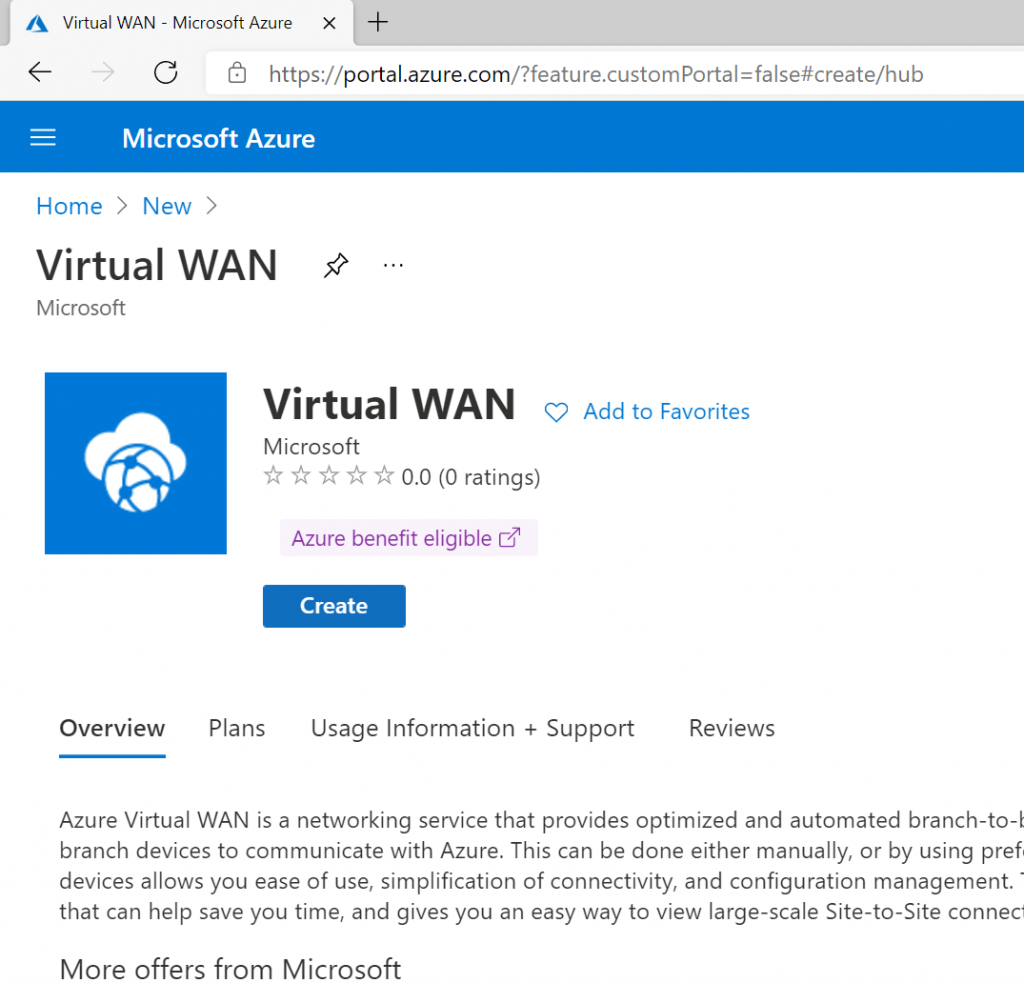
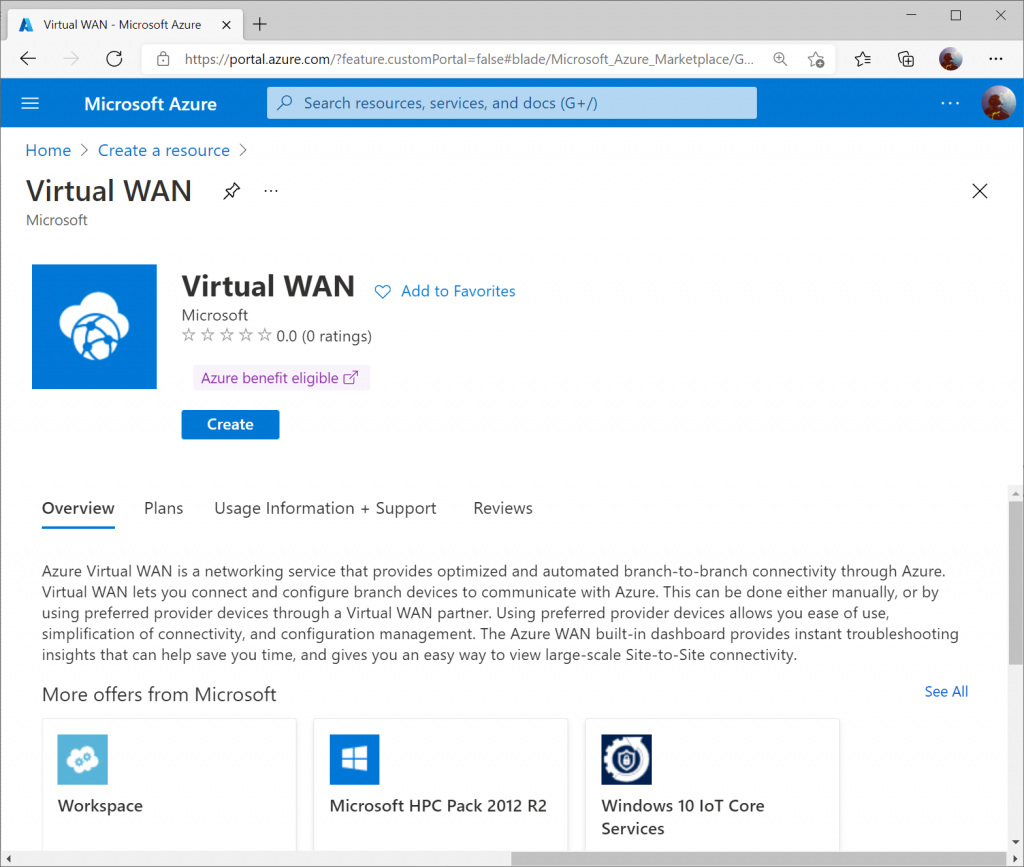
Search for Virtual WAN and select it from the list in the marketplace.
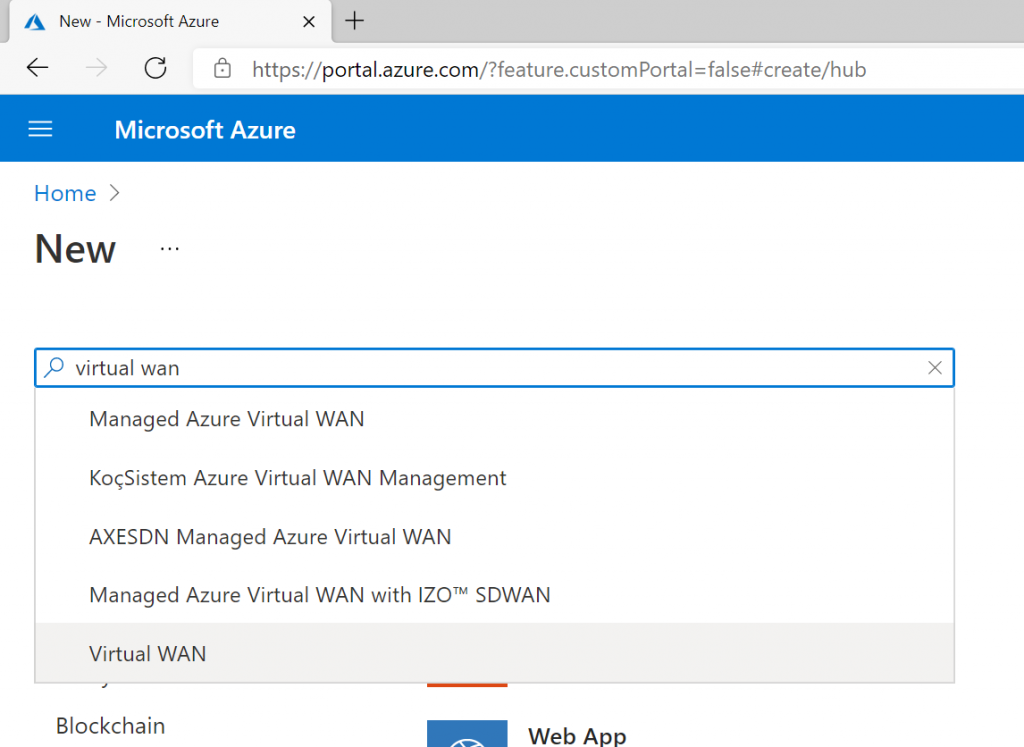
Select Create
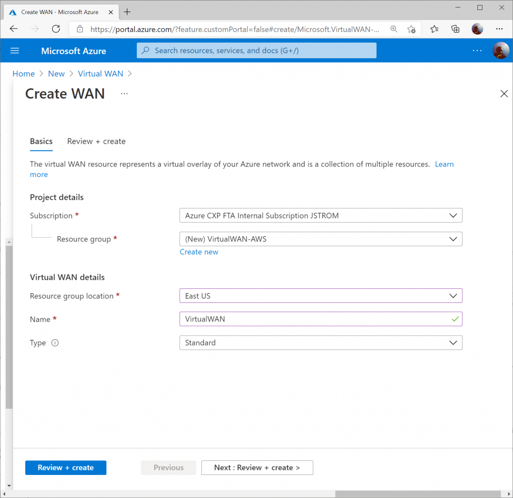
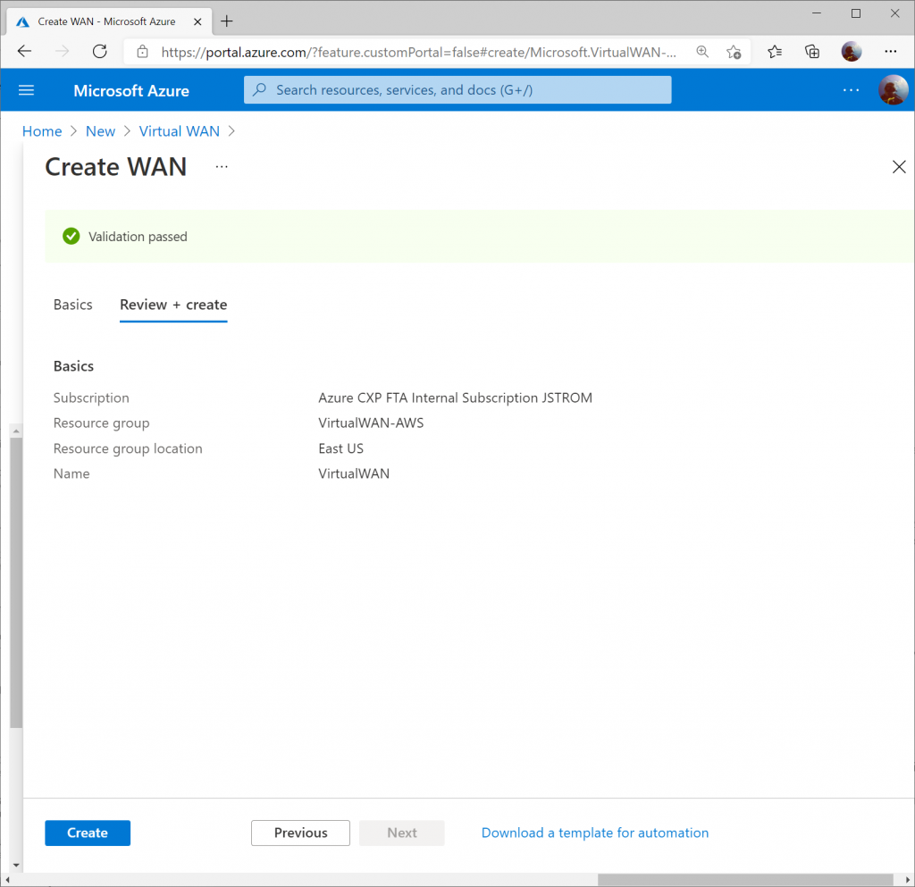
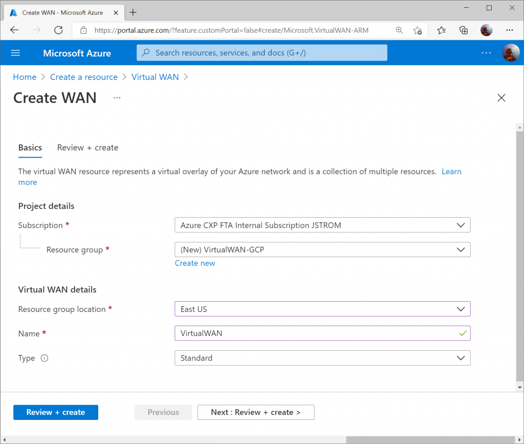
Specify the resource group and region you wish to deploy the Virtual WAN resource to. Specify a name for your Virtual WAN resource and click Review + Create
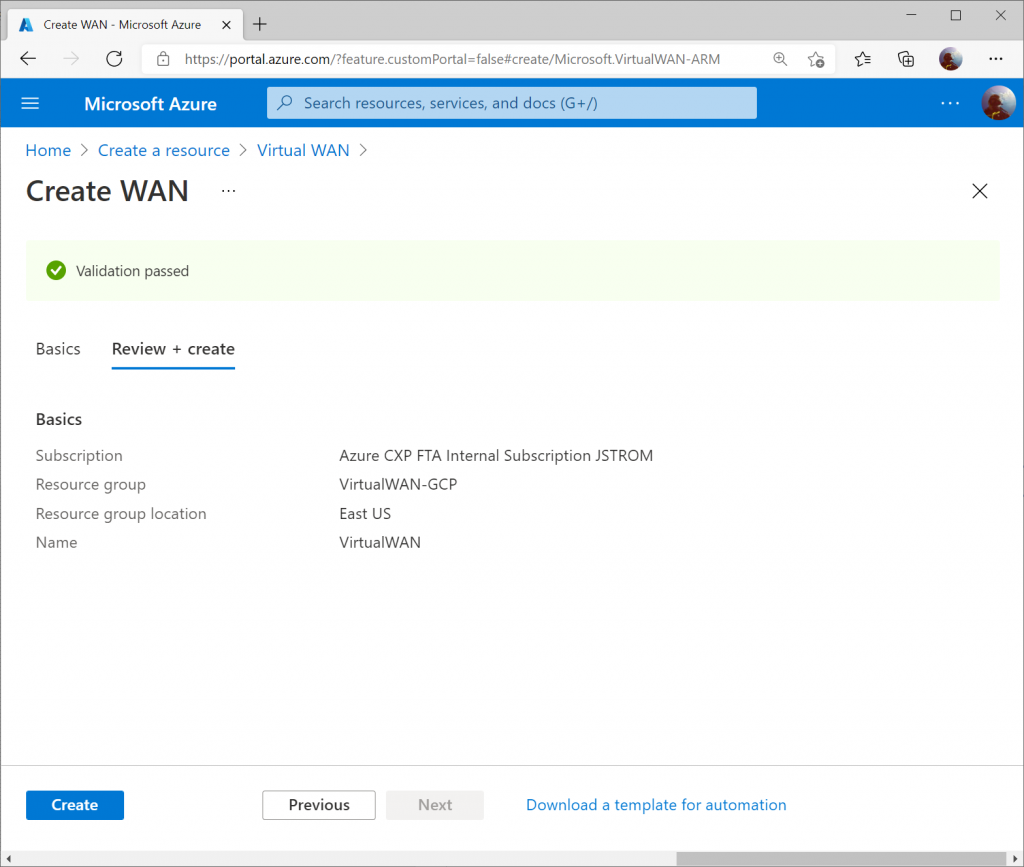
Click Create to start provisioning the Virtual WAN resource.
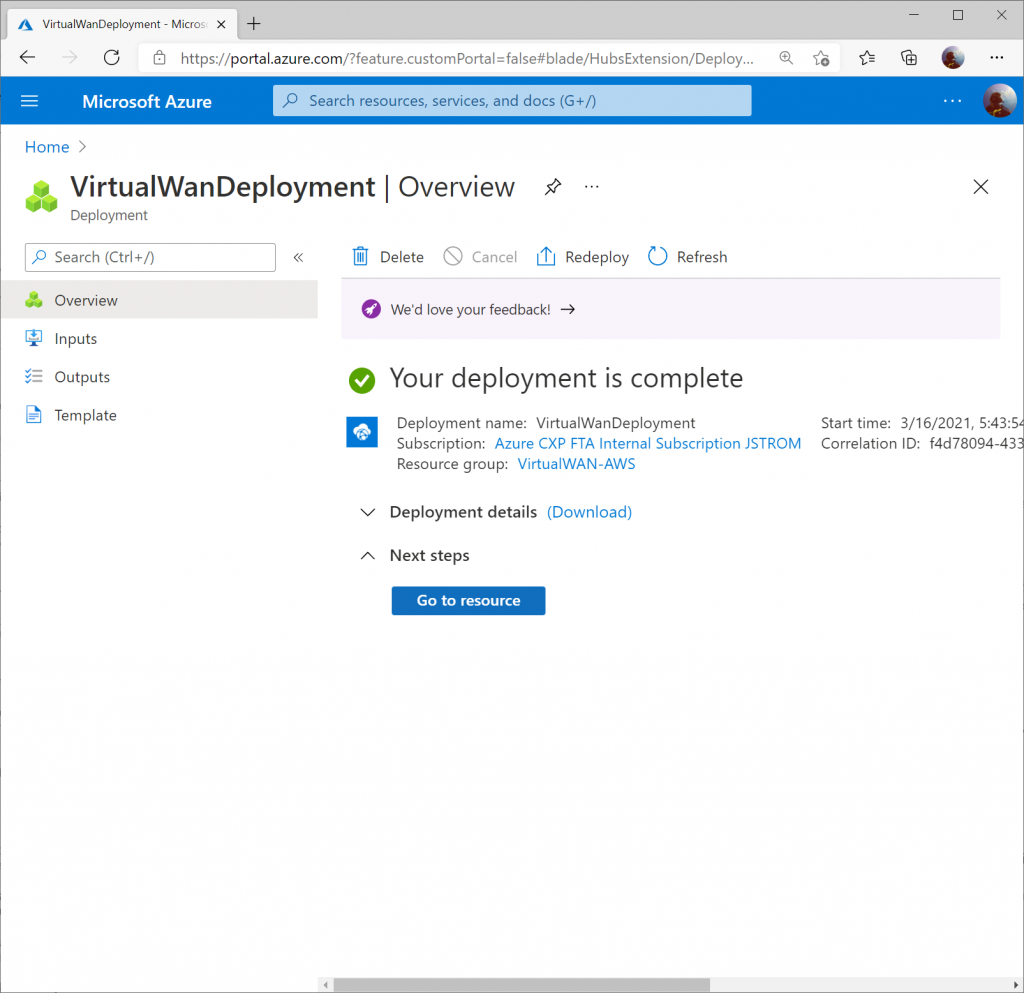
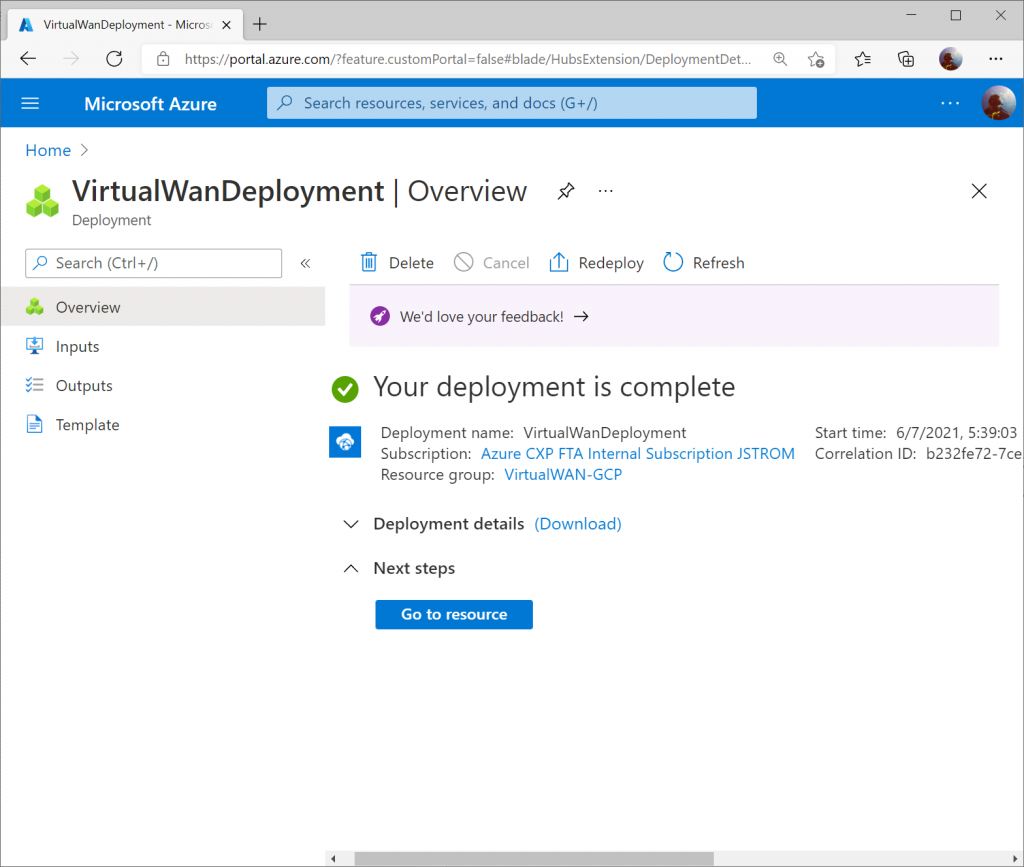
Once the resource is created, click Go to resource to navigate to your Virtual WAN resource.
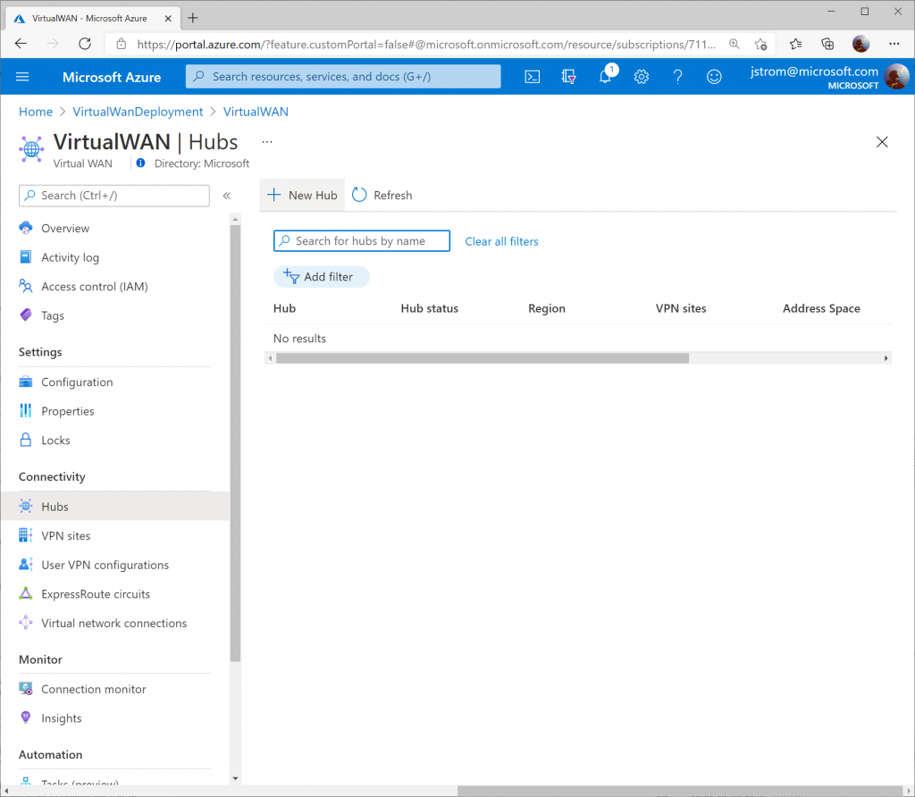
On the Virtual WAN resource, select New Hub from the top menu.
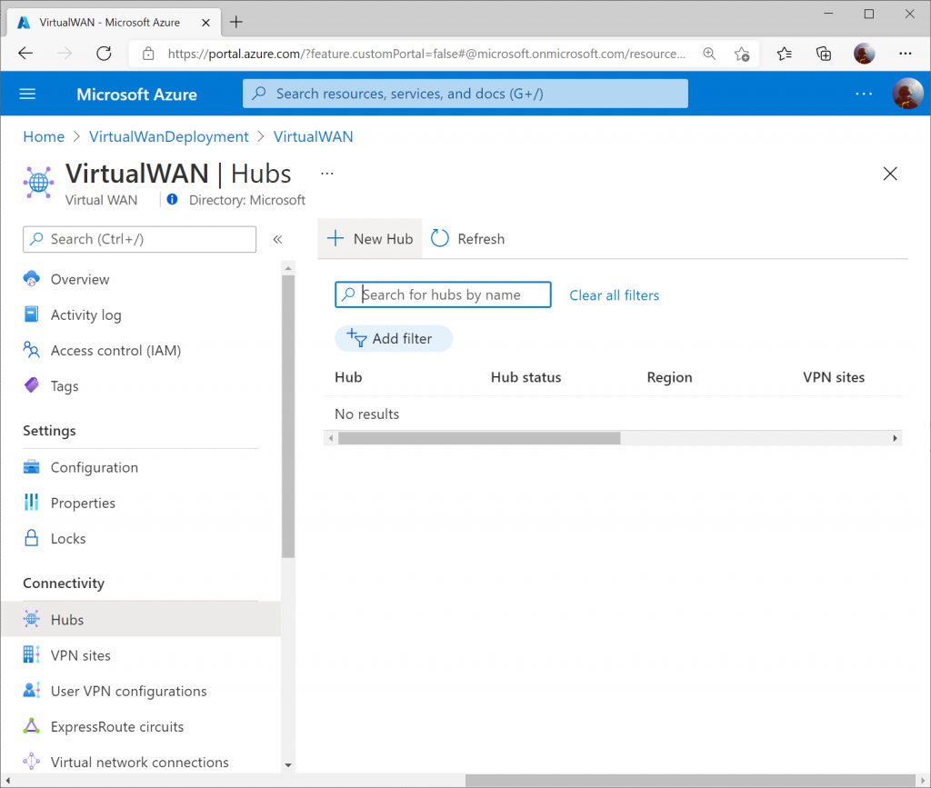
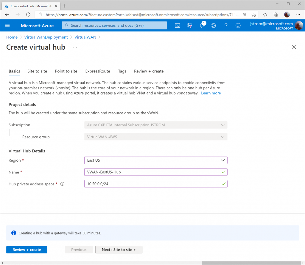
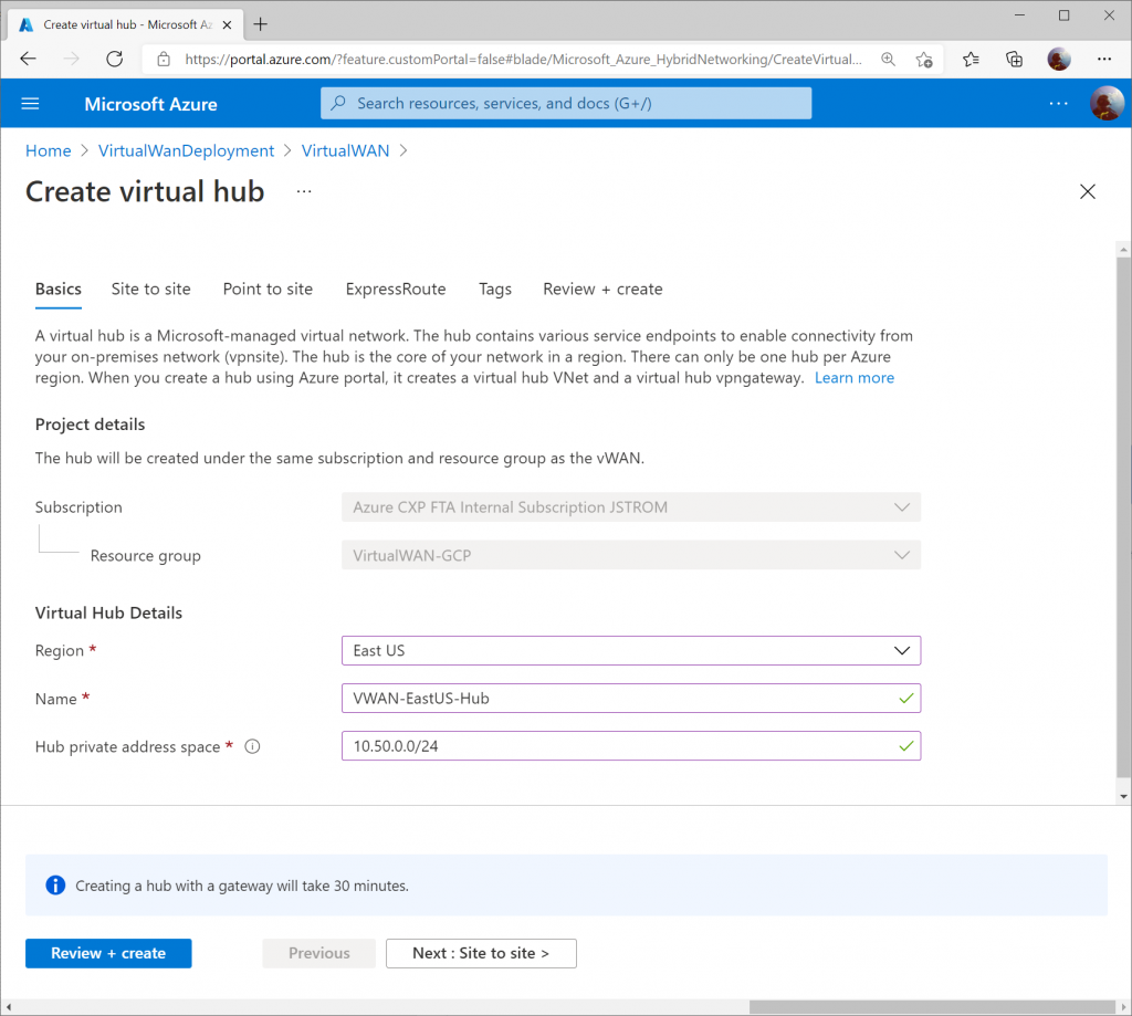
Specify the name of the Hub and an address space that can be used for all the networking components Virtual WAN will deploy into the Virtual Hub. Click Next : Site to Site >
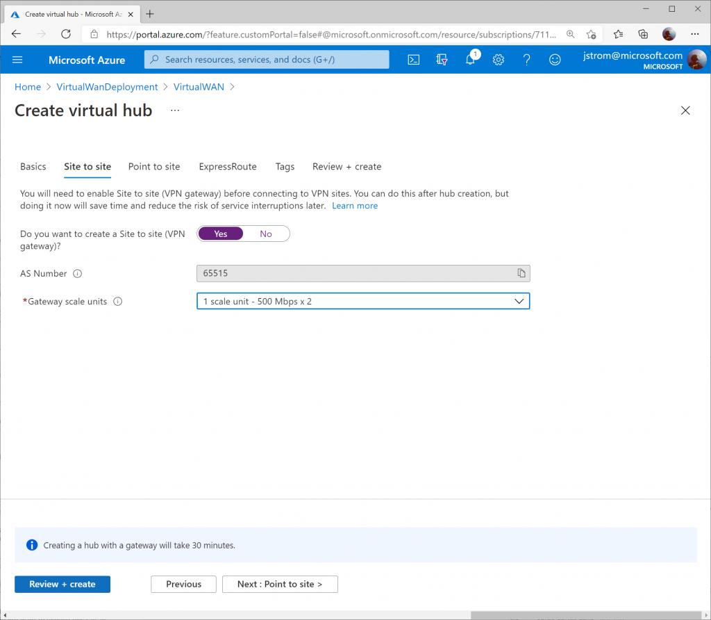
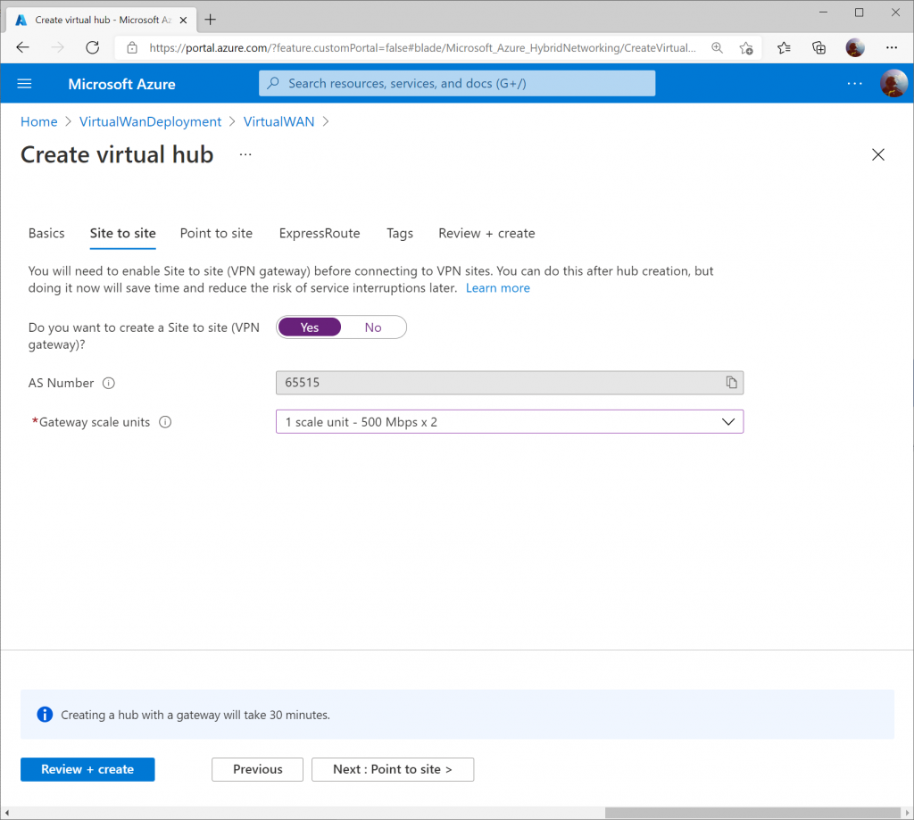
On the Site to Site tab, toggle Yes that you want to provision a VPN Gateway, and specify the scale units you need. Click the Review + create button when done.
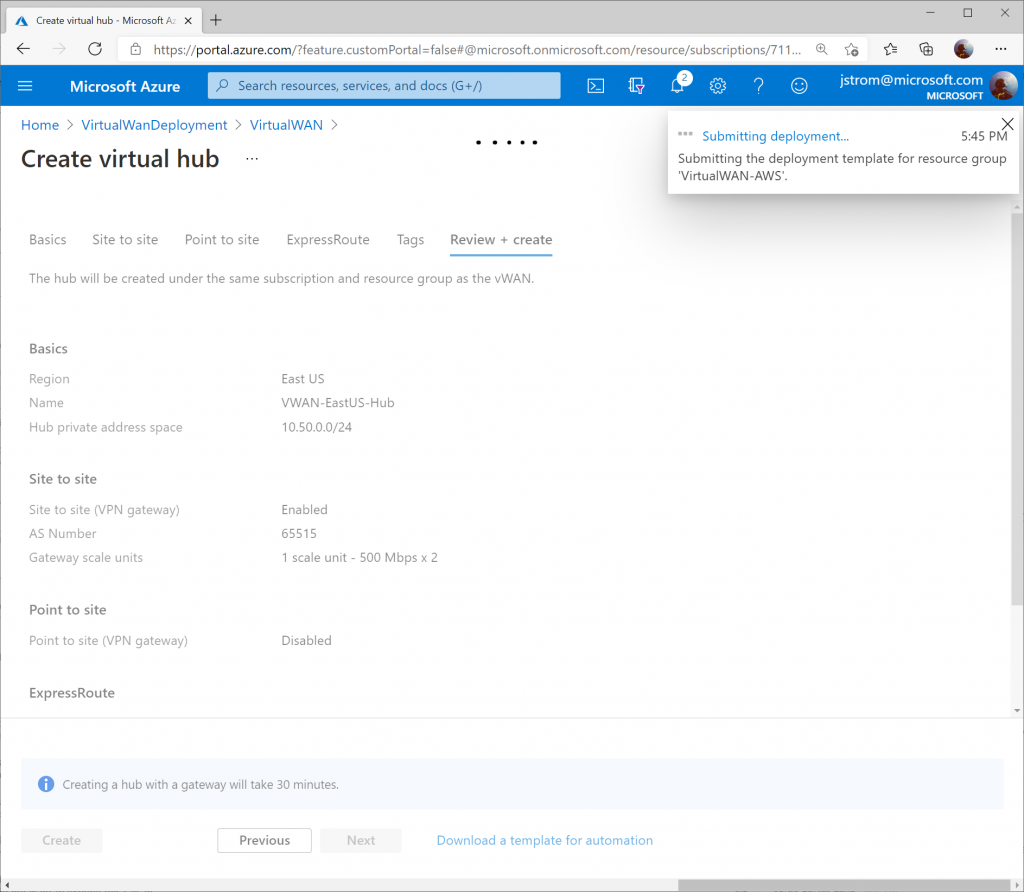
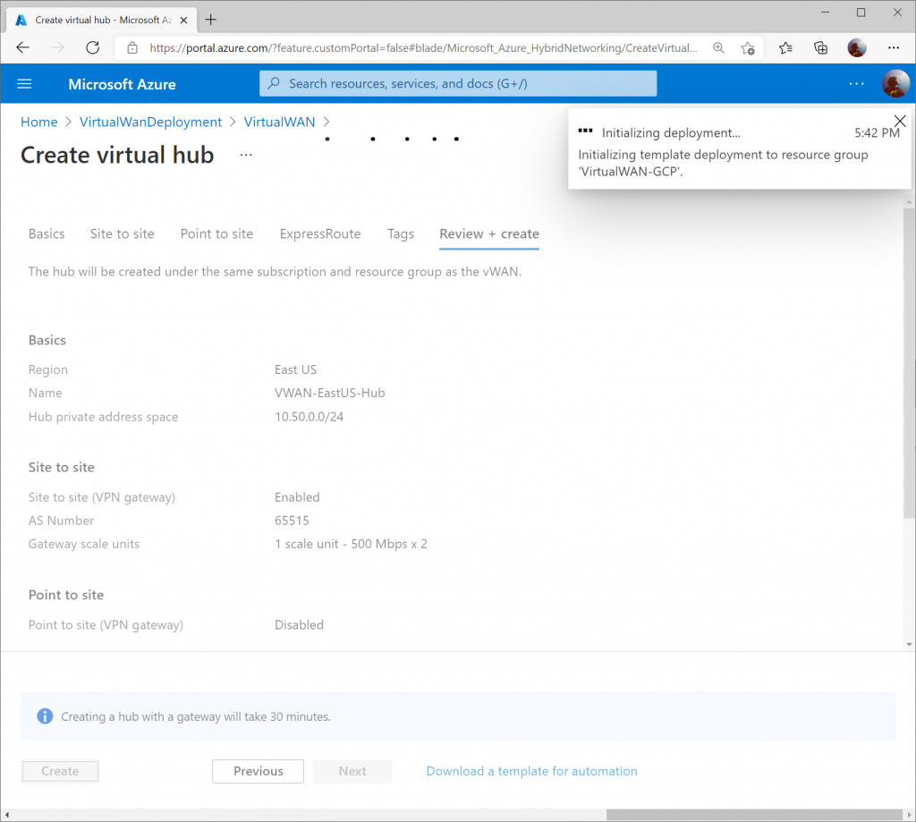
Click the Create button to start provisioning the Hub and VPN Gateway. Please note this can take up to 30 minutes to complete.
Once the Virtual WAN Hub has been created, click the Menu icon and select All services (note: if you click the Go to resource button after the Virtual WAN Hub resource is created, it'll take you the properties of the Hub, which isn't where we want to be).

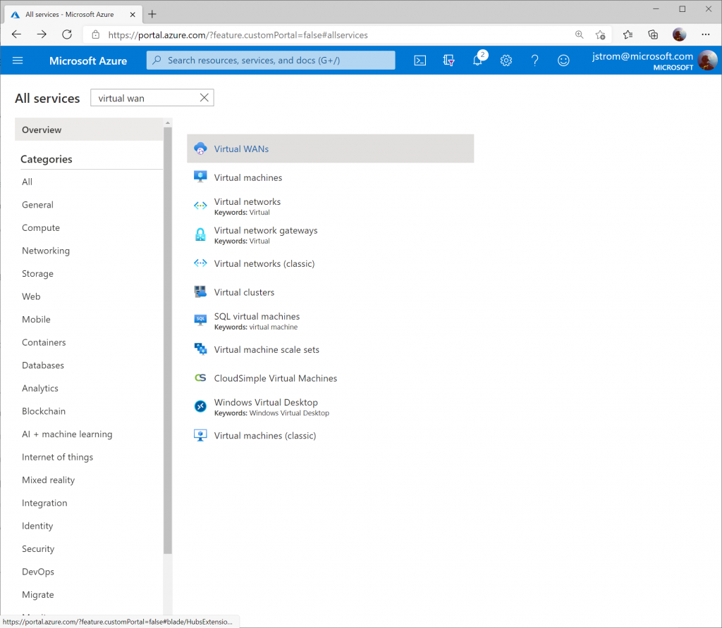
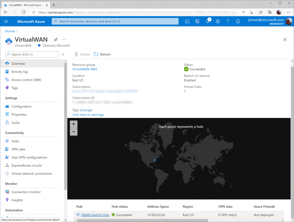
Search for Virtual WAN and select Virtual WANs.
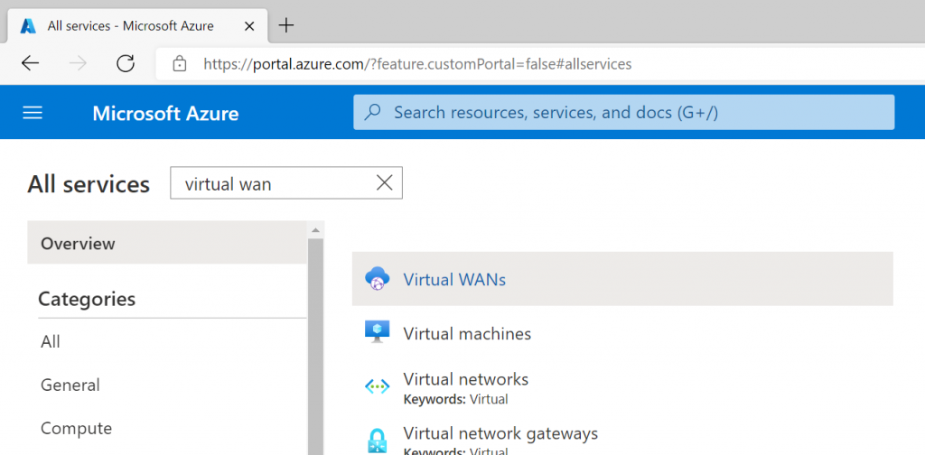
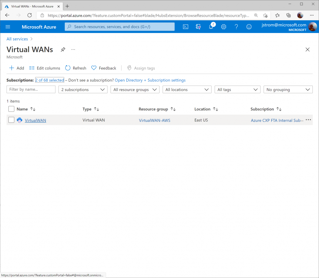
Select your Virtual WAN resource.
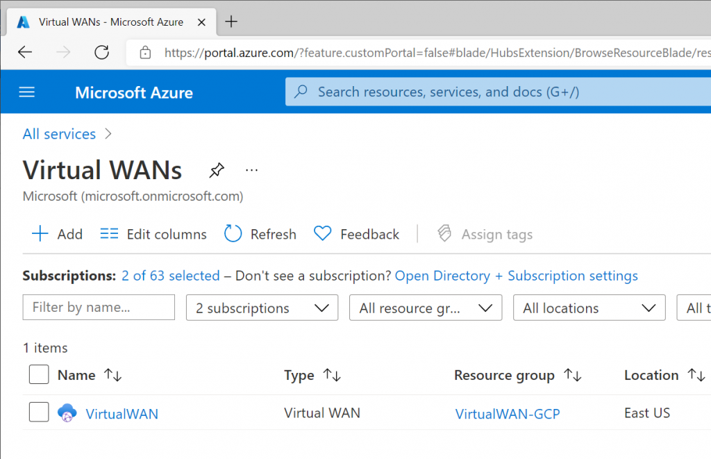
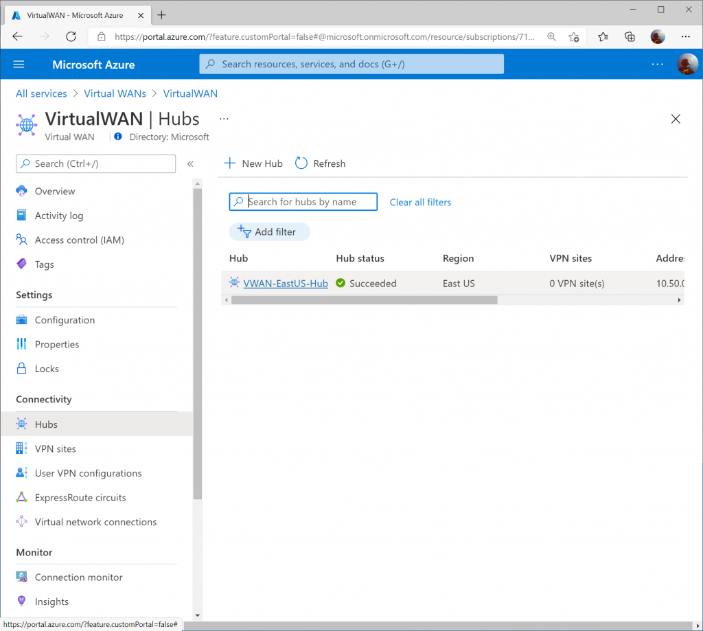
Click on Hubs under Connectivity and select your Virtual WAN Hub.
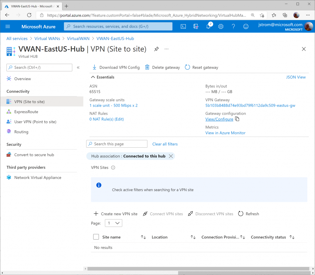
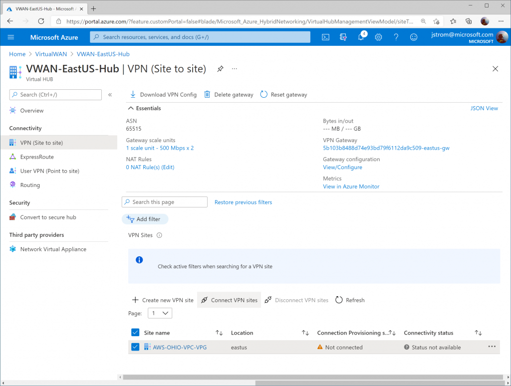
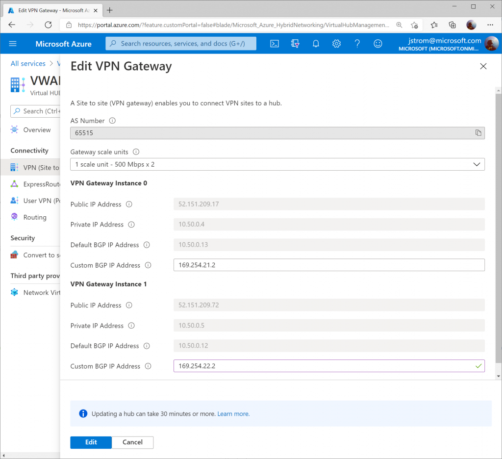
Select VPN (Site to Site) under Connectivity and then click on the View/Configure link.
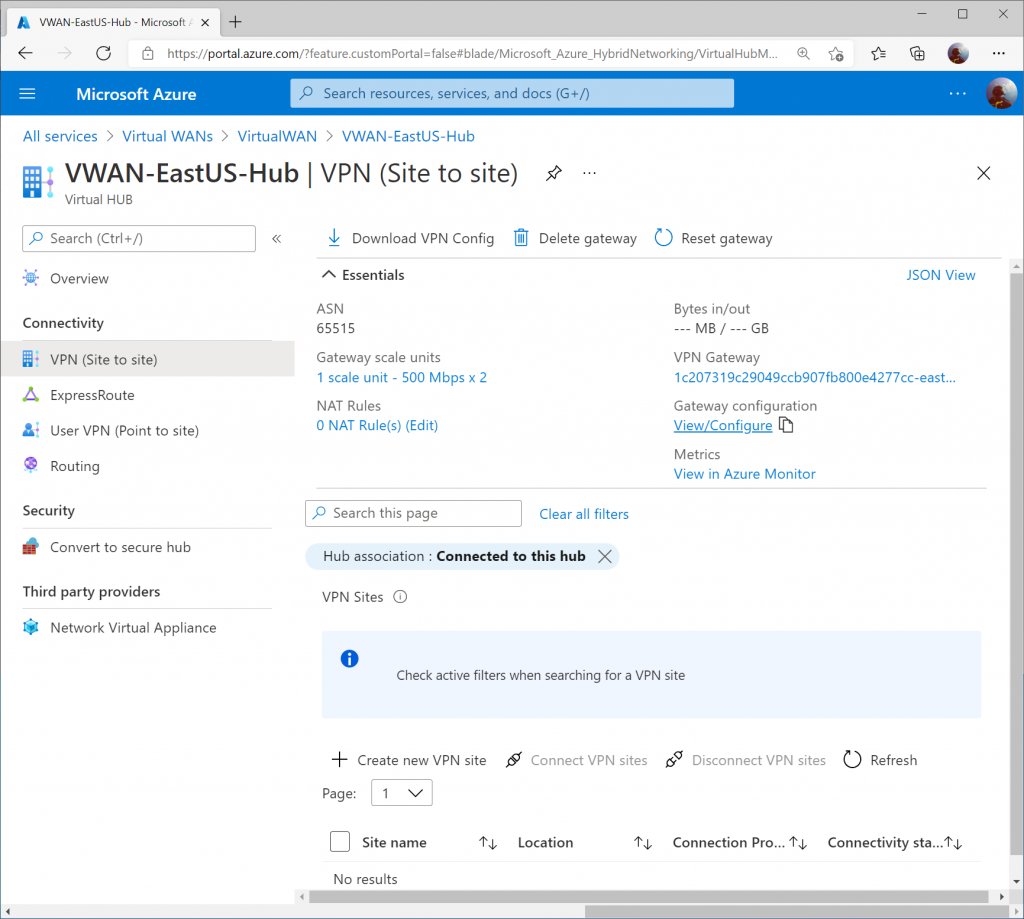
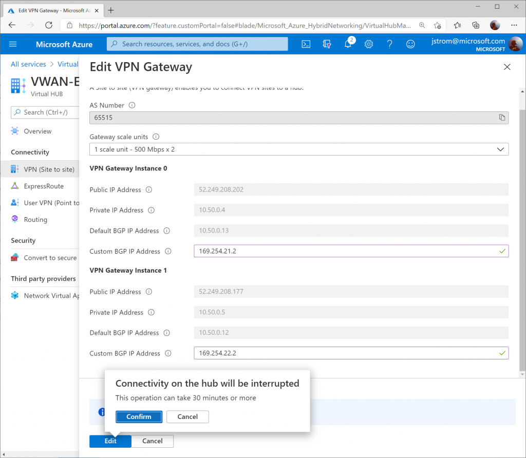
Set the Custom BGP IP addresses for each instance. Use the values below:

  • VPN Gateway Instance 0: 169.254.21.2
  • VPN Gateway Instance 1: 169.254.22.2

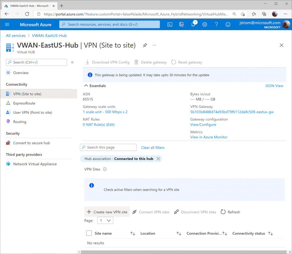
Click Edit once completed.
Configure GCP

Prerequisites

This guide assumes you have a VPC already (in my case, mine is called GCP-VPC with an address space of 10.60.0.0/16) and corresponding set of subnets for your servers.

Note: A GCP VPC is the equivalent of a VNet in Azure. One thing that is different between GCP and Azure is that in GCP you do not need to specify a subnet for your Gateways (i.e. “GatewaySubnet”).

Within the GCP Console, select Hybrid Connectivity -> VPN
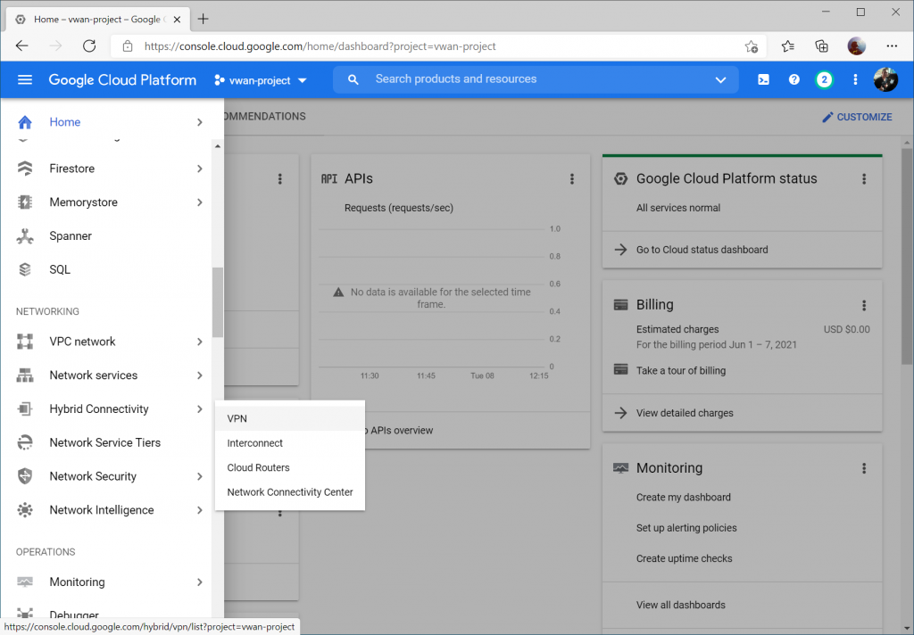
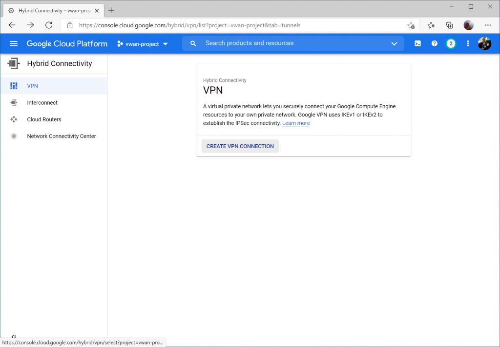
Click Create VPN Connection
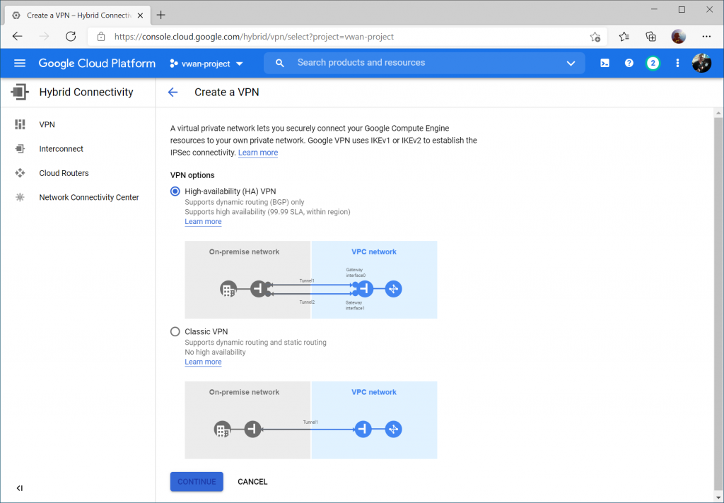
Select High-availability (HA) VPN and select Continue
Enter a name, select your VPC, and specify a region. Click Create & Continue.
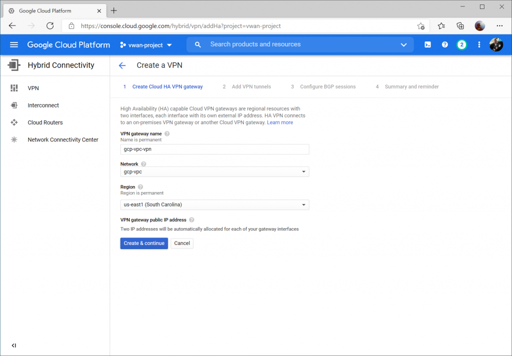
Write down your Interface public IPs (we'll use these later) and check On-prem or Non Google Cloud for Peer VPN Gateway. Click Create & continue.
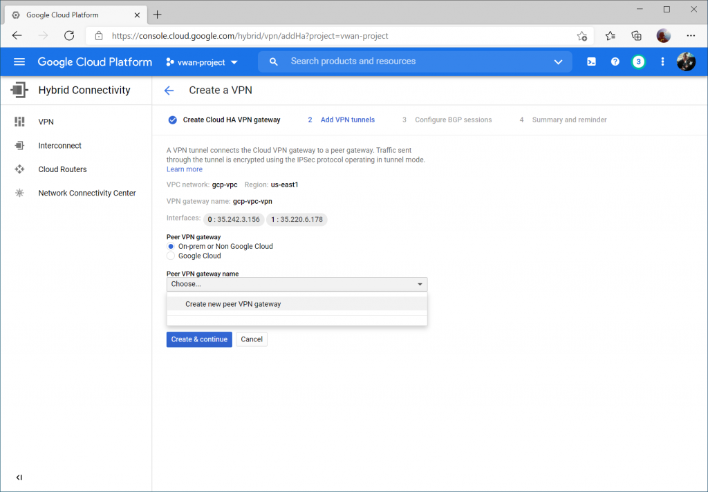
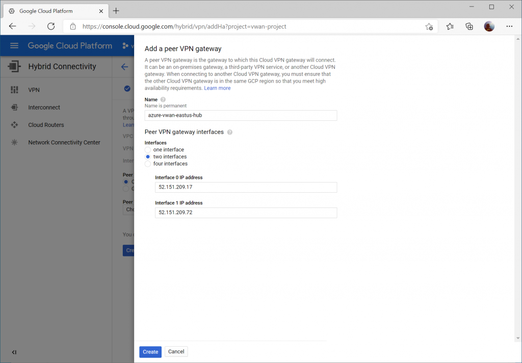
Select two interfaces and enter your Instance 0 and Instance 1 Public IP addresses from your Virtual WAN Hub's VPN Gateway. Click Create.
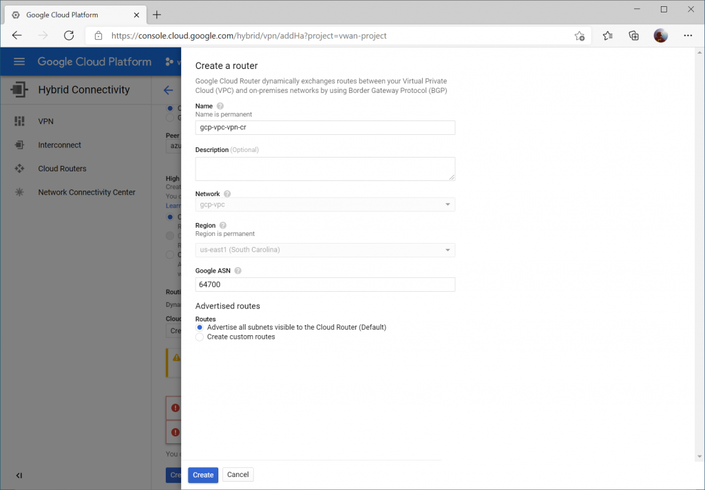
Click the dropdown for Cloud Router and select Create a new router
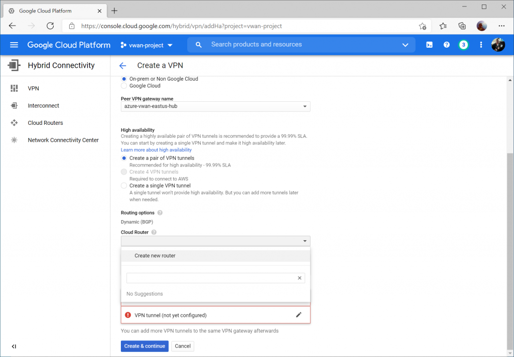
Enter a name and description for your router. For the ASN, enter a unique ASN to use (I used 64700 to differentiate from Azure as well as the ASN I used in the AWS example (which was 64512)). You can specify any supported ASN for this, however I would recommend against using 65515 specifically as this is reserved by Azure's VPN Gateways.

Note: Google ASN must be an integer between 64512 and 65534 or between 4200000000 and 4294967294 or 16550
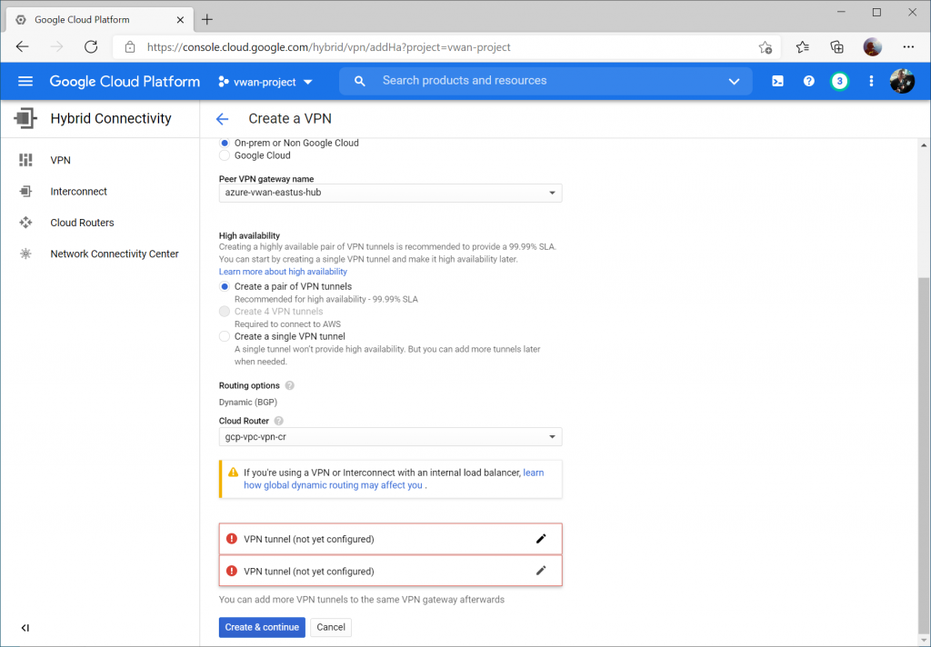
Click the pencil icon to modify the first VPN tunnel.
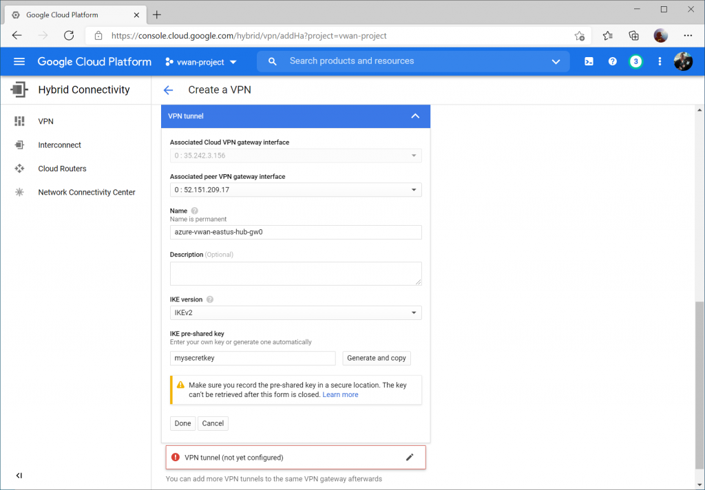
Select the instance 0 VPN Gateway interface, enter a name, set the IKE version to IKEv2, enter a pre-shared key, and click Done.
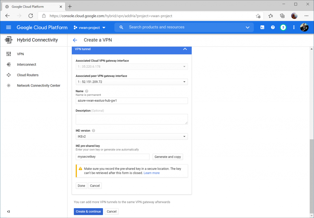
Repeat the same steps for the second VPN tunnel, specifying instance 1 VPN Gateway interface, enter a name, set the IKE version to IKEv2, enter a pre-shared key, and click Done and then Create & continue.
Click the Configure button for the first BPG session.
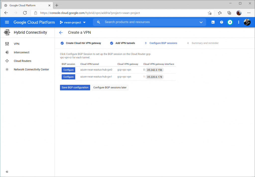
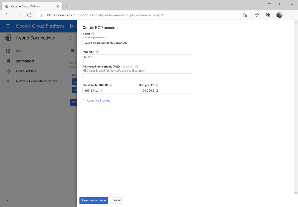
Enter a name for the first BGP peer connecting to instance 0 gateway on Virtual WAN.

Specify Peer ASN of 65515 (this is Azure VWAN's BGP ASN), specify 169.254.21.1 for Cloud Router BGP IP and 169.254.21.2 as BGP peer IP (Azure VWAN's BGP Peer IP). Click the Save and continue button.
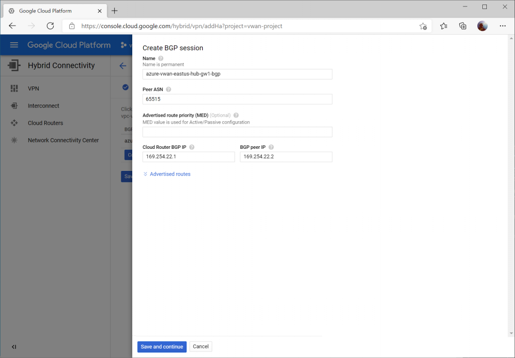
Click the Configure button and enter a name for the first BGP peer connecting to instance 1 gateway on Virtual WAN.

Specify Peer ASN of 65515 (this is Azure VWAN's BGP ASN), specify 169.254.22.1 for Cloud Router BGP IP and 169.254.22.2 as BGP peer IP (Azure VWAN's BGP Peer IP).
Click the Save BGP configuration button.
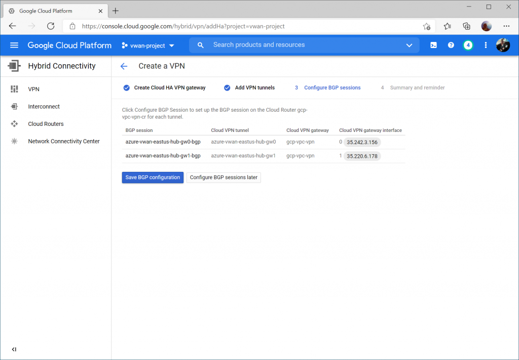
Configure Azure Virtual WAN VPN Site

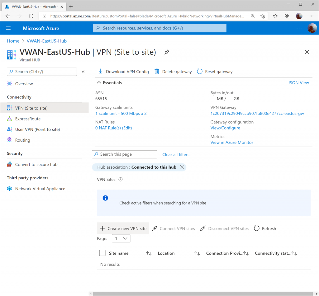
On the Virtual WAN hub, select VPN (Site to site) and click + Create new VPN site
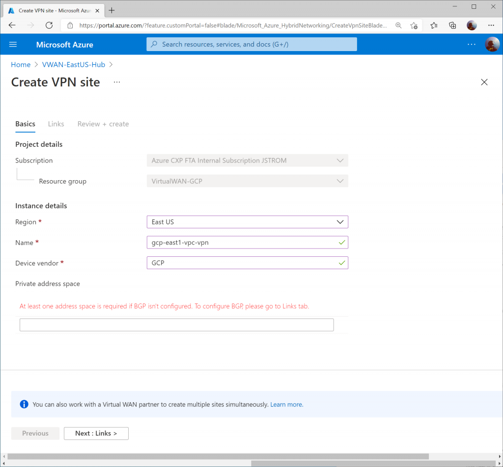
Specify a name for the VPN connection, enter GCP for vendor, and click Next : Links >
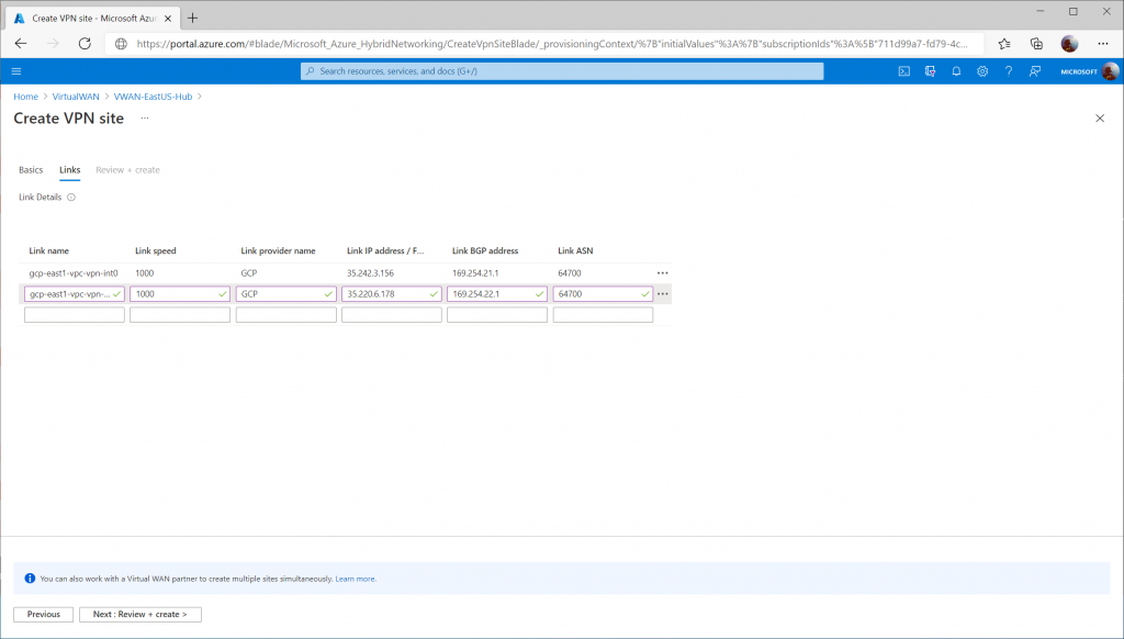
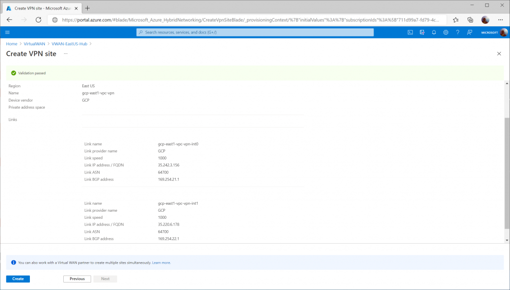
Specify the following values to define each VPN tunnel that should be created to connect to GCP's VPN interfaces.

Note: I entered 1000 for the link speed as a placeholder, but that doesn't mean the connection will be throttled down to 1Gbps.

  • First Link:
    • Link Name: gcp-east1-vpc-vpn-int0
    • Link Speed: 1000
    • Link provider name: GCP
    • Link IP address: <GCP VPN Interface 0 Public IP>
    • Link ASN: 64700
  • Second Link:
    • Link Name: gcp-east1-vpc-vpn-int1
    • Link Speed: 1000
    • Link provider name: GCP
    • Link IP address: <GCP VPN Interface 1 Public IP>
    • Link ASN: 64700

Click Create

Configure Virtual WAN VPN Connection

Once the Virtual WAN Hub has been created, click the Menu icon and select All services.

Search for Virtual WAN and select Virtual WANs.

Select your Virtual WAN resource.

Click on Hubs under Connectivity and select your Virtual WAN Hub.

Select VPN (Site to Site) under Connectivity and then click on the X to remove the Hub association filter.
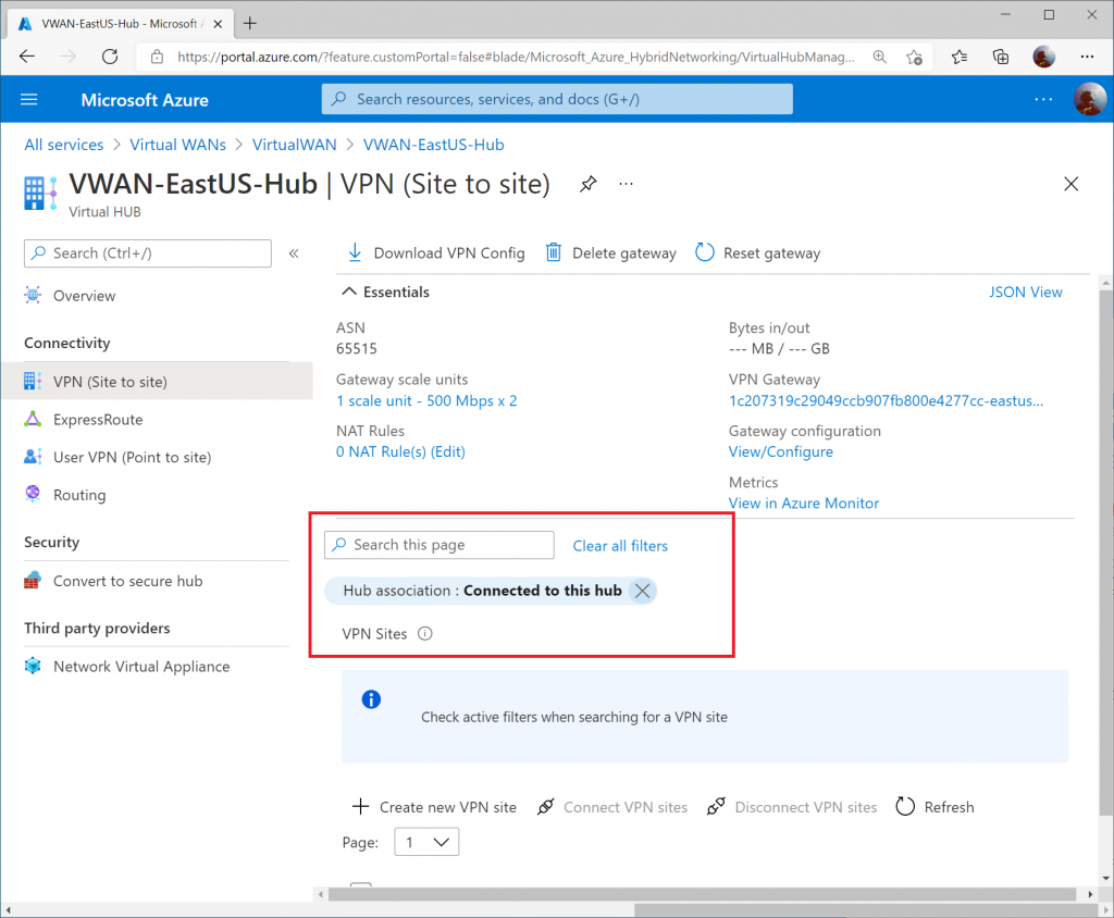
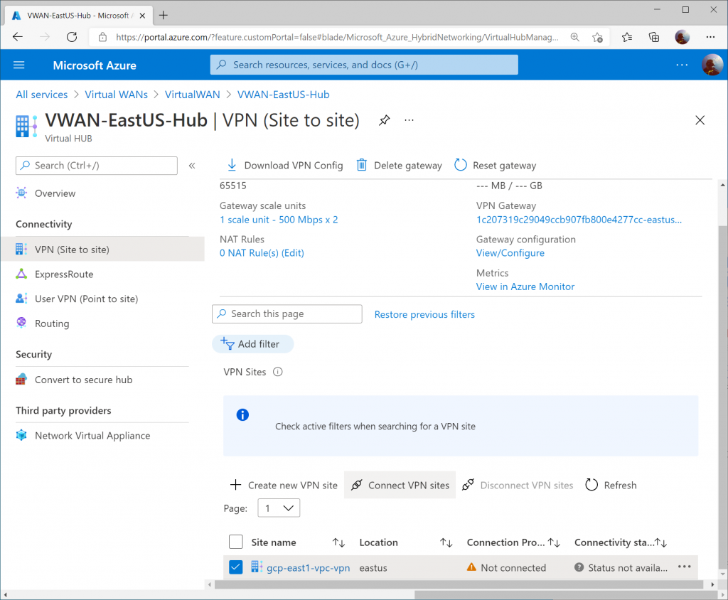
Check the box for your VPN site and click Connect VPN sites
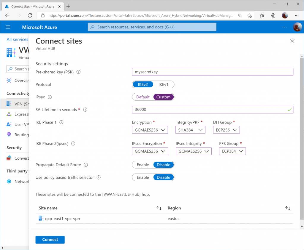
Specify the following information:

  • Pre-shared key (PSK): <use the same one you specified in GCP>
  • Protocol: IKEv2
  • IPsec: Custom
    • SA Lifetime in seconds: 36000
    • Phase 1 (IKE):
      • Encryption: GCMAES256
      • Integrity/PRF: SHA384
      • DH Group: ECP256
    • Phase 2 (IPSec):
      • Encryption: GCMAES256
      • IPSec Integrity: GCMAES256
      • PFS Gropu: ECP384
  • Propagate Default Route: Disable
  • Use policy based traffic selector: Disable

Click Connect.

Note: Here is the link of Supported IKE ciphers for GCP.
Verify Connectivity

From the Azure Side, we will review three different areas to validate connectivity and propagation of routes via BGP.

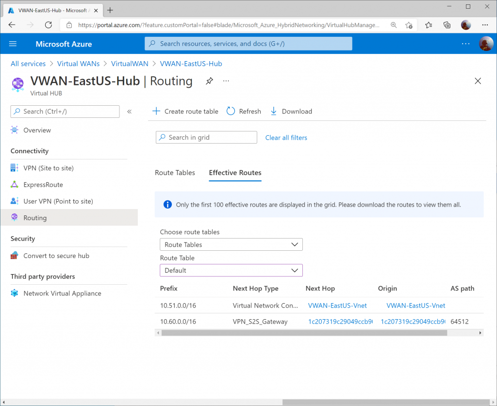
Note: I connected a virtual network to the Virtual WAN Hub to show further configuration. In this case, you'll see an additional IP address space of 10.51.0.0/16, which defines my connected VNet.

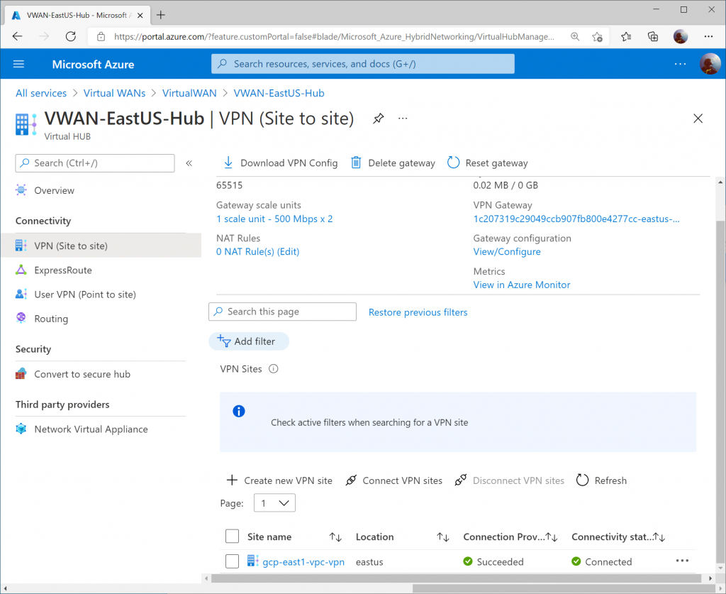
On the Azure Side, you should see the VPN Site’s Connectivity status change to Connected on the VPN (Site to site) blade of your Virtual WAN hub.
On the Routing blade, the Effective Routes will show you the learned VPC address space from GCP (10.60.0.0/16)
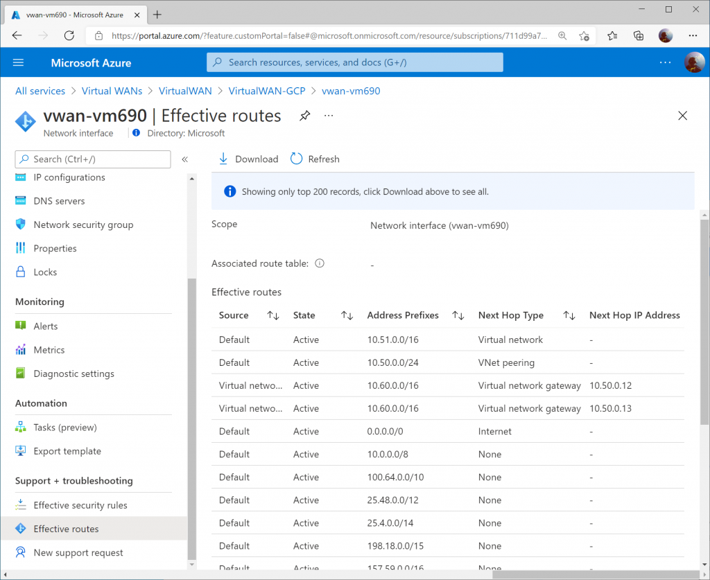
On a virtual machine in a connected VNet to the Virtual WAN Hub, you can pull the Effective Routes. Here I see the 10.60.0.0/16 route learned from both Instance 0 and Instance 1 gateways from the Virtual WAN Hub.
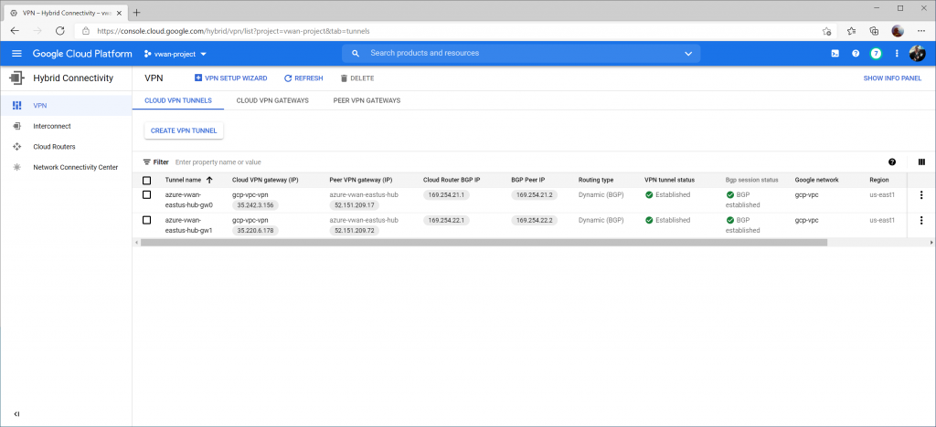
From the GCP Side, we can see the VPN tunnel status as well as Bgp session status now Established and Green on the Hybrid Connectivity -> VPN -> Cloud VPN Tunnels section.
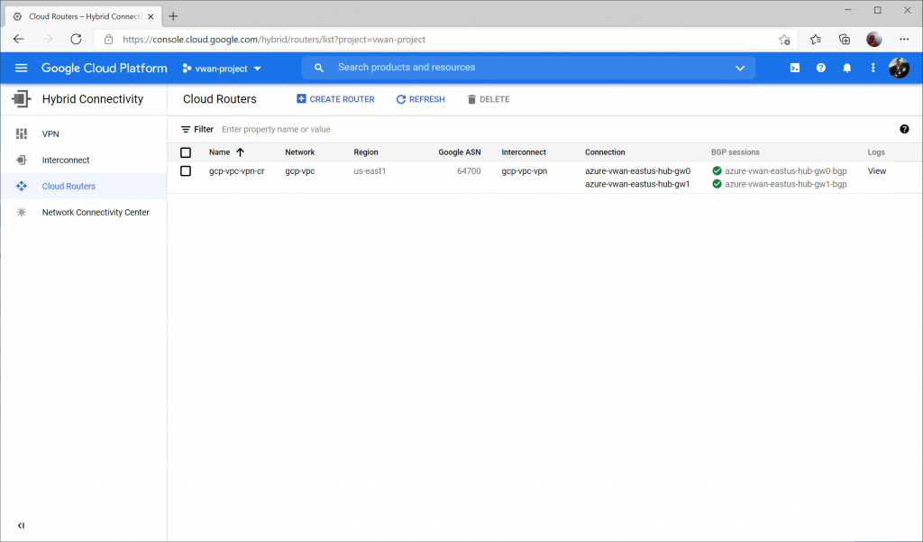
If we switch over to Hybrid Connectivity -> Cloud Routers -> and select View on the logs column
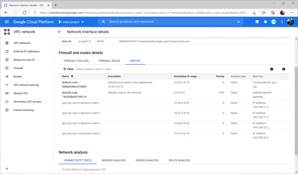
Further, if creating a VM (instance) in GCP, you can view the Firewall and Route details to confirm you see the learned routes from the gateway (in our case, we see 10.51.0.0/16 and 10.50.0.0/24 learned from both BGP Peers):
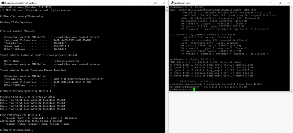
Huzzah! Traffic! 🙂
Establishing an AWS VPN Tunnel to Azure Virtual WAN; Active/Active BPG Configuration

This is a quick reflection of the steps I took to establish two IPSec tunnels between AWS' VPG and Azure's Virtual WAN VPN Gateway, propagating routes dynamically via BPG and ensuring High Availability. The design itself is a bit interesting since AWS and Azure differ on how connections are established to remote peers. When everything is said and done, you'll end up with a diagram that conceptually looks something like this:

Note: It is recommended to start with the Virtual WAN side first since you cannot modify the IP address of a Customer Gateway in AWS

Create Azure Virtual WAN and Virtual WAN Hub

On the Azure side, first we need to create a Virtual WAN resource and a Virtual WAN Hub, which will contain our VPN Gateway. If you have already created these, you can skip to the next session.

First, click the "Hamburger" icon and select Create a resource

Search for Virtual WAN and select it from the list in the marketplace.

Select Create

Specify the resource group and region you wish to deploy the Virtual WAN resource to. Specify a name for your Virtual WAN resource and click Review + Create

Click Create to start provisioning the Virtual WAN resource.

Once the resource is created, click Go to resource to navigate to your Virtual WAN resource.

On the Virtual WAN resource, select New Hub from the top menu.

Specify the name of the Hub and an address space that can be used for all the networking components Virtual WAN will deploy into the Virtual Hub. Click Next : Site to Site >

On the Site to Site tab, toggle Yes that you want to provision a VPN Gateway, and specify the scale units you need. Click the Review + create button when done.

Click the Create button to start provisioning the Hub and VPN Gateway. Please note this can take up to 30 minutes to complete.

Configure customer BGP IP Address for Virtual WAN VPN Gateway Instances

Once provisioning is completed, navigate back to the Virtual WAN resource. You can do this by clicking the "Hamburger" icon and searching for Virtual WAN

Select your Virtual WAN resource.

You should now see your Virtual WAN Hub resource you provisioned. Select the Virtual WAN Hub.

On the Virtual WAN Hub, click on the View/Configure link.

On the View/Configure Gateway Configuration blade, specify 169.254.21.2 as the Custom BGP IP address for Instance 0 and 169.254.22.2 as the Custom BGP IP address for Instance 1. Notate the Public IP address uses for Instance 0 and 1 and then click Edit and Confirm to apply the changes.

Create Virtual WAN VPN Site

On the Virtual WAN Hub, click Create new VPN Site

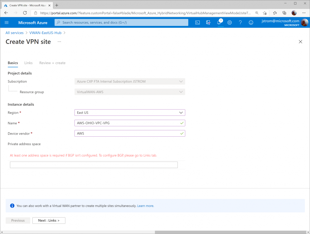
Specify a name for your VPN Site to define the connection connecting to AWS. Click Next : Links >

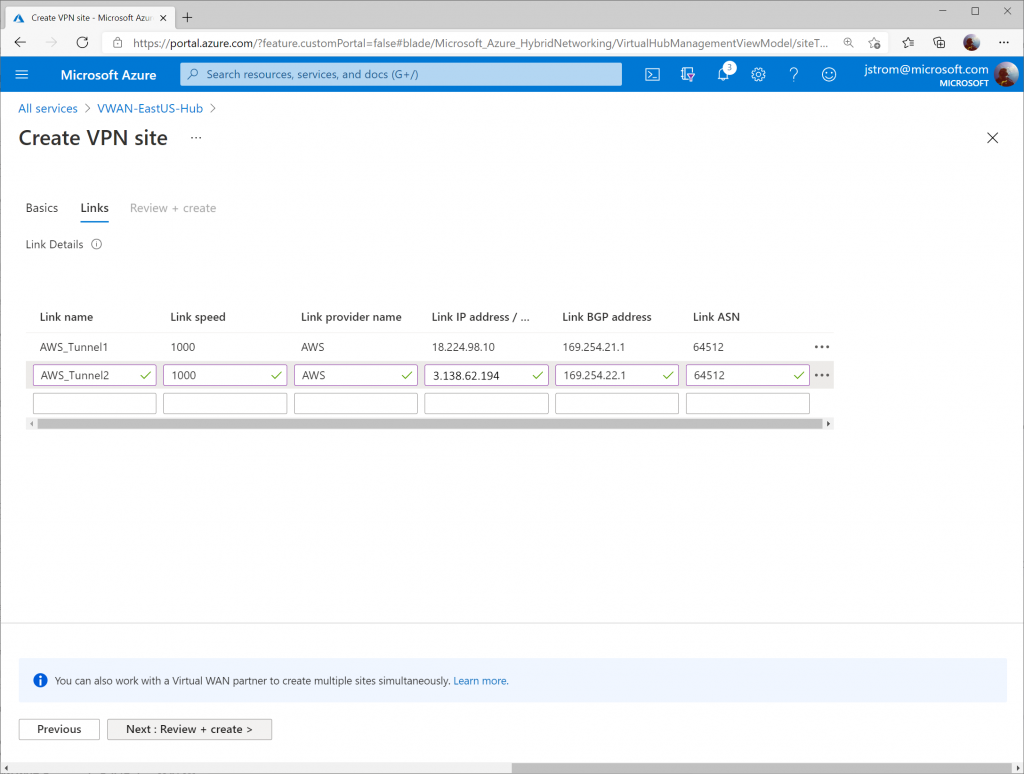
On the Links tab, add two entries with the following values (to tell VWAN how to connect to each of the AWS Site-to-Site connections). Note: this is very similar to AWS' Customer Gateway section.

Link 1:

  • Link Name; AWS_Tunnel1
  • Link Speed: 1000
  • Link Provider Name: AWS
  • Link IP address: 1.1.1.1 (this is a placeholder value until we configure the AWS side)
  • Link BGP address: 169.254.21.1
  • Link ASN: 64512

Link 2:

  • Link Name; AWS_Tunnel2
  • Link Speed: 1000
  • Link Provider Name: AWS
  • Link IP address: 1.1.1.2 (this is placeholder value until we configure the AWS side)
  • Link BGP address: 169.254.22.1
  • Link ASN: 64512

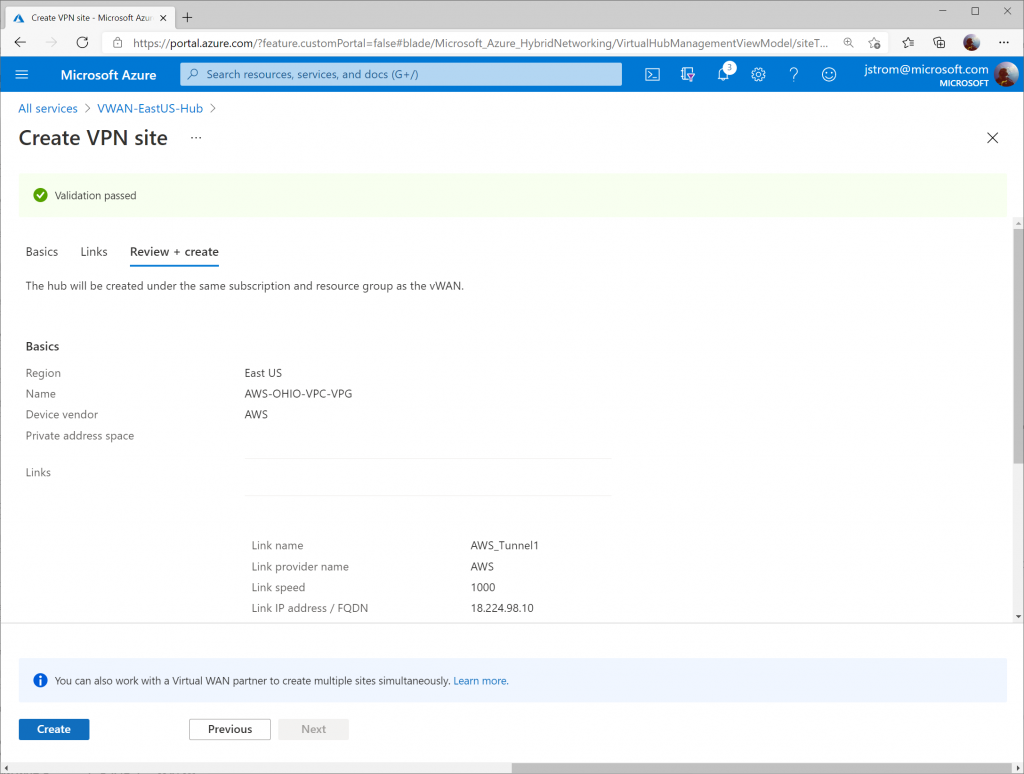
Click Next: Review + Create >

Click Create

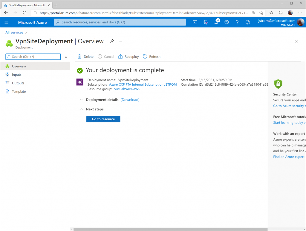
Click Go to resource once the links have finished being created.

Configure Phase 1/2 Proposals

Select your Virtual WAN hub on the Virtual WAN Overview blade.

Check the box for the new VPN Site Name and click the Connect VPN sites button

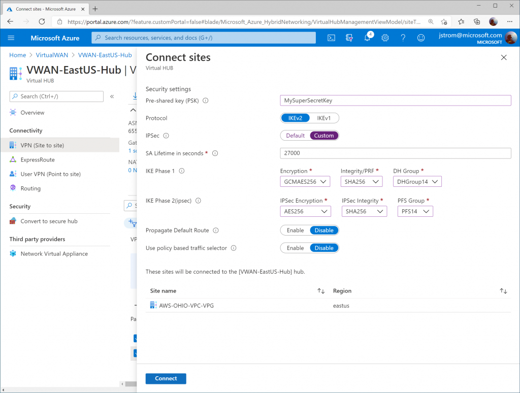
Specify the following configuration:

  • Pre-shared key (PSK): YourSecretKeyWithNumb3rs
    • Must be a 8-64 character string with alphanumeric, underscore(_), and dot(.). It cannot start with 0.
  • Protocol: IKEv2
  • IPSec: Custom
  • IKE Phase 1:
    • Encryption: GCMAES256
      • GCM algorithm is more efficient and can improve throughput on the Azure Gateways
    • Integrity/PRF: SHA256
    • DH Group: DHGroup14
  • IKE Phase 2 (ipsec):
    • IPSec Encryption: AES256
      • AWS does not support GCM algorithm for IPSec integrity at time of writing this, but if it is available, you may want to opt for that
    • IPSec Integrity: SHA256
    • PFS Group: PFS14

Click Connect

Configure AWS

Prerequisites

This guide assumes you have a VPC already (in my case, mine is called AWS-OHIO-VPC), a corresponding set of subnets for your servers, and a route table associated to your VPC.

Note: An AWS VPC is the equivalent of a VNet in Azure. One thing that is different between AWS and Azure is that in AWS you do not need to specify a subnet for your Gateways (i.e. "GatewaySubnet").

Create the Customer Gateways

Customer Gateways in AWS are the equivalent of a local network gateway that you'd associate to a connection for a traditional VPN Gateway in Azure. It is also the equivalent of a defined Site Link for Azure's Virtual WAN VPN configuration.

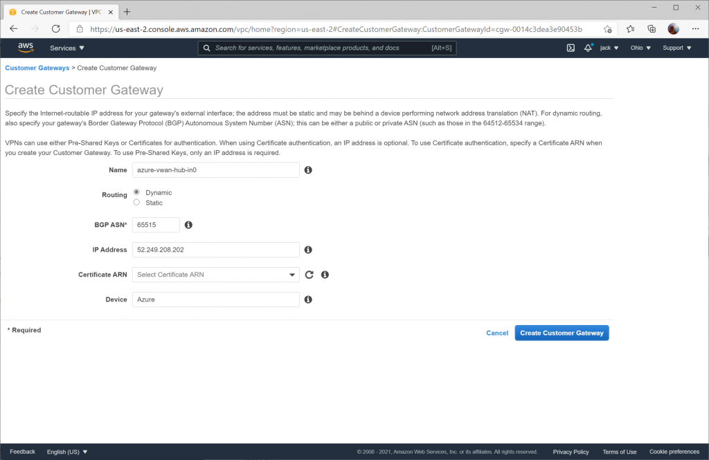
In this section, you will need to create two Customer Gateways. Specify the corresponding instance value obtained from the Configure Customer BPG IP address section. When creating the Customer Gateways ensure Dynamic routing is enabled and the BGP ASN is specified as 65515.

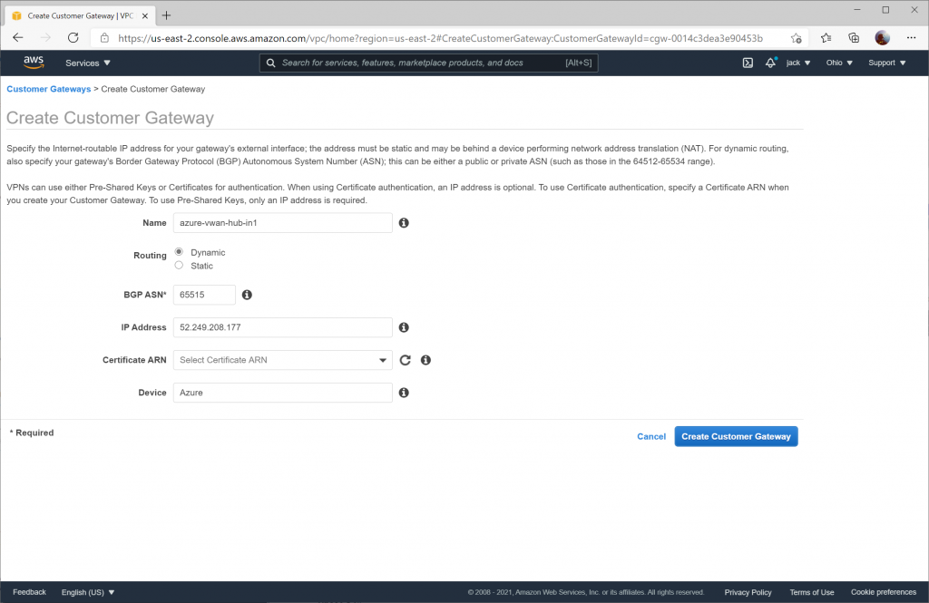
Configuration for the second Customer Gateway using the Instance 1 Gateway Public IP address.

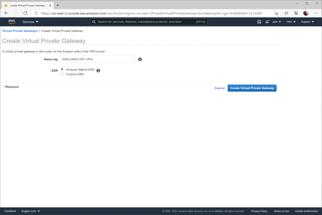
Create a Virtual Private Gateway

Next we need to create an AWS Virtual Private Gateway. This is the equivalent of Azure's VPN Gateway.

Create VPN Connections

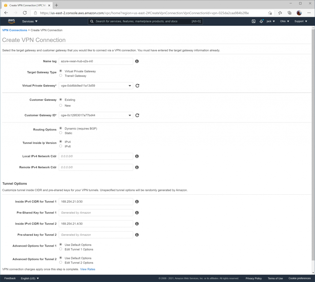
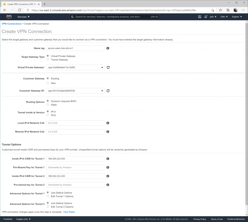
We need to create two VPN Connections, each VPN Connection linked to its corresponding Customer Gateway and VPC.

On the Inside IPv4 CIDR for Tunnel 1 on the first VPN Connection, ensure you use 169.254.21.0/30 as the BGP Peer addresses and 169.254.21.4/30 for the second tunnel. Due to the way that the VPN Connection works, we are using a placeholder value of 169.254.21.4/30 tunnel, which will never be used in practice since we cannot point it to leverage Azure's secondary VPN Gateway instance. This value must be specified as if we define the secondary BGP Peer address that will be created for the secondary instance in VWAN, you will receive an error that overlapping address space exists between this VPN Connection and the secondary VPN connection we create in AWS. Add the pre-shared key value you specified in Azure during this time as well.

When creating the second VPN connection, ensure 169.254.22.0/30 is specified for Inside IPv4 CIDR for Tunnel 1 and 169.254.22.4/30 is specified for Inside IPv4 CIDR for Tunnel 2 (which is again a placeholder value that won't be used).

Configure Route Table to Propagate Routes

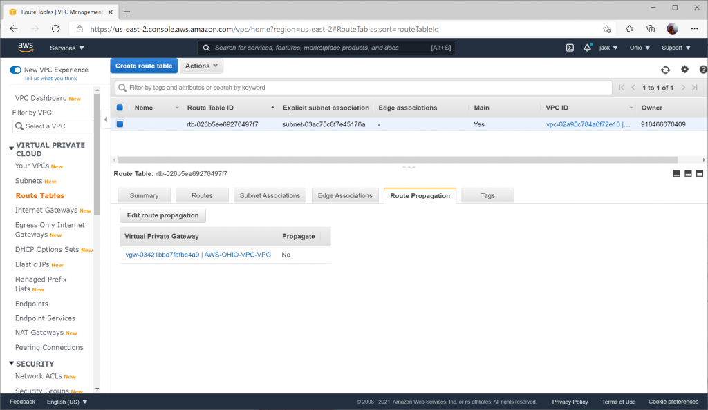
To allow the learned routes from BGP propagate to the VPC, you need to enable route propagation on your Route Table.

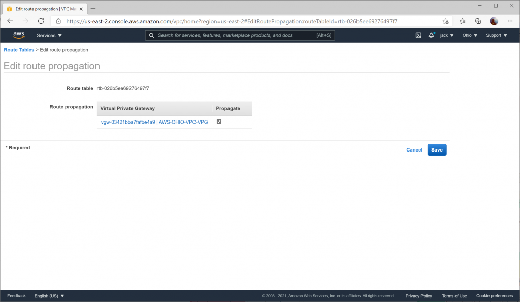
Navigate to Route Tables and select your Route Table and click the Route Propagation tab and select Edit route propagation

Check the Propagate box and click Save

Update Azure

Update Azure Site Link IP addresses

As per the Configure Phase 1/2 Proposals section for Azure Virtual WAN, you specified 1.1.1.1 and 1.1.1.2 as a placeholder value for the Public IP addresses of the AWS VPN Gateway instances. We will need to update these addresses with the proper values.

Naviate to your Virtual WAN instance and select your Virtual WAN hub

Select VPN (Site to site) and choose click on the Site name you created

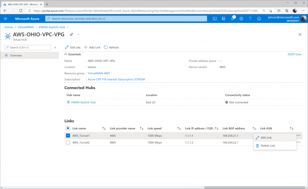
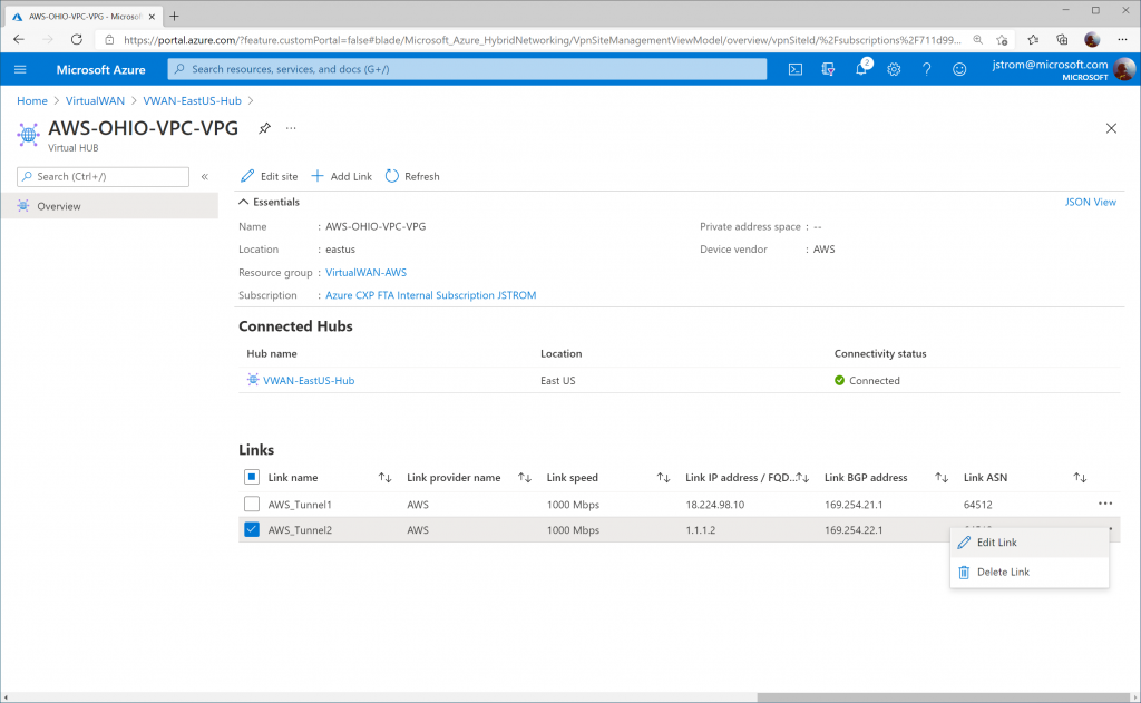
Click on the three dots (ellipsis) for AWS_Tunnel1 and click Edit Link.

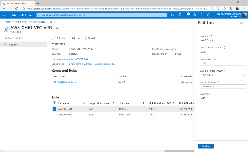
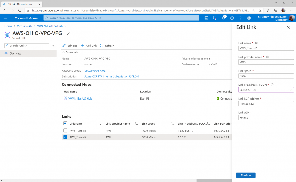
Specify the proper IP address for Tunnel 1 on AWS Site-to-Site connection 1. Click Confirm.

Click on the three dots (ellipsis) for AWS_Tunnel2 and click Edit Link.

Specify the proper IP address for Tunnel 1 on AWS Site-to-Site connection 2. Click Confirm.

Verify connectivity

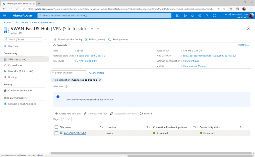
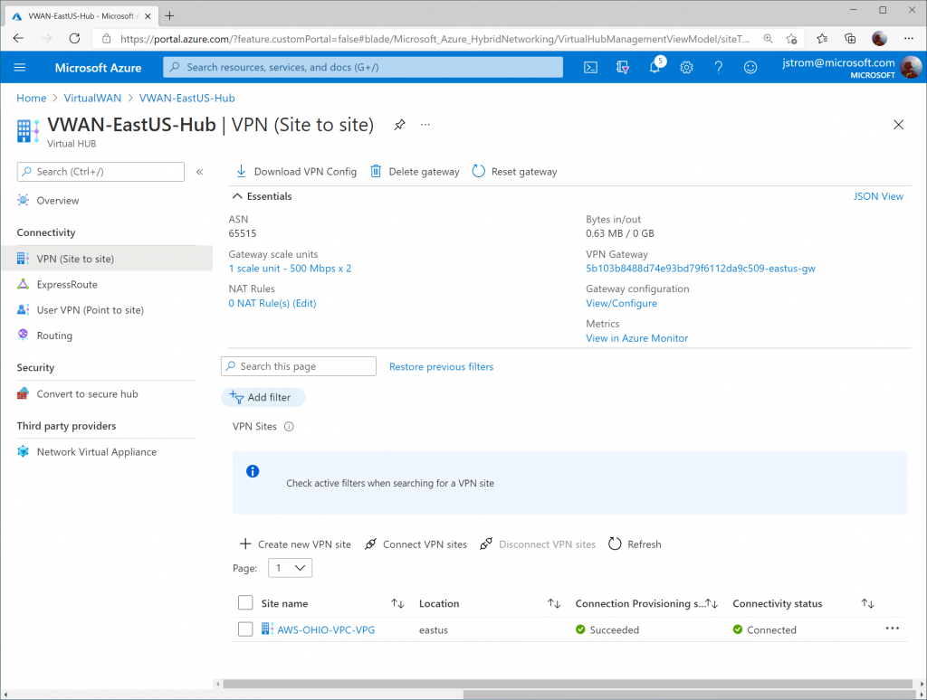
On the Azure Side, you should see the VPN Site's Connectivity status change to Connected

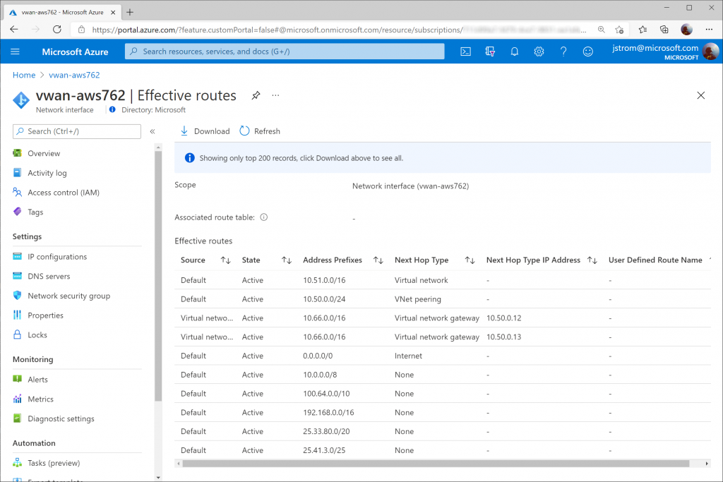
You can also select a Virtual Machine that may have it's virtual network attached to the VWAN Hub and validate you see learned routes from the VWAN Hub (and AWS) propagated into the VNet.

Tip: You can see the same route twice as we have both VPN Gateway instance BGP Peers actively connected to AWS. In the event you lose a peer, you would only see one route to one gateway listed.

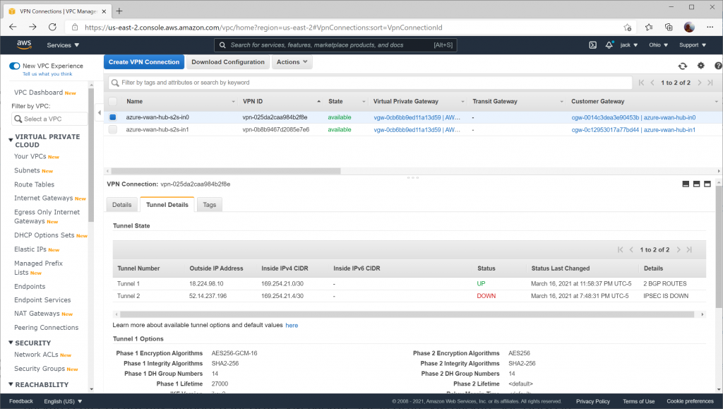
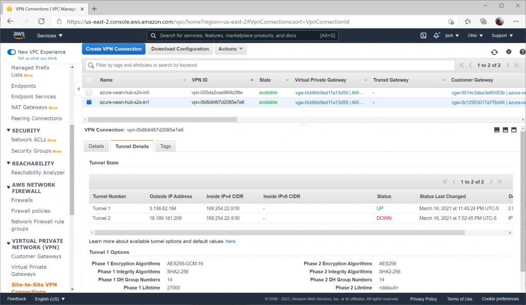
On the AWS side, you can validate for each Site to Site VPN connection that you see Tunnel 1's status as UP and Tunnel 2's status as DOWN (remember, Tunnel 2 will always be listed as down because a fictitious BGP is specified).

Here you can see the secondary Site-to-Site connection with the same status: UP for Tunnel 1, DOWN for Tunnel 2

Cheat sheet on Azure Subnetting

Here's a quick cheat sheet on recommended subnet sizing for Azure. Items in bold are subnet names reserved by the platform for their corresponding service.

GatewaySubnet - /27 - https://docs.microsoft.com/en-us/azure/vpn-gateway/vpn-gateway-about-vpn-gateway-settings#gwsub

Point-to-Site (P2S) addressing (VPN or VWAN) - Requires a non-vnet address space – depends on how many P2S clients - https://docs.microsoft.com/en-us/azure/vpn-gateway/point-to-site-about#gwsku

AzureBastionSubnet - /26 (as of Nov, 2021; previously was /27) - https://docs.microsoft.com/en-us/azure/bastion/bastion-create-host-portal#createhost

Azure Virtual WAN Hub - /24 - https://docs.microsoft.com/en-us/azure/virtual-wan/virtual-wan-site-to-site-portal#hub

AzureFirewallSubnet - /26 - https://docs.microsoft.com/en-us/azure/firewall/tutorial-firewall-deploy-portal#create-a-vnet

AzureFirewallManagementSubnet - /26 - Azure Firewall forced tunneling | Microsoft Docs

RouteServerSubnet - /27 - Quickstart: Create and configure Route Server using Azure PowerShell | Microsoft Docs

Application Gateway - min /27 per deployment - https://docs.microsoft.com/en-us/azure/application-gateway/configuration-overview#size-of-the-subnet

Azure AD Domain Services (AADDS) - min /28 - Network planning and connections for Azure AD Domain Services | Microsoft Docs

Azure SQL Managed Instance (SQL MI) - min /27 - https://docs.microsoft.com/en-us/azure/sql-database/sql-database-managed-instance-determine-size-vnet-subnet

App Services (Web Apps, Functions, API Apps) - min /27 - https://docs.microsoft.com/en-us/azure/app-service/web-sites-integrate-with-vnet

App Service Environment - /24 - https://docs.microsoft.com/en-us/azure/app-service/environment/network-info

Logic Apps integration service - /27 - https://docs.microsoft.com/en-us/azure/logic-apps/connect-virtual-network-vnet-isolated-environment#set-up-network-ports

API Management – min /29 - https://docs.microsoft.com/en-us/azure/api-management/api-management-using-with-vnet#--subnet-size-requirement

Azure Kubernetes Service (AKS) - depends on node count -  https://docs.microsoft.com/en-us/azure/aks/configure-azure-cni#plan-ip-addressing-for-your-cluster

Azure Container Instances (ACI) - /29 - https://docs.microsoft.com/en-us/azure/container-instances/container-instances-vnet

Azure Databricks - Requires 2 subnets (Public/Private) – min of two /26 - https://docs.azuredatabricks.net/administration-guide/cloud-configurations/azure/vnet-inject.html#virtual-network-requirements

Azure NetApp Files - /28 - https://docs.microsoft.com/en-us/azure/azure-netapp-files/azure-netapp-files-delegate-subnet

Azure Dedicated HSM - /28 - https://docs.microsoft.com/en-us/azure/dedicated-hsm/networking#subnets

Azure VMware Solutions - /22 - https://docs.microsoft.com/en-us/azure/azure-vmware/tutorial-network-checklist#routing-and-subnet-considerations

Azure Spring Cloud - /28 - Deploy Azure Spring Cloud in a virtual network | Microsoft Docs

Notes

Microsoft has added a list of services that can be injected into Virtual Networks as well here: https://docs.microsoft.com/en-us/azure/virtual-network/virtual-network-for-azure-services#services-that-can-be-deployed-into-a-virtual-network

Deploying FortiGate Virtual Appliances (FortiGate-VM) on Azure

Here is a recap of some of the reflections I have with deploying Fortinet's FortiGate appliance on Azure. This is more of a reflection of the steps I took rather than a guide, but you can use the information below as you see fit.  At a high level, you will need to deploy the device on Azure and then configure the internal “guts” of the device to allow it to route traffic properly on your Virtual Network (VNet) in Azure. While Fortinet does have some documentation on deploying their appliance, I found it very confusing, so I hope this helps walk through deployment. At the time of writing this, v6.2 was the latest version; however I recommend using at least version 6.0 or greater as it provides support for auto-scaling, which is what we will be looking at for this guide.

First, just want to provide a quick overview of the different options you can take and a rough overview of each architecture:

Deploy the Appliance in Azure

As part of this tutorial, we will look at FortiGate's Autoscaling deployment as this will allow us to dynamically scale up or down depending on load. In addition, this deployment will provide us high availability, so in the event we lose a VM, network traffic will automatically failover to another appliance.

Architecture

A high level overview of what resources are deployed

Deployment

  1. Login to the Azure Portal
    1. https://portal.azure.com
  2. Create two new Resource Groups
    1. Navigate to All services -> Resource Groups
    2. Click Add 
    3. Create two new resource groups with the following names (they can be different if you wish, but you will need at least 2)
      1. Fortigate-Handler-RG
      2. Fortigate-VMSS-RG
  3. Create a Service Principal
    1. Navigate to All services -> Azure Active Directory
    2. Select App registrations
    3. Click New Registration
      1. Name: Fortigate-NVA
      2. Supported account types: Accounts in this organizational directory only
      3. Redirect URI: leave blank
    4. Click Register
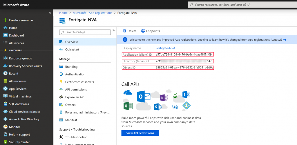
    5. Write down the Application (client) ID, Directory (tenant) ID, and Object ID.
    6. Click on Certificates & secrets
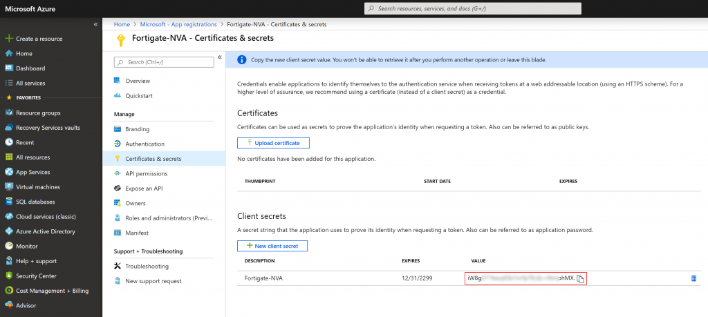
    7. Click on the New client secret button and set the description to Fortigate-NVA, set the password expiry to your preference and click Add
    8. Write down the value of your client secret
      1. Note: once you navigate away from the blade you won't be able to retrieve it again
  4. Delegate the Service Principal
    1. Navigate to All services -> Subscriptions -> select your subscription -> and select Access control (IAM)
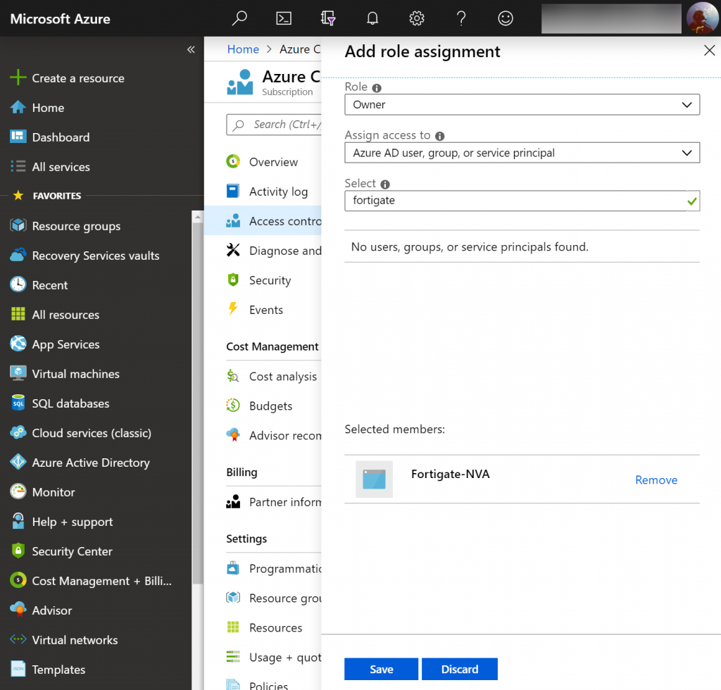
    2. Click Add, Add role assignment, and use the following configuration
      1. Role: Owner
      2. Assign access to: Azure AD user, group, or service principal
      3. Select: Search for Fortigate-NVA and select it
    3. Click Save

      1. Note: I didn't have a chance to test, but I think these permissions could likely be delegated down at the resource group level vs subscription.  If someone could confirm, please leave a comment below.
  5. Deploy the Fortigate Handler (CosmosDB and Function App)
    1. Once you click the button above to deploy the template, use the following configuration
      1. Function App Name
        1. This is the name of the Azure Function resource that gets created.  This must be globally unique across all customers within Azure.
      2. Cosmos DB Name
        1. Name of the Cosmos DB that will be created. This field must be between 3 and 31 characters and can contain only lowercase letters, numbers and -.  This value should be globally unique across all customers within Azure.
      3. Storage Account Type: Standard_LRS
      4. Tenant ID
        1. Use the Directory (tenant) ID from the Service Principal we created earlier.
      5. Subscription ID
        1. Enter the subscription ID to the Azure Subscription you wish to deploy to.  You can find your subscription ID by navigating to All services -> Subscriptions and selecting your subscription.
      6. Rest App ID
        1. Use the Application (client) ID from the Service Principal we created earlier.
      7. Rest App Secret: iW8gS...........................pMX
        1. Use the value you wrote down when generating the Client Secret when creating the Service Principal.
      8. Heart Beat Loss Count: 3
        1. Number of consecutively lost heartbeats. When the heartbeat loss count has been reached, the VM is deemed unhealthy and failover activities commence.
      9. Scaling Group Resource Group Name: Fortigate-VMSS-RG
        1. This is the value of the secret Resource Group you created at the beginning of this guide.  This Resource Group will contain the VM Scale Set and it's corresponding resources.
      10. Script Timeout: 230
        1. This is the timeout for the Function App script to run.  By default this is 230 seconds.
      11. Election Wait Time: 90
        1. This is the maximum time (in seconds) to wait for a master election for the FortiGate's to complete.
      12. PSK Secret: mysupersecretpassphrase
        1. This is a random string of characters used by the FortiGates in the scale set to synchronize configuration items.
      13. Package Res URL: https://github.com/fortinet/fortigate-autoscale/releases/download/1.0.3/fortigate-autoscale-azure-funcapp.zip
        1. Grab the latest version of the package for the Azure Function App from GitHub.  You can find the latest compiled versions here: https://github.com/fortinet/fortigate-autoscale/releases
  6. Deploy the VM Scale Set
    1. Once you click the button above to deploy the template, use the following configuration
      1. Instance Type: Standard_F2
      2. FOS Version: 6.2.1
      3. VNet New Or Existing: new
        1. Select whether you wish to use an existing or new Virtual Network
      4. VNet Name: AzureHubVNet
        1. The name of the VNet to be used or created.
      5. Subnet Address Prefix: 10.0.0.0/16
        1. The address space of the VNet to be used or created.
      6. Subnet1Name: Untrust
        1. The name of the subnet that will be public facing to the internet.
      7. Subnet1Prefix: 10.0.1.0/24
        1. The address space of the subnet to be created for the public facing zone.
      8. Subnet2Name: Trust
        1. The name of the subnet that will contain the private NICs of the FortiGate's.
      9. Subnet2Prefix: 10.0.2.0/24
        1. The address space of the subnet to be created for the private facing zone.
      10. Subnet2Load Balancer IP: 10.0.2.10
        1. The IP address of the load balancer in the private zone.
      11. Subnet3Name: Private
        1. The name of the subnet that will contain the private machines that are behind the FortiGate appliance.
      12. Subnet3Prefix: 10.0.3.0/24
        1. The address space of the subnet that will contain the private machines that are behind the FortiGate.  Note: this is more of a place holder in FortiGate's template, you can create additional subnets later on/use a different subnet for your private resources.
      13. Public IP New or Existing: new
        1. The Public IP address to be associated as the VIP of the Azure Load Balancer for incoming traffic.
      14. Scaling Group Name Prefix: fgtasg
        1. The prefix each VMSS Name is given when deploying the FortiGate autoscale template. The value of this parameter should be the same as for deploy_funcapp.json. The prefix cannot contain special characters \/""[]:|<>+=;,?*@& or begin with '_' or end with '.' or '-'.
      15. Initial Capacity: 2
        1. How many FortiGate's should be deployed.  Default value is 1, however I recommend at least 2 for high availability.
      16. Min Capacity: 2
        1. The smallest amount of FortiGate's that should be running.  Default value is 1, however I recommend at least 2 for high availability.
      17. Max Capacity: 3
        1. The max amount of FortiGate's that should be deployed.
      18. Scale Out Threshold: 80
        1. Percentage of CPU utilization at which scale-out should occur.
      19. Scale In Threshold: 20
        1. Percentage of CPU utilization at which scale-in should occur.
      20. Admin Username: azureadmin
        1. FortiGate administrator username on all VMs.
      21. Admin Password: azurepassword
        1. FortiGate administrator password on all VMs. This field must be between 11 and 26 characters and must include at least one uppercase letter, one lowercase letter, one digit, and one special character such as (! @ # $ %).
      22. Endpoint URL: https://yourfunctionappurl.azurewebsites.net
        1. This can be found by navigating to All services -> Function App -> YourFunctionApp -> URL on the overview blade.

At this point, your FortiGate deployment should be completed. When a FortiGate appliance comes up, it will reach out to the Azure Function to pull down its base configuration. Any changes to the primary FortiGate will be synchronized to any additional FortiGates deployed as well.

For those using a hub/spoke network, you will want to associate a UDR to each of your subnets to force traffic back to the internal load balancer's VIP. You can do this by creating a new Route Table, add a Route, set the next hop type to Virtual Appliance, and set the IP address to the IP address you specified for the "Subnet2Load Balancer IP".

You can connect to the primary FortiGate for management via web console on Port 8443 (https://IP.AD.DR.ESS:8443) or via SSH on Port 22.

References

https://docs.fortinet.com/vm/azure/fortigate/6.2/azure-cookbook/6.2.0/128029/about-fortigate-vm-for-azure

Deploying Cisco Virtual Appliances (NGFWv) on Azure

Here is a recap of some of the reflections I have with deploying Cisco NGFWv (Next Generation Firewall Virtual) on Azure. This is more of a reflection of the steps I took rather than a guide, but you can use the information below as you see fit.  At a high level, you will need to deploy the device on Azure and then configure the internal "guts" of the Cisco device to allow it to route traffic properly on your Virtual Network (VNet) in Azure. While Cisco does have decent documentation on deploying a single appliance, the primary purpose of this document is to look at HA/Scale out deployments.

First, just want to provide a quick overview of some of Cisco's offerings today for Azure:

  • Cisco CSR
  • Cisco Meraki
    • In Cisco’s words:
      • Virtual MX is a virtual instance of a Meraki security & SD-WAN appliance, dedicated specifically to providing the simple configuration benefits of site-to-site Auto VPN for customers running or migrating IT services to an Amazon Web Services or Microsoft Azure Virtual Private Cloud (VPC).
    • Source: https://meraki.cisco.com/products/appliances/vmx100
  • Cisco ASAv
    • In Cisco's words:
      • The ASAv is a virtualized network security solution that provides policy enforcement and threat inspection across heterogeneous, multisite environments.
      • ASA firewall and VPN capabilities help safeguard traffic and multitenant architectures. Available in most hypervisor environments, the Cisco ASAv can be deployed exactly where it is needed to protect users and workloads on-premises or in the cloud.
    • Source: https://github.com/cisco/asav
  • Cisco Firepower NGFW (Threat Defense Virtual)
    • In Cisco's words:
      • The Cisco Firepower® NGFW (next-generation firewall) is the industry’s first fully integrated, threat-focused next-gen firewall with unified management. It uniquely provides advanced threat protection before, during, and after attacks.
      • The Firepower Threat Defense Virtual (FTDv) is the virtualized component of the Cisco NGFW solution. Organizations employing SDN can rapidly provision and orchestrate flexible network protection with Firepower NGFWv. As well, organizations using NFV can further lower costs utilizing Firepower FTDv.
    • Source: https://github.com/cisco/firepower-ngfw

Deploy the Appliance in Azure

In deploying the Cisco appliances, you'll notice you can deploy from the Azure Marketplace: https://azuremarketplace.microsoft.com/en-us/marketplace/apps/cisco.cisco-firepower-threat-defense-appliance?tab=Overview).  Personally, I'm not a big fan of deploying the appliance this way as I don't have as much control over naming conventions, don't have the ability to deploy more than one appliance for scale, cannot specify my availability set, etc. While Cisco does offer an ARM template, it doesn't allow flexibility for more than two devices, nor configures anything from a load balancer perspective. In this case, I've written a custom ARM template that leverages managed disks, availability sets, consistent naming nomenclature, proper VM sizing, and most importantly, let you define how many virtual instances you'd like to deploy for scaling.

Note: this article doesn't cover deployment of Cisco's Firepower Management Center, which is what is used to centrally manage each of the scale-out instances in a "single pane of glass".

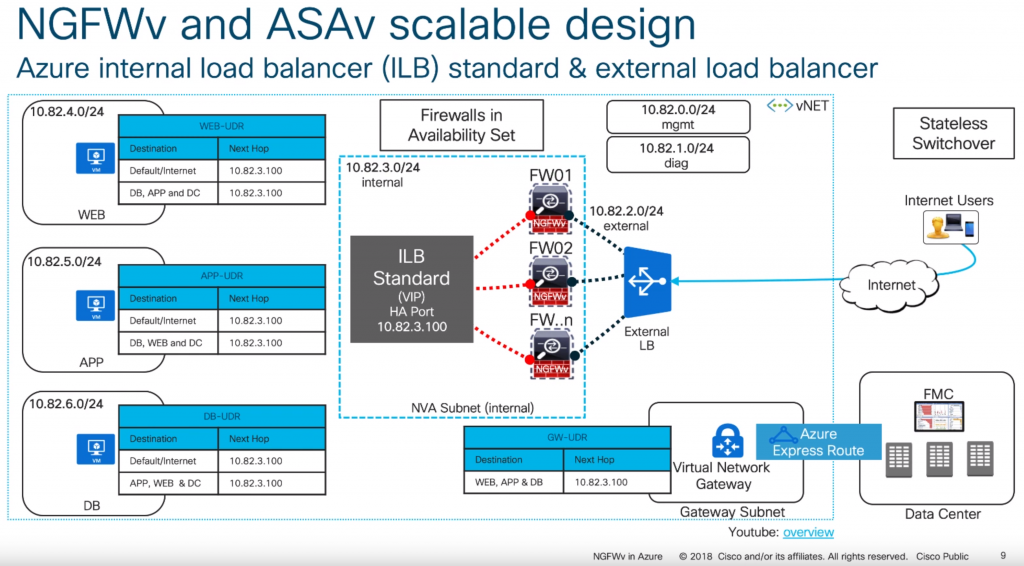
With the above said, this article will cover what Cisco calls their "scalable design" model. Here is an example of what this visually looks like (taken from one of their slide decks listed in the notes section at the bottom of this article):

Scalable design model as per Cisco's Reference Architecture

Below is a link to the ARM template I use.

Cisco-NGFWv-HA.json

Deployment of this template can be done by navigating to the Azure Portal (portal.azure.com), select Create a resource, type Template Deployment in the Azure Marketplace, click Create,  select Build your own template in the editor, and paste the code into the editor.

Alternatively, you can click this button here:

Here are some notes on what the parameters mean in the template:

VMsize: Per Cisco, the recommend VM sizes should be D3v2, D4v2, or D5v2.  Interestingly, they don't call out the use of Premium storage anywhere, which I would highly recommend using if this was a single instance machine (to get at least some sort of SLA by Azure).

CiscoSku: Here is where you can select to use bring-your-own-license or pay-as-you-go.  Plans are should be outlined in the following link, but oddly enough the BYOL image is only available via PowerShell and their plans don't show it:  https://azuremarketplace.microsoft.com/en-us/marketplace/apps/cisco.cisco-firepower-threat-defense-appliance?tab=PlansAndPrice

CiscoVersion: The version of the Cisco appliance to deploy.

CiscoCount: This defines how many virtual instances you want deployed and placed behind load balancers.

VNetName: The name of your virtual network you have created.

VNetRG: The name of the resource group your virtual network is in.  This may be the same as the Resource Group you are placing the Cisco devices in, but this is a needed configurable option to prevent errors referencing a VNet in a different resource group.

envPrefix: All of the resources that get created (load balancer, virtual machines, public IPs, NICs, etc.) will use this naming nomenclature.

manPrivateIPPrefix, diagPrivateIPPrefix, trustPrivateIPPrefix, untrustPrivateIPPrefix: Corresponding subnet address range.  These should be the first 3 octets of the range followed by a period.  For example, 10.5.6. would be a valid value.

manPrivateIPFirst, diagPrivateIPFirst, trustPrivateIPFirst, untrustPrivateIPFirst: The first usable IP address on the subnet specified.  For example, if my subnet is 10.4.255.0/24, I would need to specify 4 as my first usable address.

Username: this is the name of the privileged account that should be used to ssh and login to the PanOS web portal.

NewStorageAccountName: this is the name of the storage account that will store boot diagnostics for the Cisco appliances. This will give you the ability to see what the serial console shows. This value should be alphanumeric and 3-24 characters.

Password: Password to the privileged account used to ssh and login to the device.

Configure the Appliance

Complete these steps for both devices.

  1. SSH to the device via it's public or private IP address of the management interface
    1. Please note, SSH may not come up for another 10+ minutes after deployment has finished, even though the VMs show running. There are several tasks within the Cisco appliance that run post-provisioning which take awhile to complete before the ability to SSH works.
  2. Login using the following credentials
    1. Note: Even though we specified credentials within our template, cisco has a default set of admin credentials "baked" into the image and they should be specified during first login (which prompts you to immediately change). Please login using the default admin credentials.
    2. Username: admin
    3. Password: Admin123
      1. The password is case sensitive, you should use a capital A on Admin123.
  3. Change your password once prompted
  4. Enter y to configure IPv4
  5. Enter n to not configure IPv6
    1. As of 6/1/2019, Azure only has preview support for IPv6, so this article won't cover any IPv6 specific items
  6. Enter dhcp to configure IPv4 with DHCP
    1. All addresses in Azure should be DHCP, static addresses are set within Azure, which essentially give the appliance a DHCP reservation
    2. Important Note: Once you configure this option, you'll get an awkward "If your networking information has changed, you will need to reconnect" message and things will appears to be stuck. Be patient, it appears a script runs in the background, you'll see it eventually prompt for the next question.
  7. Leave your SSH connection open for the next step

Configure NGFWv to use FirePower Management Center

Once you have gone through the initial configuration on both devices, you will need to register the sensor to a Firepower Management Center instance. To do this, you will need to run the configure manager command on both appliances. Please note I've listed the command below with the parameters it will accept, you will need to use the applicable values for your environment.

configure manager add {hostname | IPv4_address | IPv6_address | DONTRESOLVE} reg_key [nat_id]

Per Cisco's documentation:

  • The registration key is a user-defined one-time use key that must not exceed 37 characters. Valid characters include alphanumeric characters (A–Z, a–z, 0–9) and the hyphen (-). You will need to remember this registration key when you add the device to the Firepower Management Center.
  • If the Firepower Management Center is not directly addressable, use DONTRESOLVE.
  • The NAT ID is an optional user-defined alphanumeric string that follows the same conventions as the registration key described above. It is required if the hostname is set to DONTRESOLVE. You will need to
    remember this NAT ID when you add the device to the Firepower Management Center

Add the appliances into FirePower Management Center

Repeat the following steps for each of the appliances you deployed

  1. Login to FirePower Management Center
  2. Select the Devices tab, click Device Management, and then click the Add button
  3. Enter the following
    1. Host: ManagementIP
    2. Device Name: FriendlyDeviceNameOrHostName
    3. Registration Key: KeyYouUsedWhenRunningConfigureManagerCommandAbove
    4. Access Control Panel
      1. Specify a Name, select Network Discovery
    5. Smart Licensing
      1. Check the following you are licensed for
        1. Malware
        2. Threat
        3. URL Filtering
    6. If you used NAT, configure NAT and specify the NAT ID
    7. Click Register

Initialize the interfaces on your appliances

Repeat the following steps for each of the appliances you deployed

  1. Select the Devices tab, click Device Management, and select the edit button (Pencil Icon) for your appliance
  2. Click the edit button (Pencil Icon) for GigabitEthernet 0/0
    1. Name: Untrust
    2. Check the Enabled checkbox
    3. Security Zone: Create a new zone called Untrusted
    4. Click the IPv4 tab
      1. IP Type: Use Static
      2. IP Address: IPAddressOfYourAppliance/SubnetSize
    1. Click OK
  3. Click the edit button (Pencil Icon) for GigabitEthernet 0/1
    1. Name: Trust
    2. Check the Enabled checkbox
    3. Security Zone: Create a new zone called Trusted
    4. Click the IPv4 tab
      1. P Type: Use Static
      2. IP Address: IPAddressOfYourAppliance/SubnetSize
    5. Click OK
  4. Click the Save button

Once you have completed the steps above, click Deploy, select each of your appliances, and click Deploy to push the configuration to the device

Configure static routes on your device

In this section, we will create several routes to handle the flow of traffic to and to/from your trusted subnets, traffic destined towards the internal, traffic destined towards the management interface (we'll need this to help handle the health probes from the azure load balancer later on), and a specific route to define the Azure Health Probes themselves.

Repeat the following steps for each of the appliances you deployed.

  1. Select the Devices tab, click Device Management, and select the edit button (Pencil Icon) for your appliance
  2. Select the Routing tab and click Static Route
  3. Click the Add Route button
    1. Type: IPv4
    2. Interface: Trust
    3. Create new network objects
      1. Add network objects that represent each of the subnets you have in Azure that the device will need to return traffic to
        1. For example, you'd repeat these steps for each private subnet
          1. Name: DBServers
          2. Network: 10.3.5.0/24
          3. Click Save
      2. Add network object for the appliance's management interface
        1. Name: YourAppliance-mgmt
        2. Network: IPAddressOfManagementInterface
          1. Use the private IP of your management interface
        3. Click Save
      3. Add network object for Azure Health Probes
        1. Name: Azure-LB-Probe
        2. Network: 168.63.129.16
        3. Click Save
    4. Add the defined network objects above to Selected Network box
    5. Gateway: Use the IP address of the default gateway of your subnet the Trust interface is deployed on
      1. Note: To find this, navigate to the Azure Portal (portal.azure.com) and select All Services -> Virtual Networks -> Your Virtual Network -> Subnets and use the first IP address of your subnet the trusted interface is on.  For example, if the address range of my subnet is 10.5.15.0/24, I would use 10.5.15.1 as my IP address.  If my subnet was 10.5.15.128/25, I would use 129 10.5.15.129 as my IP address
    6. Metric: 3
    7. Click OK
  4. Click the Add Route button
    1. Type: IPv4
    2. Interface: Untrust
    3. Add the any-ipv4 object to Selected Network box
      1. This will allow us to force all internet bound traffic through our Untrust interface
    4. Add the Azure-LB-Probe object to the Selected Network box
      1. This will allow health probes from the external azure load balancer probes to flow properly
    5. Add the YourAppliance-mgmt object to the Selected Network box
    6. Gateway: Use the IP address of the default gateway of your subnet the Untrust interface is deployed on
      1. Note: To find this, navigate to the Azure Portal (portal.azure.com) and select All Services -> Virtual Networks -> Your Virtual Network -> Subnets and use the first IP address of your subnet the untrusted interface is on.  For example, is the address range of my subnet is 10.5.15.0/24, I would use 10.5.15.1 as my IP address.  If my subnet was 10.5.15.128/25, I would use 129 10.5.15.129 as my IP address
    7. Metric: 2
    8. Click OK
  5. Click the Save button

Once you have completed the steps above, click Deploy, select each of your appliances, and click Deploy to push the configuration to the device

Configure NAT Policies

First create a NAT rule that will SNAT any traffic from our trusted zone to the Untrust interface. This is needed so Azure understands to return traffic through the external interface of your device for inspection.

  1. Select the Devices tab, click NAT, and select the Threat Defense NAT Policy link (or New Policy button)
  2. Select your first appliance, click the Add to Policy button, and click Save
  3. Click the Add Rule button
    1. NAT Rule: Auto NAT Rule
    2. Type: Dynamic
    3. Interface Objects Tab
      1. Select the Trusted Interface Object and click the Add to Source button
      2. Select the Untrusted Interface object and click the Add to Destination button
    4. Translation Tab
      1. Click the green button to add a new network object under Original Packet
        1. Name: any-ipv4
        2. Network: 0.0.0.0/0
        3. Click Save
      2. Original Source: any-ipv4
      3. Translated Source: Destination Interface IP
    5. Click OK

Next, we need to create a new NAT statement to handle traffic for our load balancer probes. We will need to configure two statements since we will receive health probes from the same IP address (168.63.129.16) to both NICs. On the same appliance, continue the following steps.

  1. Click the Add Rule button
    1. NAT Rule: Manual NAT Rule
    2. Type: Static
    3. Interface Objects Tab
      1. Select the Trusted Interface Object and click the Add to Source button
      2. Select the Untrusted Interface object and click the Add to Destination button
    4. Translation Tab
      1. Original Source: Azure-LB-Probe
      2. Original Destination: Source Interface IP
      3. Original Destination Port: SSH
      4. Translated Source: Destination Interface IP
      5. Translated Destination: YourAppliance-mgmt
      6. Translated Destination Port: SSH
    5. Click OK
  2. Click the Add Rule button
    1. NAT Rule: Manual NAT Rule
    2. Type: Static
    3. Interface Objects Tab
      1. Select the Untrusted Interface Object and click the Add to Source button
      2. Select the Trusted Interface object and click the Add to Destination button
    1. Translation Tab
      1. Original Source: Azure-LB-Probe
      2. Original Destination: Source Interface IP
      3. Original Destination Port: SSH
      4. Translated Source: Destination Interface IP
      5. Translated Destination: YourAppliance-mgmt
      6. Translated Destination Port: SSH
  3. Click OK

Optional Step: If you are using the appliances to front applications to the internet, you will also need to configure a NAT rule for ingress traffic. This is an optional step, but will show you how to configure traffic to let's say a web server (which the ALB is configured to listen for per the template). If you do complete this step, make sure you add an access policy (Policies -> Access Control -> Select your policy -> click Add Rule).

  1. Click the Add Rule button
    1. NAT Rule: Manual NAT Rule
    2. Type: Static
    3. Interface Objects Tab
      1. Select the Untrusted Interface Object and click the Add to Source button
      2. Select the Trusted Interface object and click the Add to Destination button
    4. Translation Tab
      1. Original Source: any-ipv4
      2. Original Destination: Source Interface IP
      3. Original Destination Port: HTTP
      4. Translated Source: Destination Interface IP
      5. Translated Destination: webserver
        1. Click the green add button to create a new network object to define the private IP address of your web server.
      6. Translated Destination Port: HTTP
    1. Click OK

Click Save once you have finished adding the rules.

At this point, you will need to repeat the same steps above. The reason why we cannot apply the policy to both devices is when you configure the rule for the Azure Health Probes, you'll need to specify the correct Translated Destination (I.e. Appliance1 should use the network object that resolves to appliance 1; Appliance2 should use the network object that resolves to appliance 2)

Once you have completed the steps above, click Deploy, select each of your appliances, and click Deploy to push the configuration to the device

Finalize the environment

Now that the environment is configured, there are two steps you will want to check back on.

  1. Add Route Tables to each subnet to force traffic to the Cisco appliances
    1. You will need to leverage route tables with custom routes to force traffic to the Cisco appliance. I'd highly recommend giving this a read to familiarize yourself with how Route Tables work in Azure: https://docs.microsoft.com/en-us/azure/virtual-network/virtual-networks-udr-overview
  2. Ensure there is a Network Security Group (NSG) on the Untrust subnet
    1. As per Azure Load Balancer's documentation, you will need an NSG associated to the NICs or subnet to allow traffic in from the internet. https://docs.microsoft.com/en-us/azure/load-balancer/load-balancer-standard-overview#securebydefault
  3. Remove the public IP from your management interface
    1. Considering at this point you've configured the device and have private connectivity via VPN or ExpressRoute, I'd remove the public IP from your management interface to prevent the public internet from accessing this interface
  4. Adjust NSG rules
    1. Similar to above, I'd scope down who/what network segments can pass traffic to the device. Go back and modify the NSG on the management interfaces to only allow traffic from specific source addresses.

References

[How-To] Upgrade the firmware on a Dell PowerConnect N2000/3000 series switch

  1. Download the latest firmware from Dell's website
    1. Navigate to http://www.dell.com/support/ and enter in your service tag.  You should see downloads for this product, grab the latest firmware that is in a zipped folder.
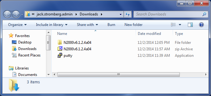
  2. Extract the .zip folder of the firmware
    N2000 Firmware
  3. Console into the switch via SSH or direct console
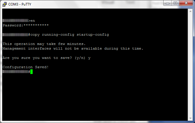
  4. Copy the current configuration to startup
    1. console#> copy running-config startup-config
      N2000-3000 - copy running-config startup-config
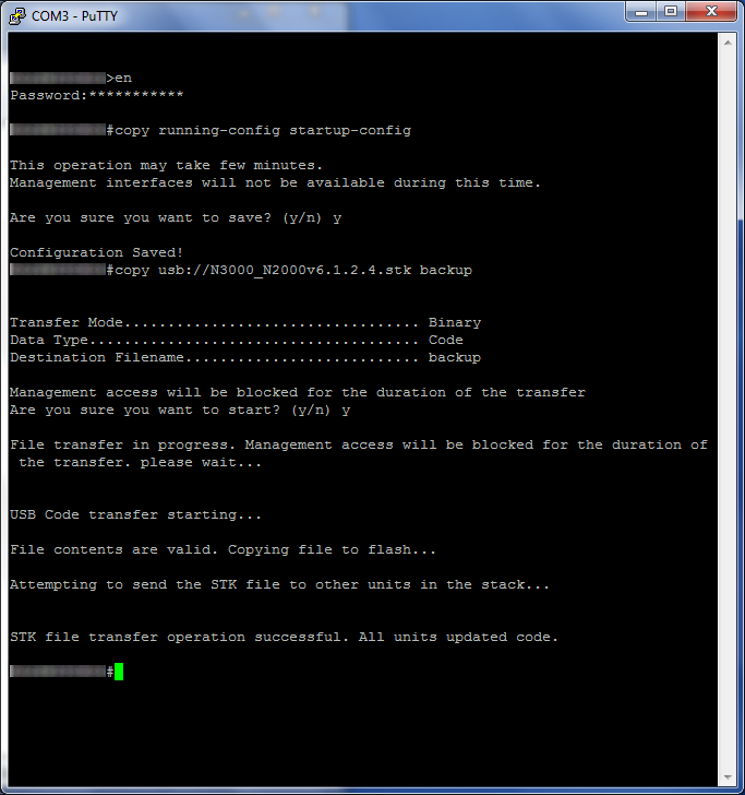
  5. Transfer the firmware to the switch
    1. TFTP Method
      1. console#> tftp://N3000_2000v6.1.2.4.stk backup
    2. USB Method (Directly attached to switch)
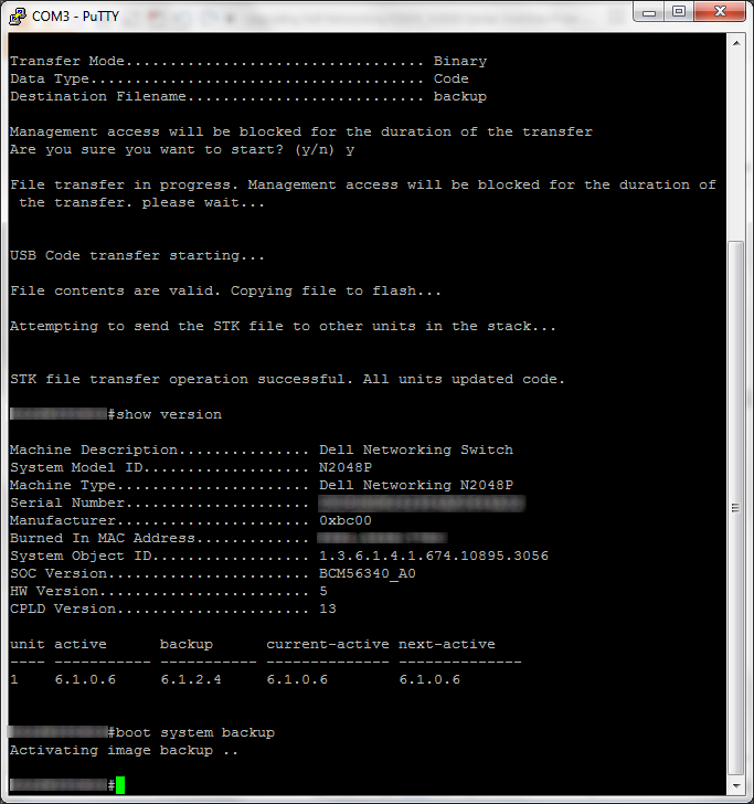
      1. console#> usb://N3000_2000v6.1.2.4.stk backup
        N2000-3000 - usb transfer - backup
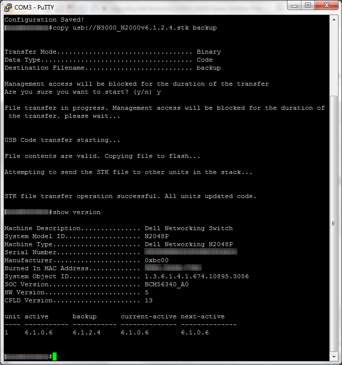
  6. Verify the backup version is the new build
    1. console#> show version
      N2000-3000 - backup - version
  7. Activate the new firmware
    1. console#> boot system backup
      N2000-3000 - backup - boot system backup
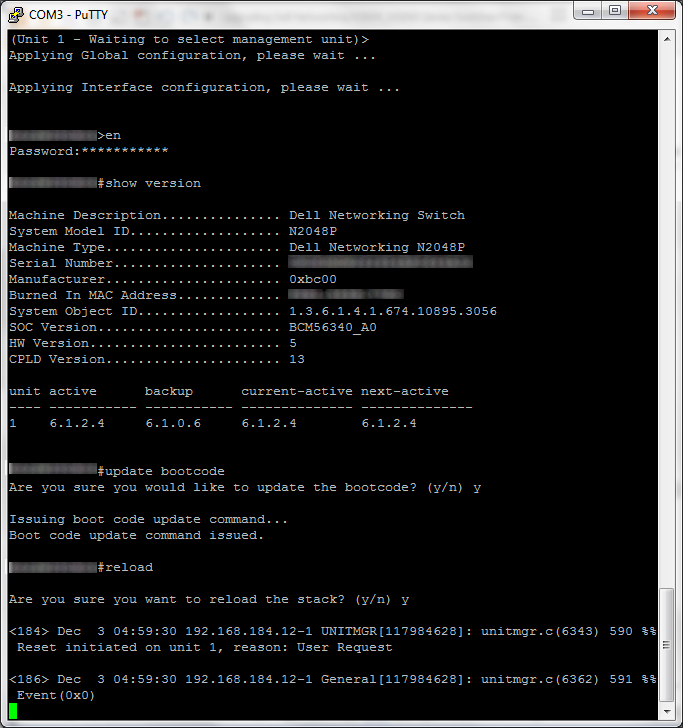
  8. Reboot the switch
    1. console#> reload
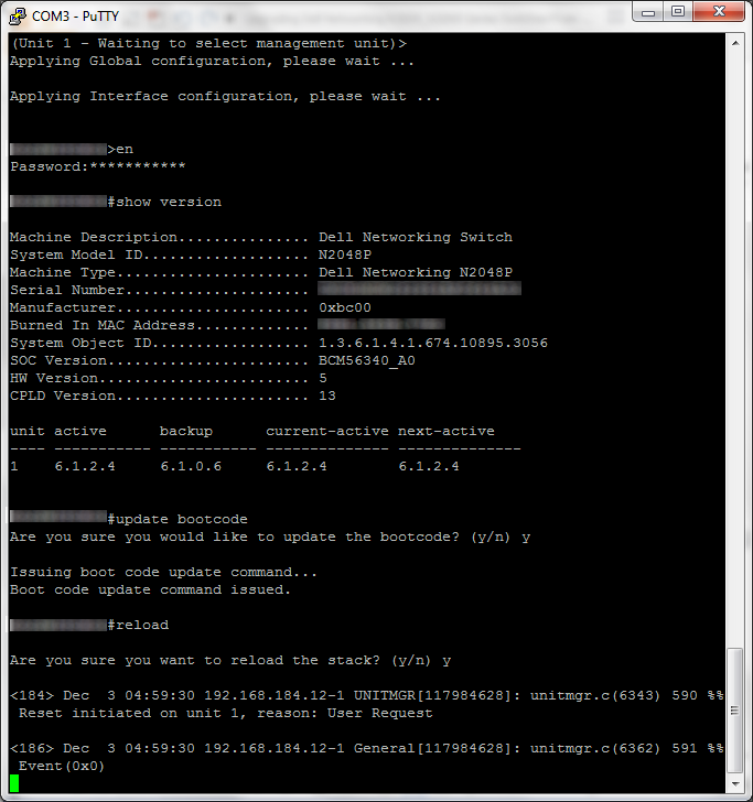
      N2000-3000 - update bootcode - reload
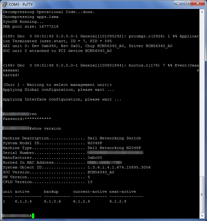
  9. Verify the build is now up-to-date
    1. console#> show version
      N2000-3000 - show version - active - 6_1_2_4
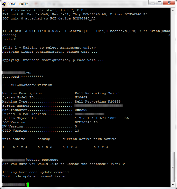
  10. Update the boot code
    1. console#> update bootcode
      N2000-3000 - show version - active - 6_1_2_4 - update bootcode
  11. Reboot the switch
    1. console#> reload
      N2000-3000 - update bootcode - reload

That should do it!

[Tutorial] Upgrading the firmware on a Cisco 5508 Wireless LAN Controller

This guide will show you what steps are needed to get your Cisco 5508 Wireless LAN Controller to the latest and greatest state.

  1. Download and install a TFTP Server program
    1. TFTPD is the recommend program to be used by Cisco.  It is a free and can be obtained from here: http://tftpd32.jounin.net/tftpd32_download.html
  2. Ensure your TFTP server instance is running and pointed to a directory of your choice.
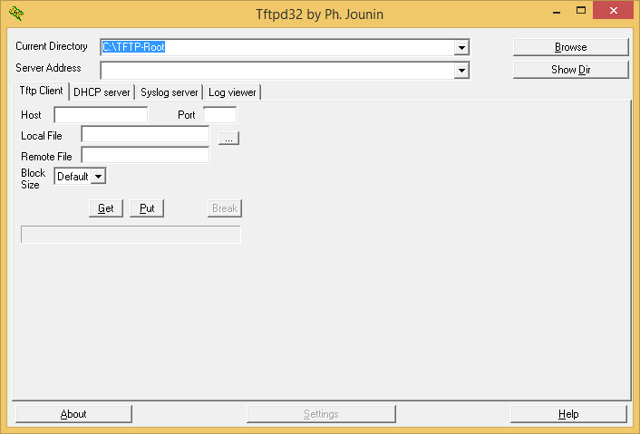
    In this tutorial, I will be using C:\TFTP-Root as my directory for hosting firmware.
    Tftpd32
  3. Ensure you have an inbound firewall created to allow incoming connections to your machine on UDP port 69 if you will be using the TFTP option.
    UDP 69 - TFTP - Windows Firewall with Advanced Security
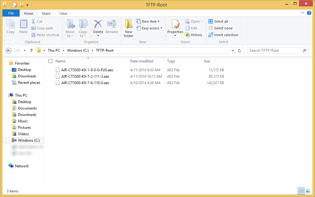
  4. Copy the firmware you want to transfer to the WLC to the TFTP server's directory
    TFTP-Server Firmware Directory
  5. Login to your Cisco WLC and select the Commands tab
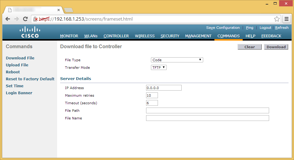
    Cisco WLC 5508 - Commands Tab
  6. Ensure the following settings are entered and then click the Download button
    1. File Type: Code
      Transfer Mode: TFTP
      IP Address: xxx.xxx.xxx.xxx (IP Address to your machine)
      File Path: / (Use a relative file path; for example, if your firmware was located at c:\tftp-server\cisco5508\AIR-CT5500-K9-7-6-110-0.aes, use /cisco5508/)
      File Name: AIR-CT5500-K9-7-6-110-0.aes (or whatever your firmware is called)
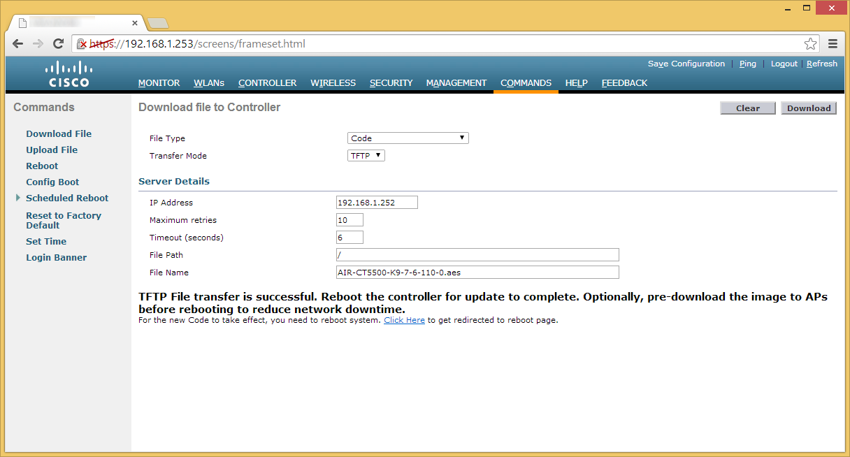
      TFTP File transfer is successful
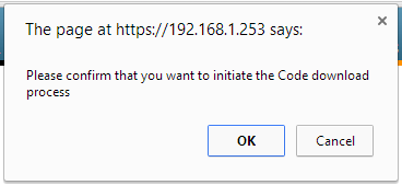
  7. Click OK when prompted to transfer the firmware
    Please confirm that you want to initiated the Code download process
  8. Once the firmware has finished updating, click on the Click Here link to reboot the WLC.
    TFTP File transfer is successful
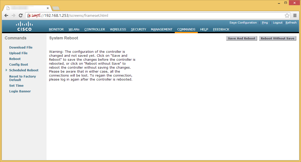
  9. On the System Reboot page, hit the Save and Reboot button.
    Cisco WLC 5508 - Commands - Save and Reboot
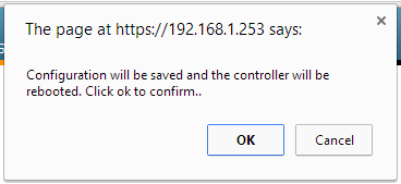
  10. Click OK on the Configuration will be saved and the controller will be rebooted prompt.
    Configuration will be saved and the controller will be rebooted - Click ok to confirm
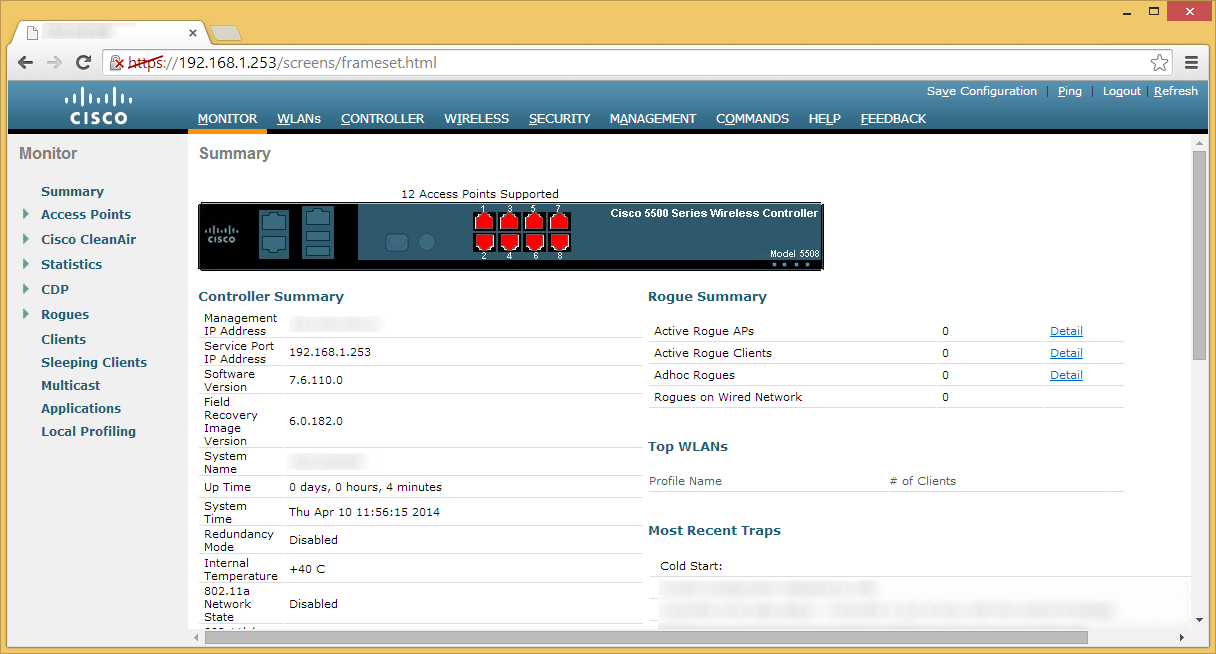
  11. Once the wireless LAN controller reboots, you should now be on the firmware version you provided.  You can verify on the Monitor page.
    Latest WLC firmware with outdated FUS
  12. At this point, you can can be done with your upgrade, however, it is highly recommended you also upgrade to the latest (or compatibile), version of the Field Upgrade Software (FUS) in additional to the WLC firmware (provided Cisco has a new version). The same steps to upgrade the FUS are of steps 6-10.
    1. Additional note, the FUS takes a considerable amount of time to upgrade the WLC.  It is normal for the FUS to take 30-50 minutes to upgrade after applying the firmware.  If you are not busy or intersted, you can watch the FUS upgrade various components if you console into the WLC during boot to keep an eye on things.
  13. Once the WLC and FUS firmware versions have been upgraded to their compatbile versions, you should be good to go! 🙂
Pushing firmware through CLI

If you wish to push the firmware manually via TFTP or FTP, you can use the following commands below (order doesn't matter as long as transfer download start is entered last).  The process is the same for uploading the firmware to the WLC, you only need to swap out the filename for either the FUS firmware or WLC firmware.

(Cisco Controller) > transfer download datatype code
(Cisco Controller) > transfer download mode tftp (can use ftp as well)
(Cisco Controller) > transfer download username user (only needed if using ftp)
(Cisco Controller) > transfer download password password (only needed if using ftp)
(Cisco Controller) > transfer download filename AIR-CT5500-K9-1-9-0-0-FUS.aes
(Cisco Controller) > transfer download path /
(Cisco Controller) > 
transfer download start


As of 4/14/2014, here are the latest firmware versions:

Release 1.9.0.0 for the Field Upgrade Software

Release 7.6.110.0ED for the Wireless LAN Controller


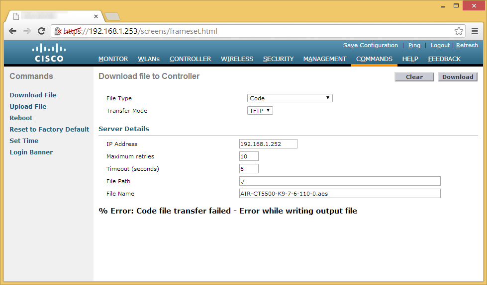
Notes: While upgrading our WLC from stock firmware, I received a strange error stating % Error: Code file transfer failed – Error while writing output file.  Please see my other blog post in regards to upgrading really old firmware on this device to the latest version: http://jackstromberg.com/2014/04/cisco-wlc-firmware-upgrade-error-code-file-transfer-failed-error-while-writing-output-file/

Cisco WLC Firmware Upgrade - % Error: Code file transfer failed - Error while writing output file

Symptom: When trying to upgrade your 5508 Wireless LAN Controller from an older firmware version (6.0.199.4 in my case), you receive the following error:

% Error: Code file transfer failed - Error while writing output fileError Code file transfer failed - Error while writing output file

Solution: When upgrading the firmware on the 5508, greater versions need to be applied incrementally.  Stock 5508 WLCs appear to be shipping with Software Version 6.0.199.4, the following firmware versions should be applied to reach the latest and greatest versions.

I applied the following upgrades to reach higher versions:

6.0.x  to 7.2.x ED

7.2.x ED to 7.x

Upgrading Network Policy Server from Server 2008 R2 to Server 2012 R2

Synopsis: This tutorial will cover a basic "upgrade" path to go from Server 2008 R2 to Server 2012 R2.  This tutorial assumes you have a single Network Policy Server and you are wishing to reuse the same machine name, IP, and settings.  In environments needing high availability, you will need to complete each of the steps below, adding/removing each server being upgraded from your network load balancer.

In a standalone instance, you will experience some downtime as you will have to retire the old machine and setup a new one.

Tutorial

  1. Login to your Server 2008 R2 NPS server
  2. Open up a command prompt with Administrative Privileges
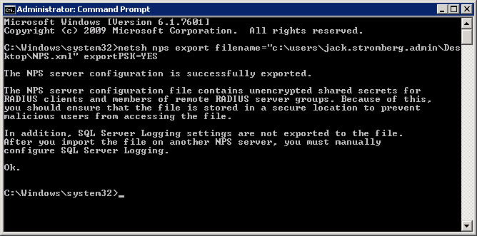
  3. Execute the following command
    1. netsh nps export filename="c:\users\YOURUSERNAME\Desktop\NPS.xml" exportPSK=YES
      netsh nps export
  4. Copy the NPS.xml file to your local machine
  5. Disjoin the NPS server from the domain
  6. Retire the machine
  7. Recreate a new Server 2012 R2 machine with the same name and IP address
  8. Join the Server 2012 R2 machine to the domain
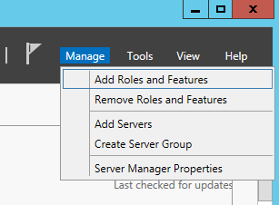
  9. Open up Server Manager and select Add Roles and Features
    Server 2012 - Manage - Add Roles and Features
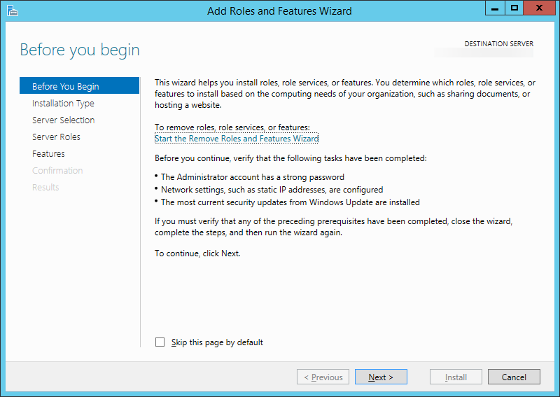
  10. Click Next > on the Before You Begin screen
    Add Roles and Features Wizard - Before you begin
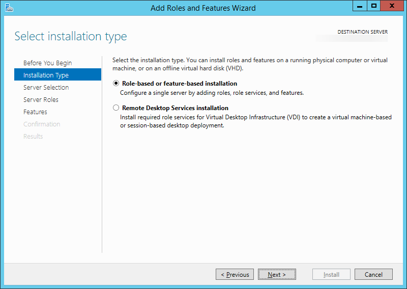
  11. Click Next > on the Installation Type screen
    Add Roles and Features Wizard - Select installation type
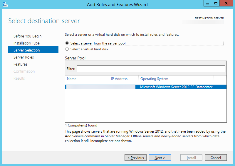
  12. Click Next > on the Server Selection screen
    Add Roles and Features Wizard - Select destination server
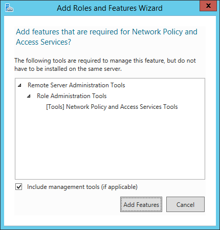
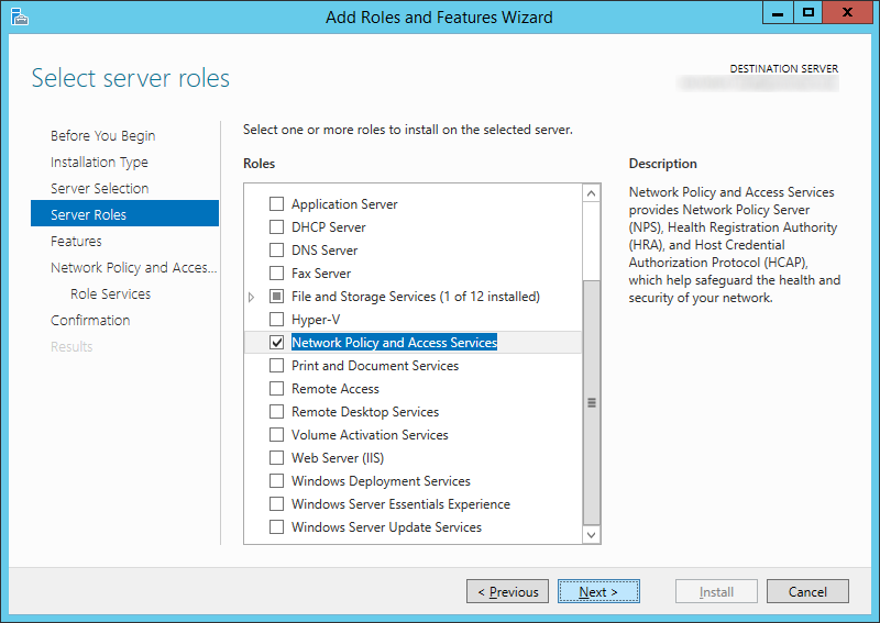
  13. Check Network Policy and Access Services (click Add Features when the screen pops up)
    Add Roles and Features Wizard - Network Policy and Access Services
    Add Roles and Features Wizard - Server Roles - Network Policy and Access Services
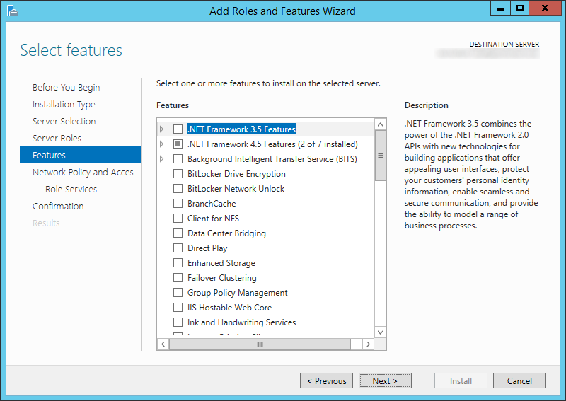
  14. Click Next > on the Features screen
    Add Roles and Features Wizard - Default - Network Policy and Access Services
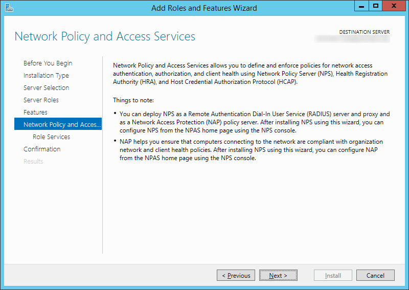
  15. Click Next > on the Network Policy and Access Services screen
    Add Roles and Features Wizard - Network Policy and Access Services Welcome
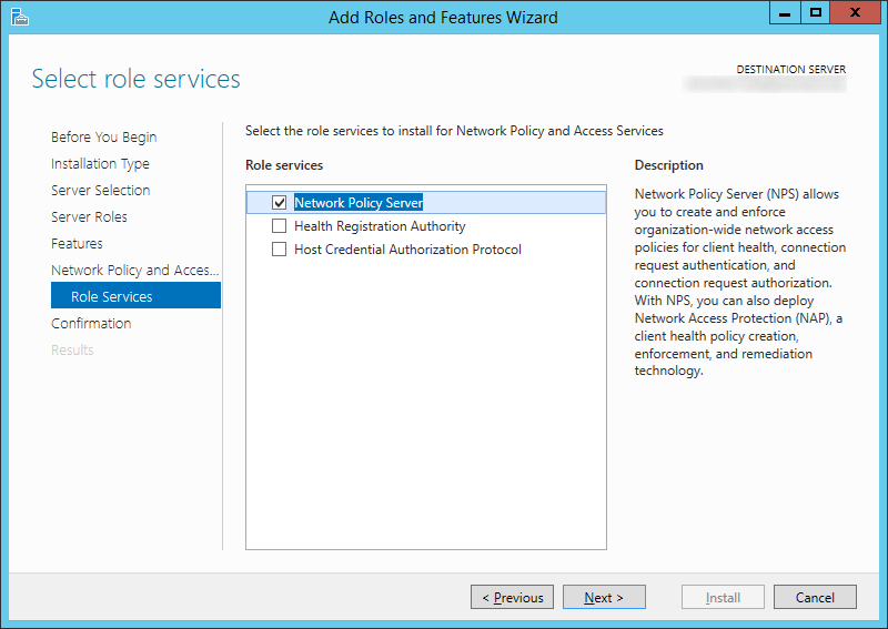
  16. Check Network Policy Server and click Next >
    Add Roles and Features Wizard - Role Services - Network Policy Server
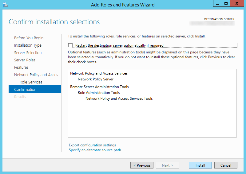
  17. Click Install
    Add Roles and Features Wizard - Network Policy and Access Services - Confirmation
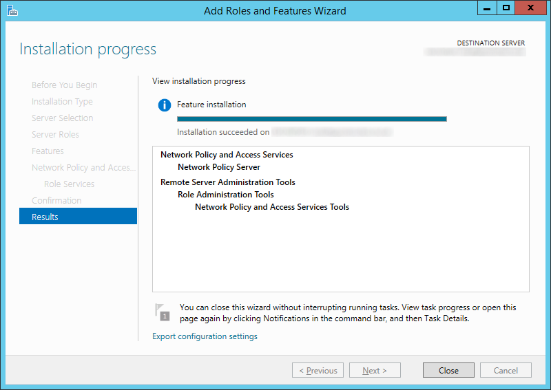
  18. Click Close once the installation has successfully completed
    Add Roles and Features Wizard - Network Policy and Access Services - Results
  19. Copy over your XML file from the old NPS server to your new Server 2012 R2 NPS server.
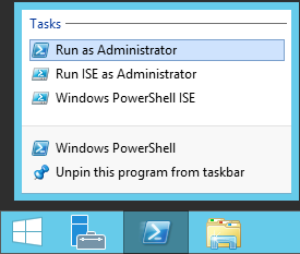
  20. Open up an administrative powershell prompt
    Server 2012 - PowerShell - Run as Administrator
  21. Execute the following command
    1. Import-NpsConfiguration -Path c:\users\YOURUSERNAME\Desktop\NPS.xml
      Server 2012 R2 - Powershell - Import-npsconfiguration
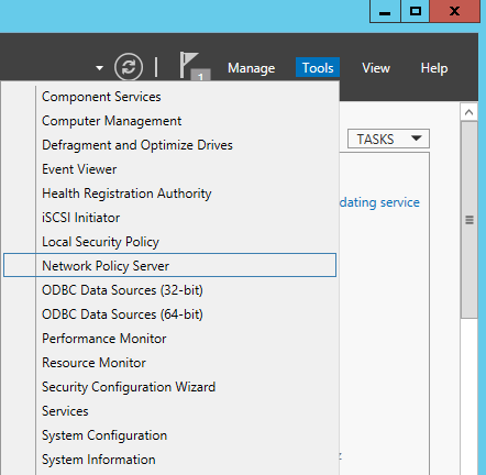
  22. Head over to Server Manager and select Tools -> Network Policy Server
    Server Manager - Tools - Network Policy Server
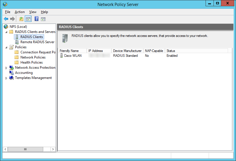
  23. Verify the rules imported (I selected RADIUS Clients and Servers -> RADIUS Clients to see if it imported my WLAN controller)
    Network Policy Server - RADIUS Clients
  24. Connect your machine to your wireless network! 🙂
[Tutorial] Configuring Direct Access on Server 2012 R2

This tutorial will cover deployment of Windows Server 2012 R2's latest version of DirectAccess.  While there are multiple ways to configure Direct Access, I tried to pull together what I believe are the best/recommended practices and what I believe would be a common deployment between organizations.  If you have any thoughts/feedback on how to improve this deployment, please leave a comment below.

Before beginning, if you are curious what DirectAccess is, here is a brief overview of what it is and what it will allow us to accomplish.

DirectAccess, also known as Unified Remote Access, is a VPN-like technology that provides intranet connectivity to client computers when they are connected to the Internet. Unlike many traditional VPN connections, which must be initiated and terminated by explicit user action, DirectAccess connections are designed to connect automatically as soon as the computer connects to the Internet. DirectAccess was introduced in Windows Server 2008 R2, providing this service to Windows 7 and Windows 8 "Enterprise" edition clients.
http://en.wikipedia.org/wiki/DirectAccess

Prerequisites

  • Domain Admin rights to complete the tutorial below
  • Windows Server 2012 R2 machine
    • Two network cards - One in your internal network, the other in your DMZ
    • Joined to your domain
    • Latest Windows Updates
      (seriously, apply these, there are updates released specifically for DirectAccess)
  • DMZ
  • PKI Setup (Public Key Infrastructure to issue self-signed certificates)
    • Custom template setup for issuing servers with an intended purpose of Server Authentication
    • Certificate auto-enrollment has been configured
  • Active Directory Security Group designated with Computer Objects allowed to use DirectAccess
  1. Login to your Server 2012 R2 server we will be using for installing the Direct Access
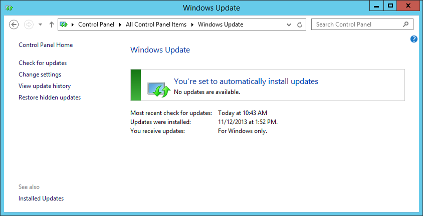
  2. Ensure all windows updates have been applied.
    Latest Windows Updates
  3. Open up Server Manager
    Server 2012 R2 - Server Manager
  4. Select Manage -> Add Roles and Features
    Server 2012 - Manage - Add Roles and Features
  5. Click Next > on the Before you Begin step
    Add Roles and Features Wizard - Before you begin
  6. Ensure Role-based or feature-based installation is checked and click Next >
    Add Roles and Features Wizard - Select installation type
  7. Select Next > on the Select destination server step
    Add Roles and Features Wizard - Select destination server
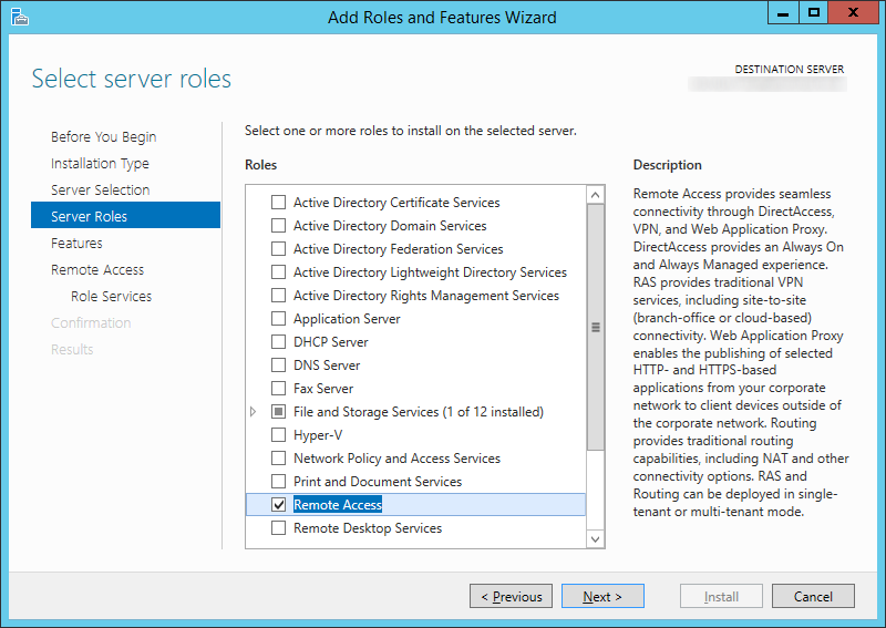
  8. Check Remote Access and click Next >Add Roles and Features Wizard - Server Roles - Remote Access
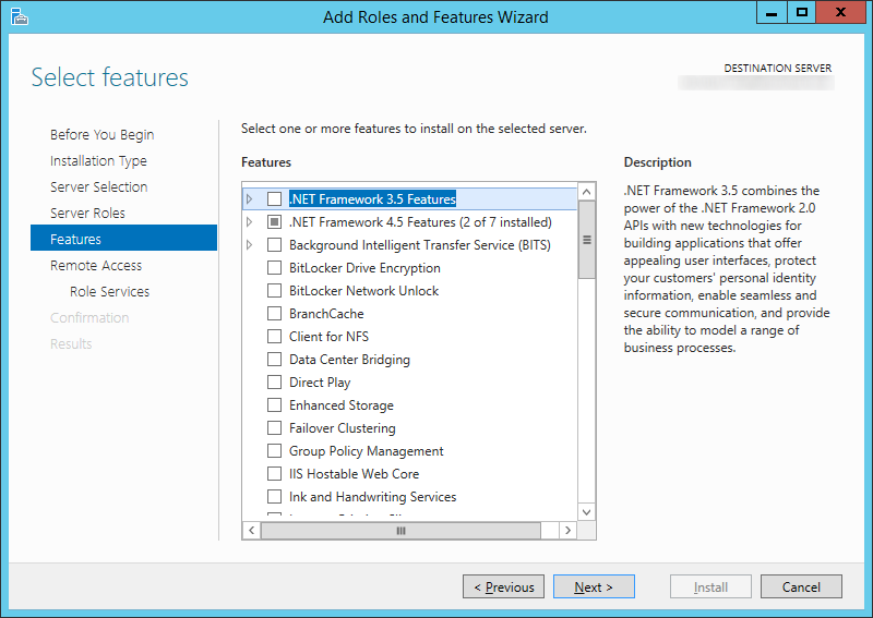
  9. Click Next > on the Select Features step
    Add Roles and Features Wizard - Server Roles - Features
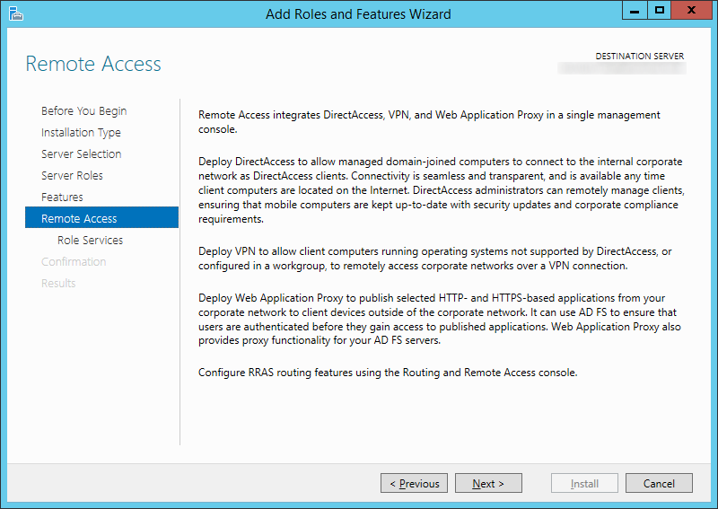
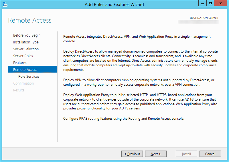
  10. Click Next > on the Remote Access step
    Add Roles and Features Wizard - Remote Access
  11. Check DirectAccess and VPN (RAS)
    Add Roles and Features Wizard - Remote Access
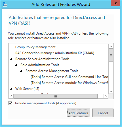
  12. Click the Add Features button on the dialog box that prompts
    Add Roles and Features Wizard - Remote Access - Add Features
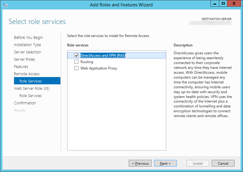
  13. Check DirectAccess and VPN (RAS) and then click Next >
    Add Roles and Features Wizard - Remote Access - Select role services
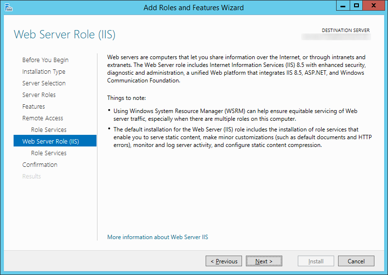
  14. Click Next > on the Web Server Role (IIS) page
    Add Roles and Features Wizard - Web Server Roll IIS
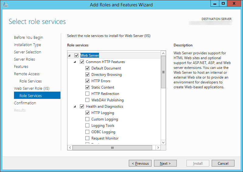
  15. Click Next > on the Role Services page
    Add Roles and Features Wizard - Web Server Roll IIS - Roll Services
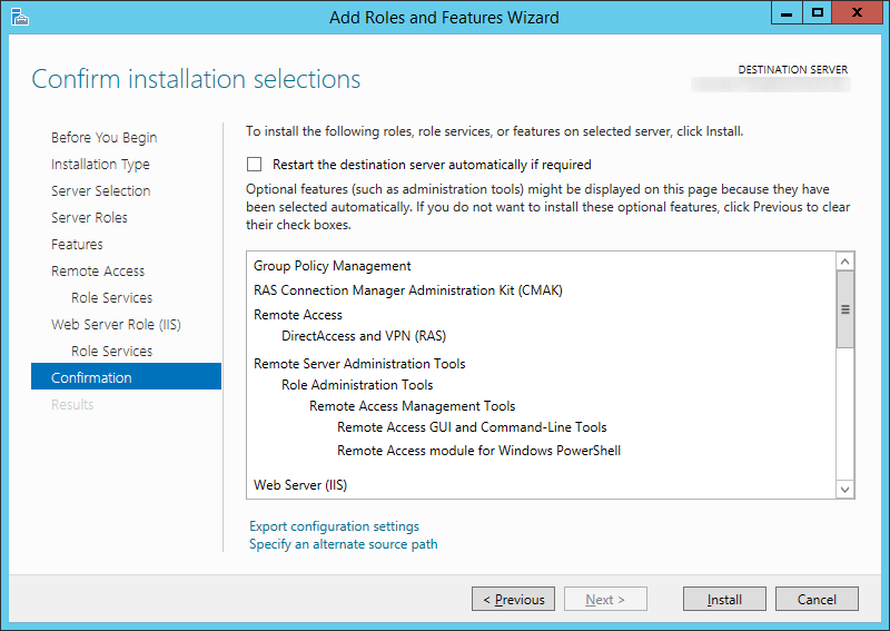
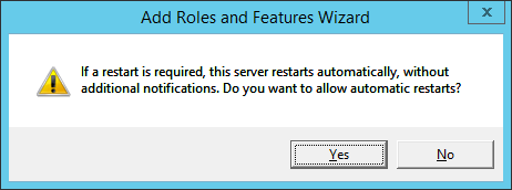
  16. Check the Restart the destination server automatically if required checkbox and click Yes on the dialog box.
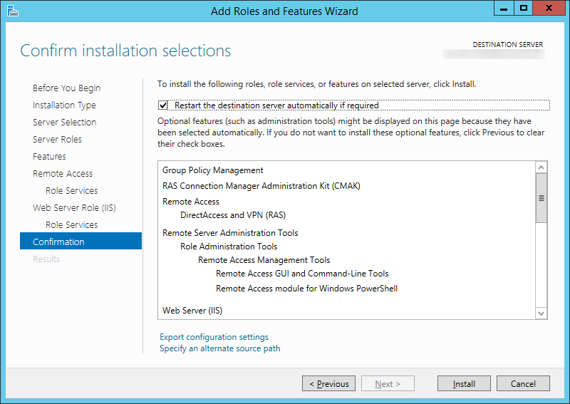
    Add Roles and Features Wizard - Confirm installation selections
    Add Roles and Features Wizard - Restart is required dialog
  17. Click Install
    Add Roles and Features Wizard - Confirm installation selections - Restart the destination server automatically if required
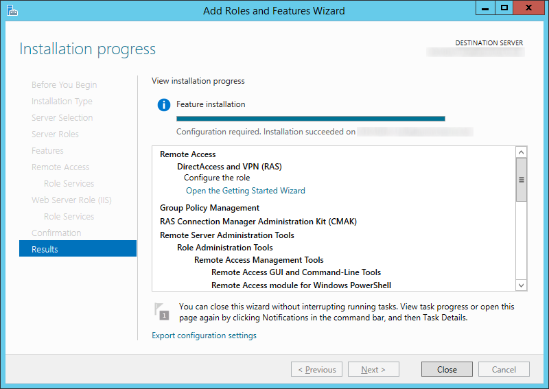
  18. Click Close when the install has completed
    Add Roles and Features Wizard - Results
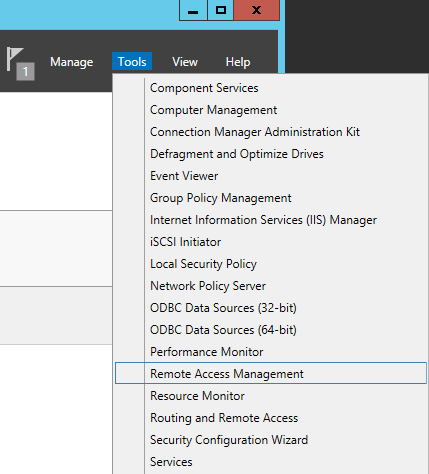
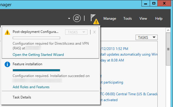
  19. Back in Server Manager, click on Tools -> Remote Access Management (You can ignore the warning icon, the Open the Getting Started Wizard will only do a quick setup of DirectAccess.  We want to do a full deployment).
    Server Manager - Tools - Remote Access Management
    Here is what the quick deployment looks like.  Don't click on this. Server Manager - Post-Deployment Configuration - DirectAccess
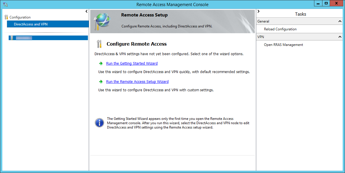
  20. On the Remote Access Management Console, click on DirectAccess and VPN on the top left and then click on the Run the Remote Access Setup Wizard.
    Remote Access Management Console - DirectAccess and VPN
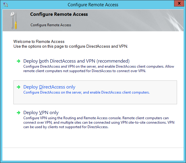
  21. On the Configure Remote Access window, select Deploy DirectAccess only
    Configure Remote Access - Deploy DirectAccess Only
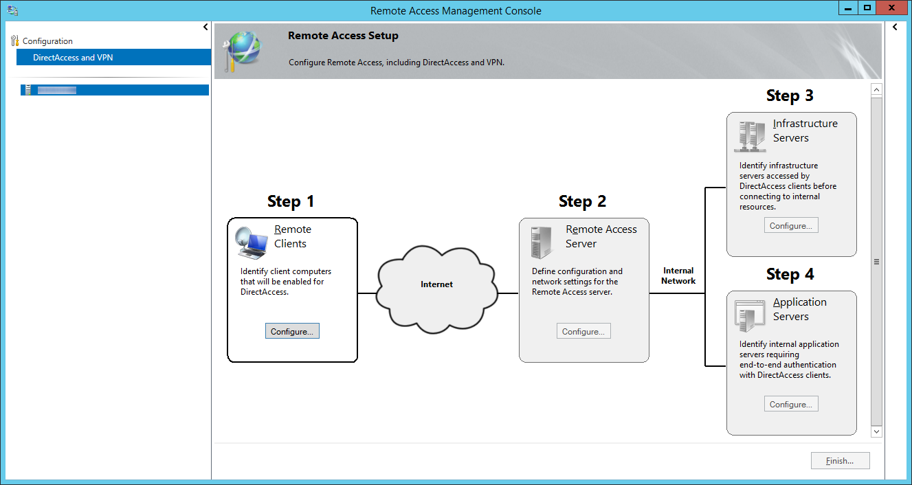
  22. Click on the Configure... button for Step 1: Remote Clients
    Remote Access Management Console - DirectAccess and VPN - Step 1 Remote Clients
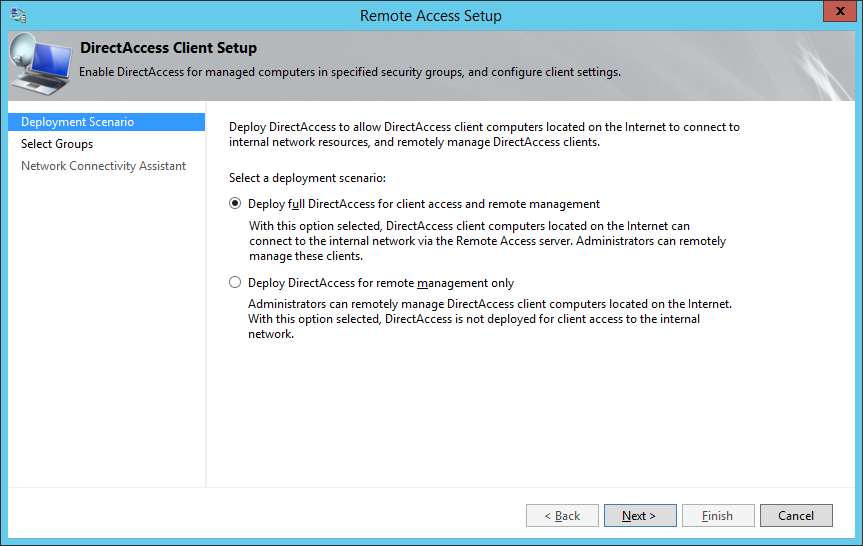
  23. Select Deploy full DirectAccess for client access and remote management and click Next >
  24. Remote Access Setup - Deploy full DirectAccess for client access and remote managment
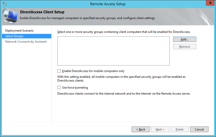
  25. Click on the Add... button
  26. Remote Access Setup - Select one or more security grups containing client computers that will be enabled for DirectAccess
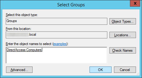
  27. Select the security group inside of Active Directory that will contain computer objects allowed to use DirectAccess and click OK
    Remote-Access-Setup-Select-Groups
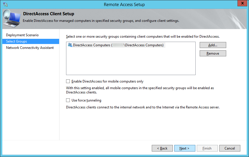
  28. Optionally, uncheck or check Enable DirectAccess for mobile computers only as well as Use force tunneling and click Next >
    1. If Enable DirectAccess for mobile computers is checked, WMI will query the machine to determine if it is a laptop/tablet.  If WMI determines the machine is not a "mobile device", the group policy object will not be applied to those machines in the security group.  In short, if checked, DirectAccess will not be applied to computers that are desktops or VMs placed inside the security group.
    2. If Use force tunneling is checked, computers will always use the direct access server when remote.  For example, if the user surfs the web to a public website like jackstromberg.com, the traffic will go through the DirectAccess tunnel and back to the machine, rather than directly to the ISP.  Generally, this is used for strict compliance environments that want all network traffic to flow through a central gateway.
    3. Remote Access Setup - Select Groups - Next
  29. Double click on the Resource | Type row
    1. What this step is trying to do is find a resource on the internal network that the client can "ping" to ensure the DirectAccess client has successfully connected to the internal network.
      Remote Access Setup - Network Connectivity Assistant - Resource Type
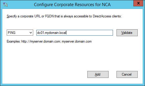
  30. Select whether you want the client to verify it has connected to the internal network via a HTTP response or network ping, optionally click the validate button to test the connection, and then click Add
    1. You may want to add a couple resources for failover testing purposes, however it isn't recommended to list every resource on your internal network.
      Remote Access Setup - Network Connectivity Assistant - Configure Corporate Resources for NCA
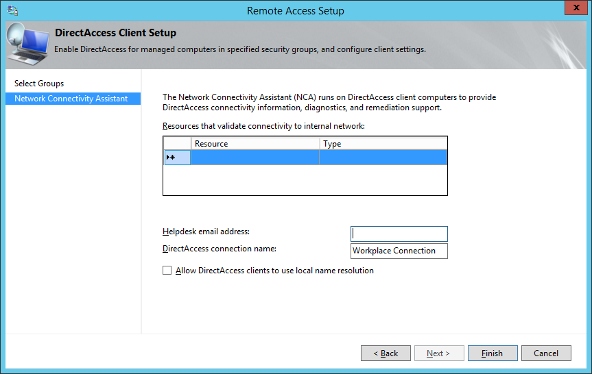
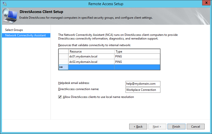
  31. Enter in your Helpdesk email address and DirectAccess connection name (this name will show up as the name of the connection a user would use), and check Allow DirectAccess clients to use local name resolution and click Finish.
    1. Based on what I could find, checking Allow DirectAccess clients to use local name resolution will allow the DirectAccess client to use the DNS server published by DHCP on the physical network they are connected to.  In the event the Network Location server is unavailable, the client would then use the local DNS server for name resolution; allowing the client to at least access some things via DNS.
      Remote Access Setup - Network Connectivity Assistant - Helpdesk email address - DirectAccess connection name
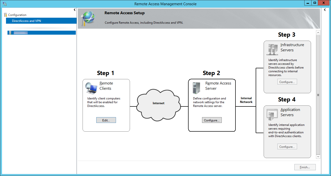
  32. Click on Configure... next to Step 2: Remote Access Server
    Remote Access Management Console - DirectAccess and VPN - Step 2 Remote Access Server
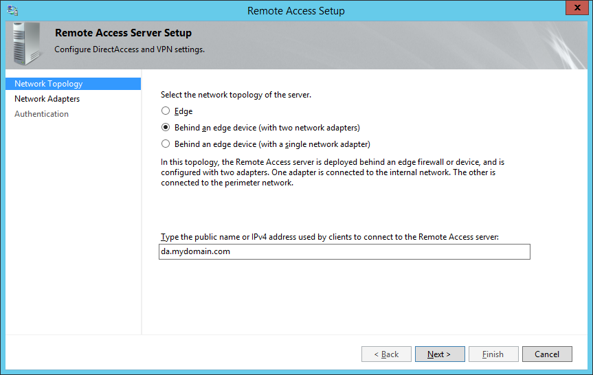
  33. On the Remote Access Server Setup page, select Behind an edge device (with two network adapters) and ensure you specify a public facing DNS record that DirectAccess will use to connect back to your environment, and then click Next >
    1. NOTE: By default, your domain's FQDN will be used, so if you have a .local domain, you will want to switch this to your actual .com, .net, .org, .whatever.
    2. As an additional side note, hereis some information from the following KB article on what the differences are between each of the topologies.  From what I gather, using the dual NIC configuration is Microsoft's best practice from a security standpoint.
      • Two adapters—With two network adapters, Remote Access can be configured with one network adapter connected directly to the Internet, and the other is connected to the internal network. Or alternatively the server is installed behind an edge device such as a firewall or a router. In this configuration one network adapter is connected to the perimeter network, the other is connected to the internal network.
      • Single network adapter—In this configuration the Remote Access server is installed behind an edge device such as a firewall or a router. The network adapter is connected to the internal network.

    Remote Access Server Setup - Network Topology

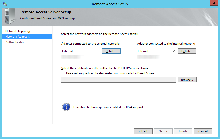
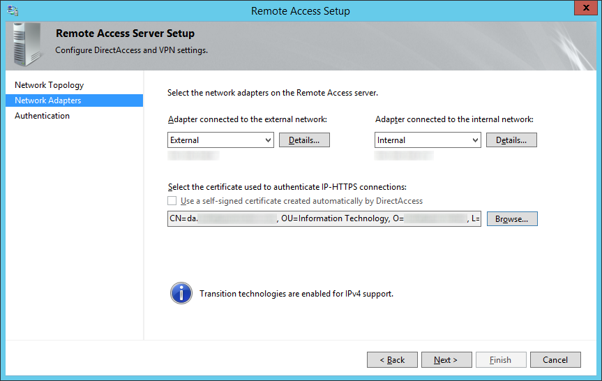
  34. On the Network Adapters step, select your External (DMZ) and Internal (LAN) adapters.Remote Access Server Setup - Network Adapters - External Internal
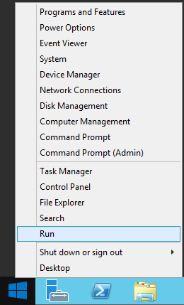
  35. Leave the Remote Access Setup screen open and right click on Start button and select Run
    Server 2012 - Run
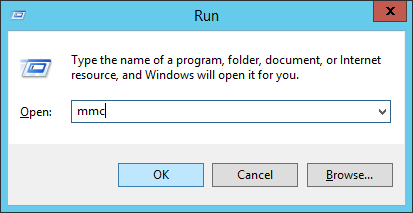
  36.  Type mmc and select OK
    Server 2012 - Run - mmc
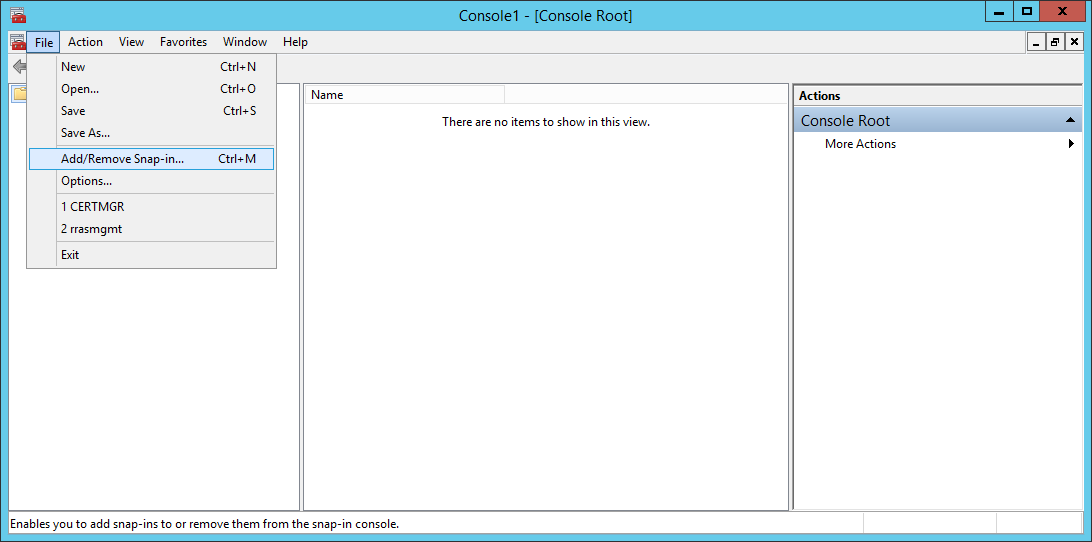
  37. Click File -> Add/Remove Snap-in...
    mmc - File - Add-Remove Snap-in
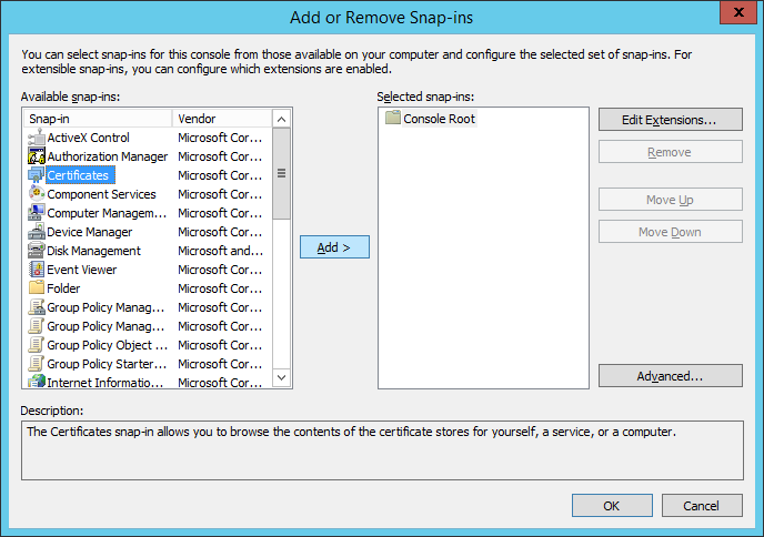
  38. Select Certificates and click Add >
    Add or Remote Snap-ins - Certificates
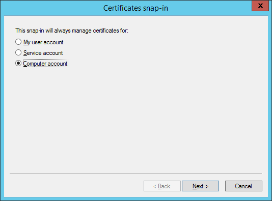
  39. Select Computer account and click Next >
    Certificates snap-in - Computer Account
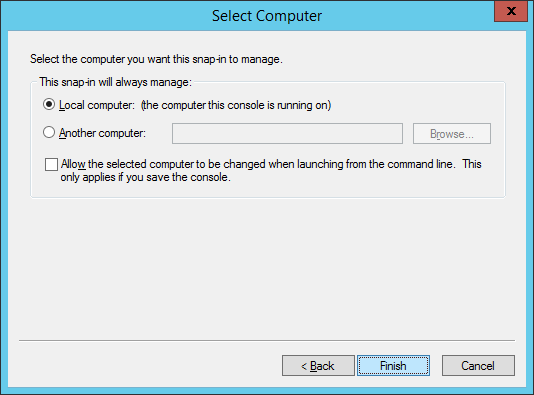
  40. Ensure Local Computer is selected and click Finish
    Certificates snap-in - Select Computer
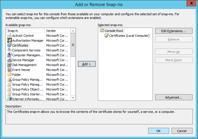
  41. Click OK on the Add or Remove Snap-ins machine
    Add or Remove Snap-ins - Certificates - Local Computer
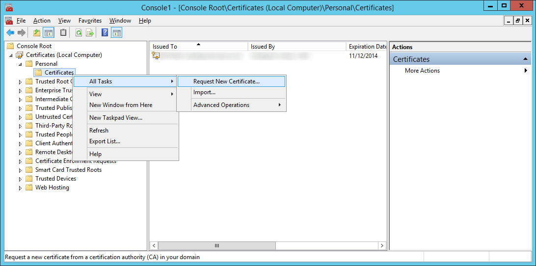
  42. Expand Certificates (Local Computer) -> Personal -> Certificates, right click on Certificates and select Request New Certificate...
    Certificates - All Tasks - Request new certificate
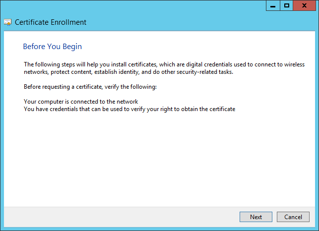
  43. Click Next on the Before You Begin screen
    Certificate Enrollment - Before You Begin
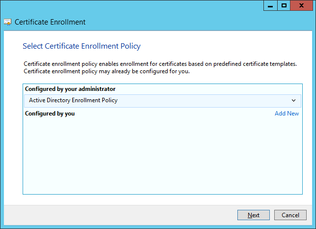
  44. Click Next on the Select Certificate Enrollment Policy
    Certificate Enrollment - Select Certificate Enrollment Policy
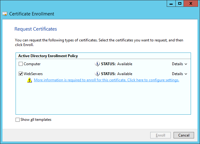
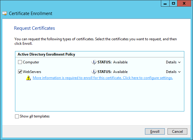
  45. Select your template that will support server authentication and click More information is required to enroll for this certificate.  Click here to configure settings.
    Certificate Enrollment - Request Certificates

    1. Note: The WebServers enrollment policy is not something out of the box configured by Microsoft.  You will need to manually login to your certificate authority, duplicate the Web Servers template with the settings you wish, ensure your usergroup can Enroll for a certificate, and then publish it to AD.
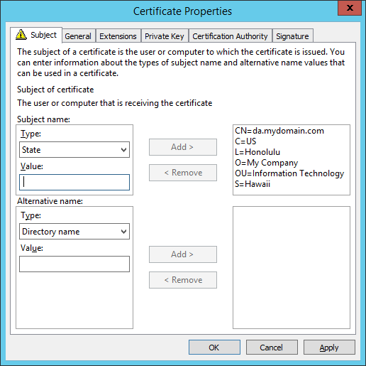
  46. On the Subject tab, enter the following values (substituting in your company's information):
    Common name: da.mydomain.com
    Country: US
    Locality: Honolulu
    Organization: My Company
    Organization Unit: Information Technology
    State: Hawaii
    Certificate Enrollment - Certificate Properties - Subject Tab
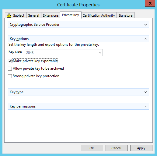
  47. On the Private Key tab, expand Key options and check Make private key exportable.  Click Apply when done.
    Certificate Enrollment - Certificate Properties - Private Key Tab
  48. Click Enroll.
    Certificate Enrollment - Request Certificates - Enroll
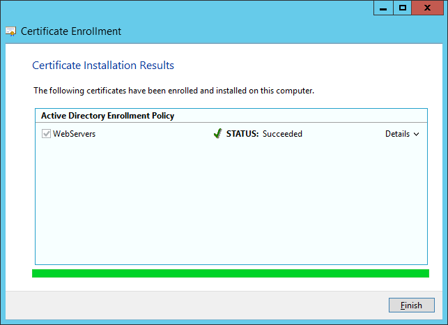
  49. Click Finish.
    Certificate Enrollment - Certificate Installation Results
  50. Go back to the Remote Access Setup screen and click Browse...
    Remote Access Server Setup - Network Adapters - External Internal
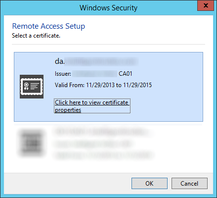
  51. Select your da.mydomain.com certificate we just created and click OK.
    Remote Access Setup - Select a certificate
  52. Click Next >
    Remote Access Setup - Network Adapters - External Internal Certificate
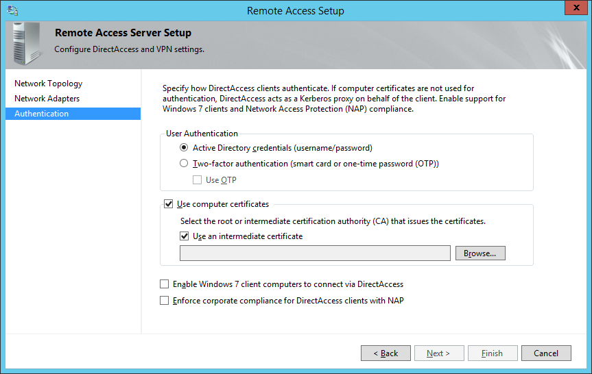
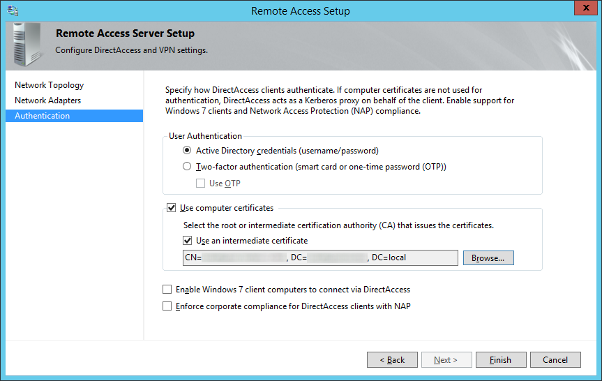
  53. Check Use computer certificates and check Use an intermediate certificate and then click Browse...
    Remote Access Setup - Authentication - Active Directory Credentials
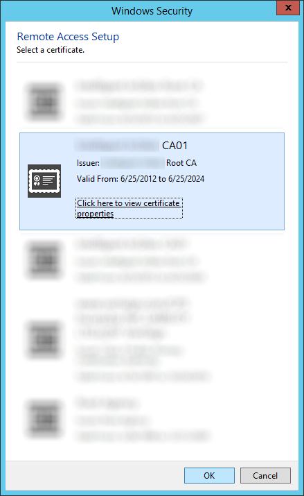
  54. Select the certificate authority that will be issuing the client certificates and click click OK
    Remote Access Setup - Authentication - Select a certificate
  55. Optionally, you may enable Enable Windows 7 client computers to connect via DirectAccess as well as Enforce corporate compliance for DirectAccess clients with NAP.  Note: Configuring these two options are not covered in the scope of this tutorial.  Click Finish when done.
    Remote Access Setup - Authentication - Finish
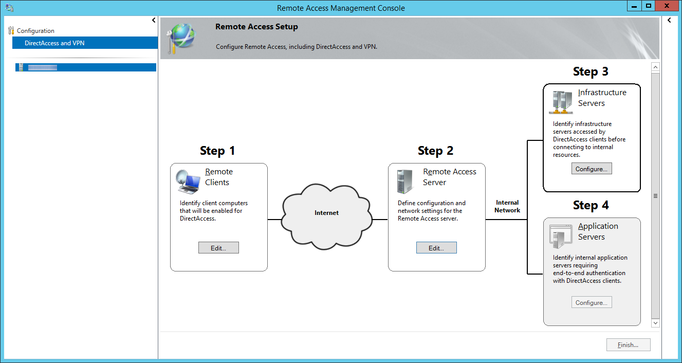
  56. Click on Configure... next to Step 3: Infrastructure Servers
    Remote Access Management Console - DirectAccess and VPN - Step 3 Infrastructure Servers
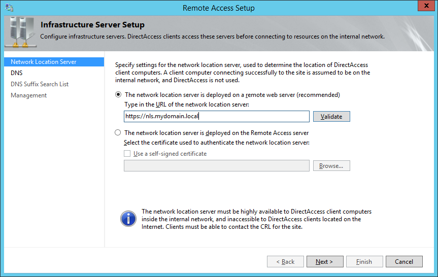
  57. On the Remote Access Setup screen, check The network location server is deployed on a remote web server (recommended), type in the website address to the Network Location Server, and click Next >
    1. So for whatever reason, there aren't many articles explaining what exactly the network location server is and how to set it up.  From what I gather, the Network Location Server is merely a server with a website running on it that the client can contact to ensure it has reached the internal network.  The webpage can be the default IIS webpage; just ensure the website is NOT accessible externally.
      Remote Access Setup - Network Location Server
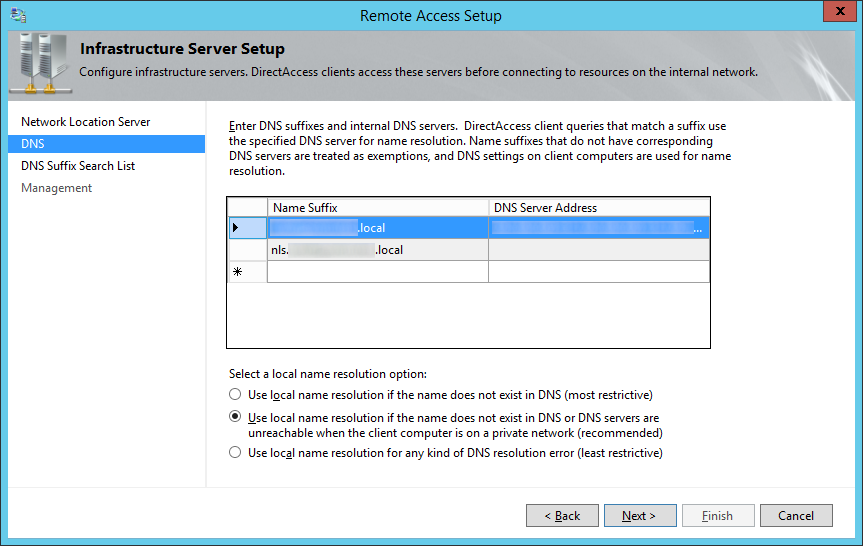
  58. Specify any additional DNS servers you wish to use for name resolution, ensure Use local name resolution if the name does not exist in DNS or DNS servers are unreachable when the client computer is on a private network (recommended) is checked and click Next >
    Remote Access Setup - Infrastructure Server Setup - DNS
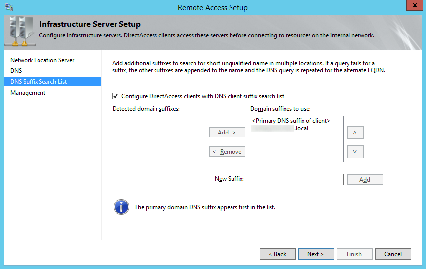
  59. Check Configure DirectAccess clients with DNS client suffix search list, ensure your local domain's suffix has been added, and click Next >
    Remote Access Setup - DNS Suffix Search List
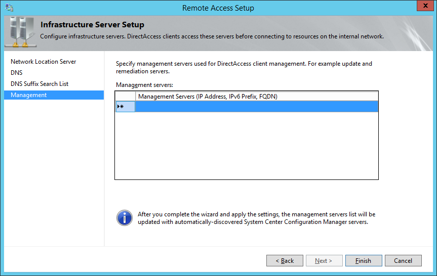
  60. Click Finish on the Management page.
    Remote Access Setup - Management
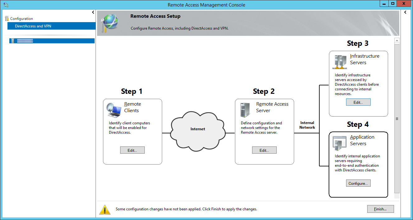
  61. Click the Configure.... button on Step 4: Application Servers
    Remote Access Management Console - Step 4 Application Servers
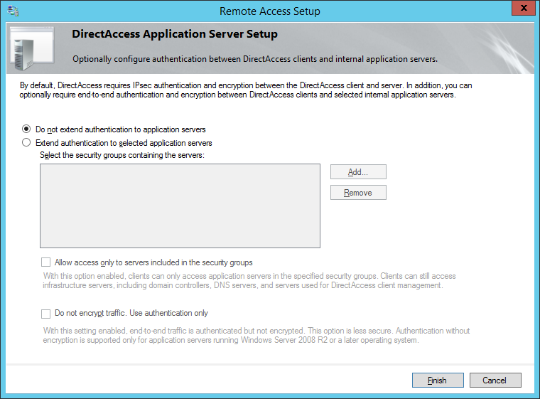
  62. Check Do not extend authentication to application servers and click Finish
    Remote Access Setup - Do not extend authentication to application servers
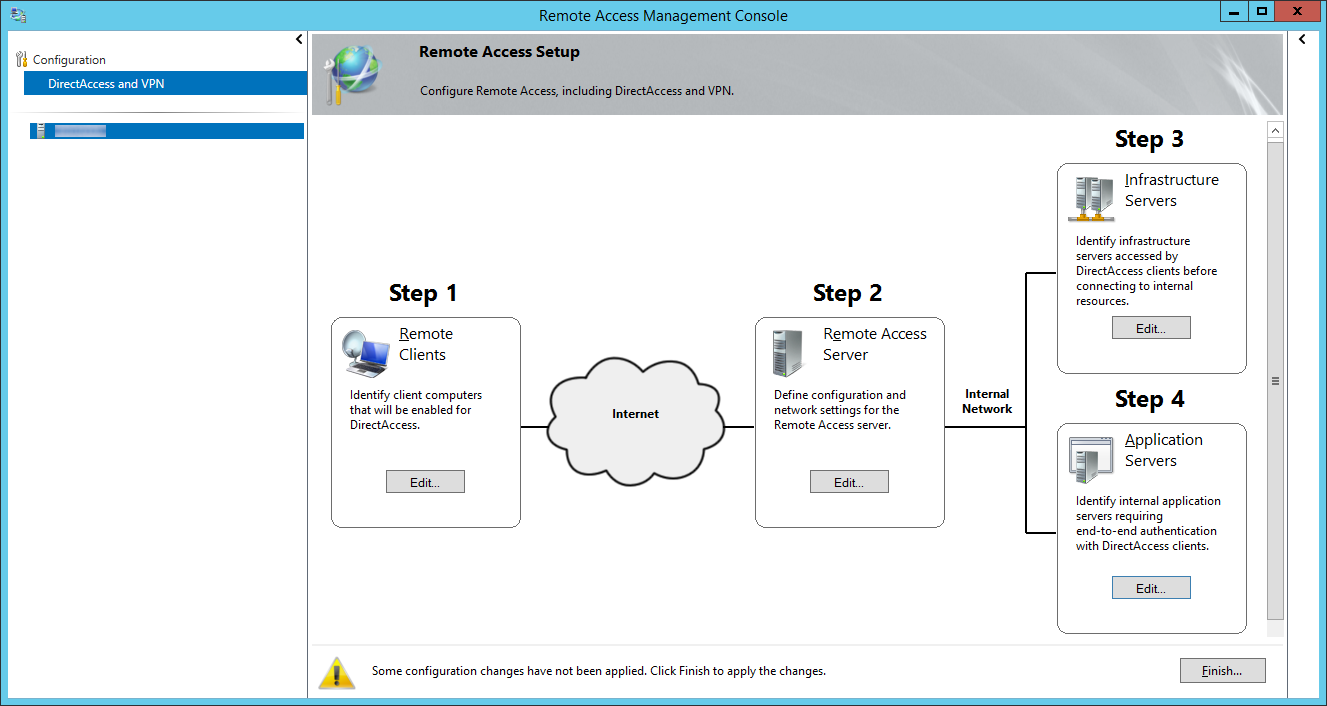
  63. Click Finish... on the Remote Access Management Console page
    Remote Access Management Console - Finish
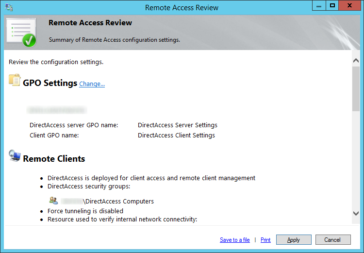
  64. Click Apply on the Remote Access Review page
    Remote Access Review - Summary of Remote Access configuration settings
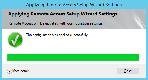
  65. Click Close once direct access has successfully finished deploying
    Apply Remote Access Setup Wizard Settings - The configuration was applied successfully
  66. Login to one of your Windows 8.X Enterprise machines that is inside of your DirectAccess Compuers security group and run a gpupdate from command line to pull down the latest group policy.
  67. At this point, you should now be able to login to your network via DirectAccess!

NOTES:

Here is a pretty good resource from Microsoft on helping plan your DirectAccess deployment.  Once you click on the link, in the bottom left corner, you will find two steps to some good KB articles: http://technet.microsoft.com/en-us/library/jj134262.aspx

Here is another article from Microsoft with a more indepth explanation about where to place the Network Location Server: http://technet.microsoft.com/en-us/library/ee382275(v=ws.10).aspx