There are a ton of old Teslas out there running Autopilot v1 (AP1), and they fall further behind in assisted-driving capability every year. AP1 felt ultra futuristic in its day, but it’s starting to become outclassed even by the lane assist shipping in everyday non-Tesla cars.
One of the biggest reasons I opted to seek an upgrade was the ability to remove the notorious “Tesla NAG”. While I get checking if the driver is paying attention is critical for safety, the way Tesla did it in AP1 was less than ideal by having to apply torque to the steering wheel, even if you are alert and watching the road ahead of you. In addition, the driving capabilities of AP1 on unmarked roads, aggressive curves, phantom braking, etc. make for a significantly less confident driving experience in AP1 and feel dated compared to newer vehicles today.
openpilot – make driving chill
Revive your car with the open source software openpilot, maintained by the company Comma AI! comma.ai — make driving chill
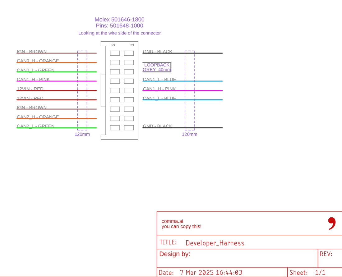
While Comma AI does not officially support old Tesla vehicles there are several forks for older Teslas to use openpilot and while Comma AI doesn’t provide an official wiring harness for older Tesla cars, they do provide a developer harness where you can make your own.
You can grab a harness for the vehicle from a developer in the openpilot community, who has helped try to maintain a fork of openpilot (which we’ll talk about later on). This makes installing the Comma 4 significantly easier by bringing peace of mind it’s correct and kick back support to the maintainer for their contributions to the fork for the older Tesla vehicles.
That being said, I went down the road of trying to DIY this myself for a few reasons: 1) I wanted to learn. 2) There have been many contributors to the Tesla AP1 effort and at time of writing this, there is only one individual making harnesses. If that individual decides to take on a new project, that makes new harnesses for Tesla AP1 vehicles impossible to source (supply chain risk). In the spirit of open source, IMO, the harness details should be available to keep the vehicle support available for future reference. 3) I wanted to use Comma supplied products as much as possible to have as close to what an official solution might be as possible. 4) I had many of the tools needed to make the harness and could do it for significantly less.
When starting the project, cost wasn’t originally my concern, but I was lucky and was able to pick up their official developer harness for $50 on sale and with sourcing the parts and ultimately was able to make it for under $100. The prebuilt harness was > $250 and my understanding at the time is it would have shipped from Europe, so it would have likely gone over $300 with tariffs with that assumption (although they have some stock in the USA I found out later on).
While a cheaper harness sounds great, one big note is if you go down the DIY route, don’t expect the Comma community to help. The folks that really understand this kind of stuff in the unsupported Tesla community really laid it on thick that I should give up and just buy the harness.
IMO, if you have the time and patience it was an interesting project and I learned a lot on the electrical side and comma side debugging the pin configuration.
Nonetheless, if you do this DIY, don’t expect much help. If you just want your car to work, buy the harness, it’s worth it. If you have some background in software development and electrical engineering, then here’s my learnings if you want to take a similar venture; but proceed at your own risk. I’m not responsible if you short out any components of your car.
Acquiring the parts for the harness if you DIY this
Qty 1: Electrical tape – Ideally, you could also use heat shrink tubing if you have some that’s 1.25″ wide.
Misc from Amazon
Qty 1: Wiring harness tape – not required, but can help with longevity of your cable.
Note: this guide assumes you have solder, soldering iron, and wire strippers on hand. I’d recommend an adjustable wire stripper as getting the lengths to the connectors can be tricky by hand, but if you are buying this just to make the cable, you may as well buy the prebuilt harness since you are likely getting close to breaking even: 12 40 200 Knipex Tools LP | Wire Strippers and Accessories | DigiKey
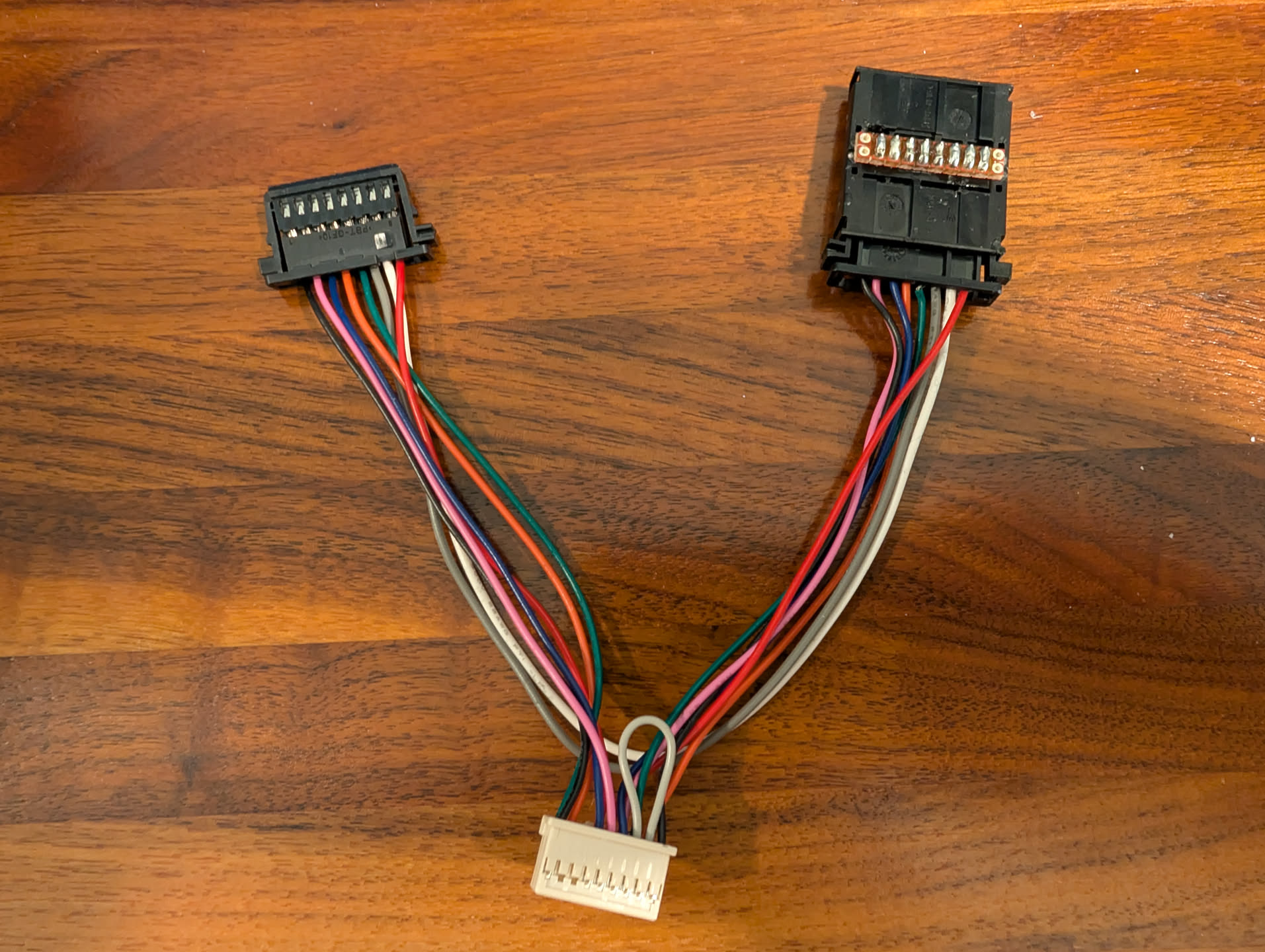
Pulling it altogether, you get this as the secret sauce to build the harness:
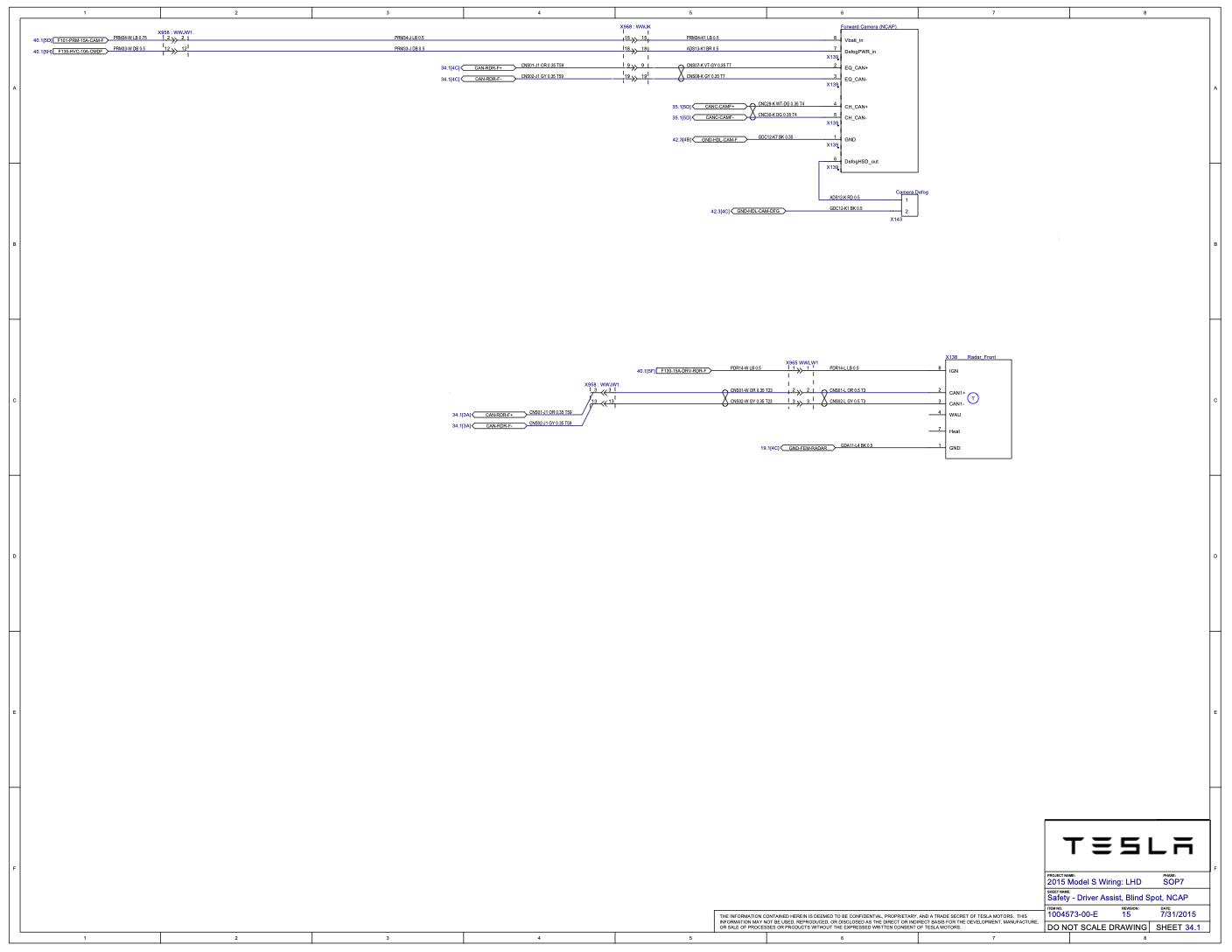
This branch of your harness is what receives the connector from the car (connector originally going to the Forward Camera (NCAP) port).
Connector to car (MQS 8P PLUG HSG) [Connects to the Tesla cable]
Signal
Comma DEVELOPER harness pin
Pin 8
GND
Pin 1
Pin 7
Radar CAN +
Pin 8
Pin 6
Radar CAN −
Pin 7
Pin 5
Camera CAN +
Pin 4
Pin 4
Camera CAN −
Pin 6
Pin 3
DefogHSD_OUT
Passthrough to mirror pin 6
Pin 2
DefogPWR_in
Passthrough to mirror pin 7
Pin 1
+12V
Pin 10
This branch of your harness is what plugs into the Forward Camera (NCAP) port.
Connector to mirror (MQS 8P PLUG HSG) [Connects to mirror port]
Signal
Comma DEVELOPER harness pin
Pin 1
GND
Pin 17
Pin 2
Radar CAN +
Pin 9
Pin 3
Radar CAN −
Pin 11
Pin 4
Camera CAN +
Pin 16
Pin 5
Camera CAN −
Pin 18
Pin 6
DefogHSD_OUT
Passthrough to car pin 3
Pin 7
DefogPWR_in
Passthrough to car pin 2
Pin 8
+12V
Pin 12
Pin 3 and 5 are looped on the comma developer harness connector (this is standard to the dev harness as-is)
The two IGN cables (brown cables at time of writing) that come with the dev harness you can remove as they won’t be used. You can use a tiny flat head screwdriver to gently lift the flap holding the connector to the cable up while pulling on the cable to slide them out.
For Pin 6 and 7 that passthrough to other connector, those map to the defog control of the mirror and can skip connecting to the Comma developer harness. The developer harness uses 26 AWG wire if you want to match their wire size. I used White and Dark gray cables to try and differentiate from the colors used in the Comma dev harness, but the color of shielding isn’t going to make a difference electrically lol
One note about this, be very very very careful you do not mix up the 12v pins with another position when building your harness. If you send 12v down your CAN buses, that will not be good. Use a multimeter to triple check. I was ultra surprised to find that Tesla had a red wire on their harness and it didn’t carry 12v; rather the “blue” wire is what actually carried 12v. Going simply by the color codes would have given me a bad day, so DO NOT make any assumptions.
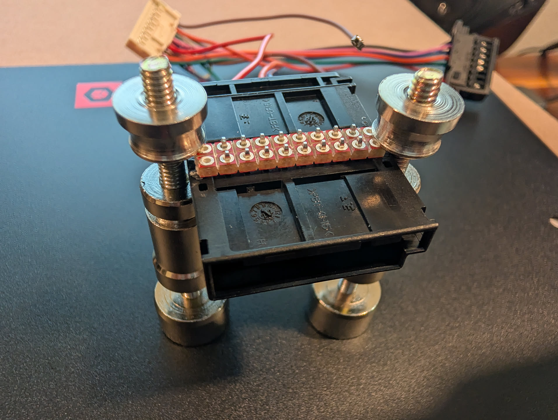
When building my harness, I terminated both the “to car” and “to camera” cables with the MQS 8P plugs. Connecting the cable from the car to the comma, I placed both MQS HDR 8P ASSY back-to-back on the protoboard and soldered the pins together. This allowed me a secure connection between the car and comma harness. Unfortunately, TE Connectivity doesn’t have the receiving connector without it being mounted to a PCB board, so double connector it was. Given vibration and force from accelerating / braking, I’d recommend locking connectors over the screw down blocks to prevent wires from coming loose.
Harness Creation
Break away 2 rows of 10 pins from your protoboard. If having a tough time snapping the protoboard apart, you can use a utility knife or exacto knife to score the area you want to snap; then use a needle nose pliers to wiggle the board back and forth until it breaks away. I used 10 pins worth, with one pin on each side unused, to give the connector a little more rigidity. Place the HDR 8P ASSY adapters back to back and solder them together.
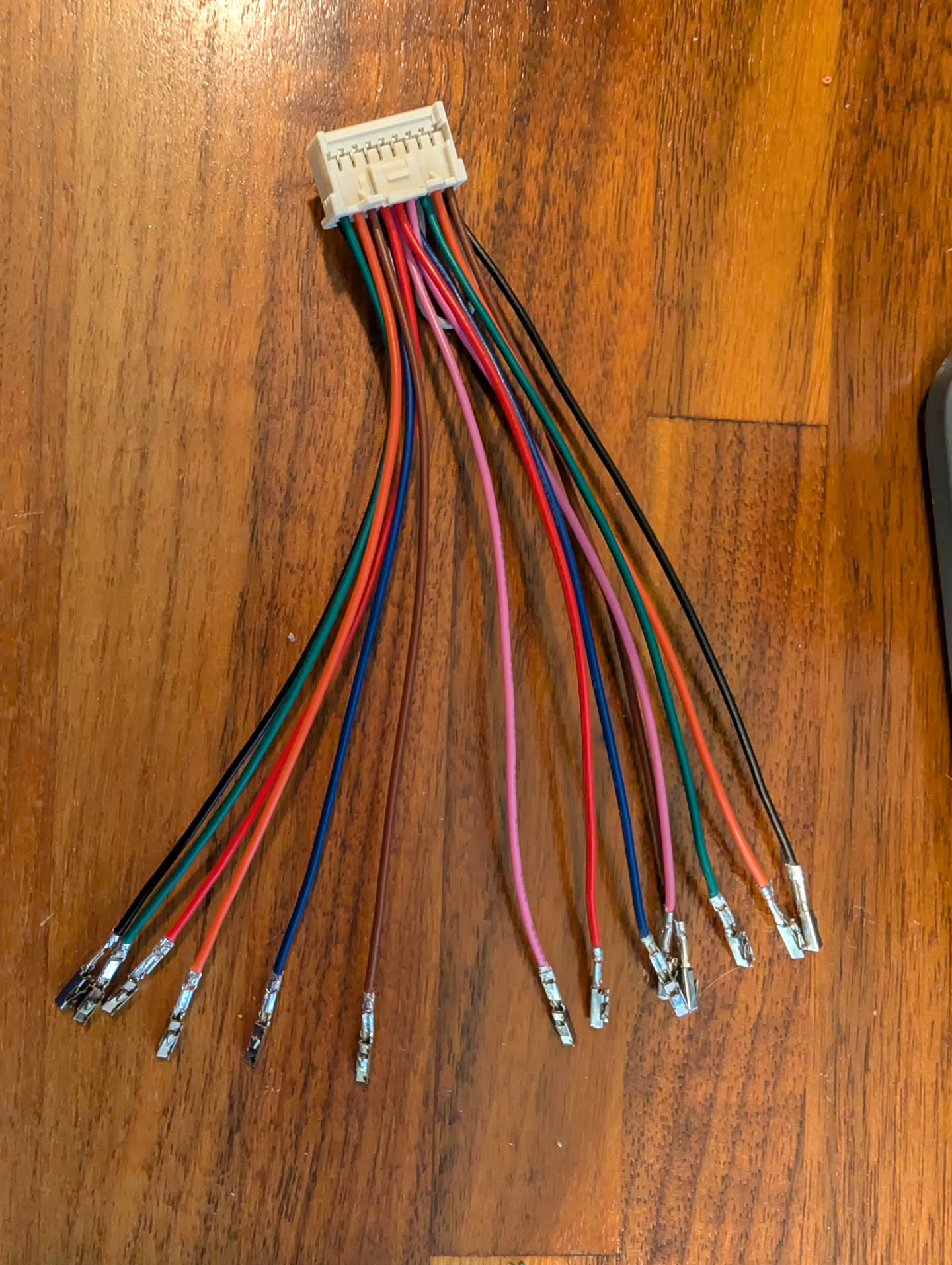
Remove the 2 IGN pins from the comma harness since they won’t be used and add the MQS rectangular pins to each of the wires needed for the harness.
Connect the wires to each of the MQS 8P PLUG HSG adapters.
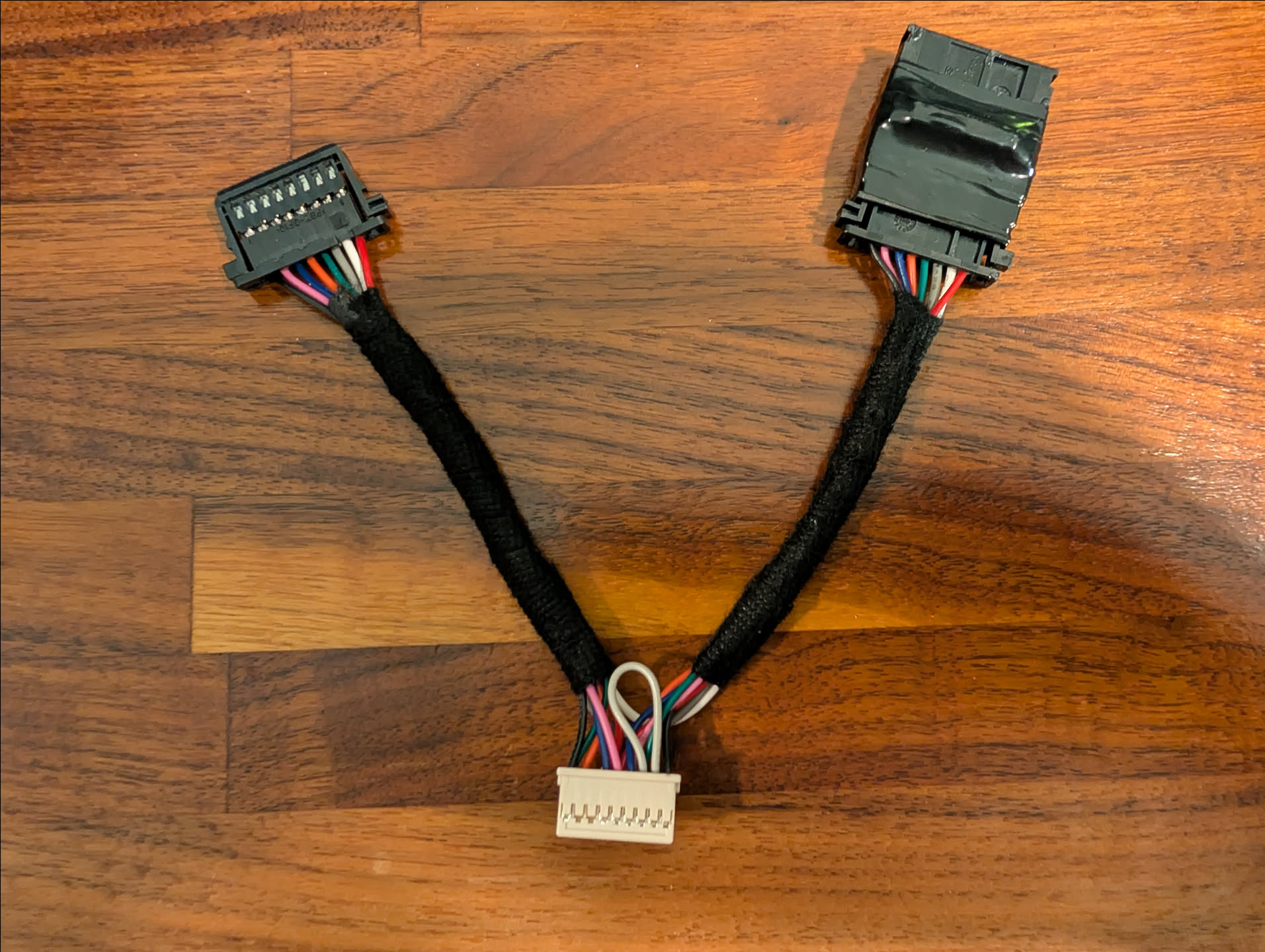
Add the fabric tape around the two branches of the harness and added electrical tape around the two HDR 8P ASSY adapters to insulate the soldered pins.
Final harness should look something like this:
Mount the Comma 4 Bracket
Before you pull apart your mirror, I would recommend mounting the Comma 4 bracket. Sit how you would normally in your seat, then hold the device up. The camera can be partially blocked by the mirror, but not fully. I saw a guide that said use 3 fingers down and you should be good. I did more like 4-5, since 3 had the entire device completely blocked by the mirror. Once your Comma 4 is mounted, remove the Comma 4 itself from the device, leaving just the mount on your windshield. One thing to make sure is to make sure the yaw (left and right balance) of the unit is as close as level as possible; you have roughly 4 degrees of skew and it’s nearly impossible to adjust once you stick the device, so have someone take a look on the outside of the windshield to gauge if it looks aligned properly.
Install the harness
To install the harness you will need to remove the front mirror assembly. Official instructions can be found on Tesla’s website here:
If you prefer a YouTube video, this video was helpful on understanding how to remove the mirror (don’t go past moving the mirror):
Mount the Comma 4 and Connect the harness
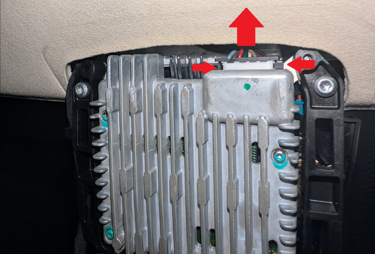
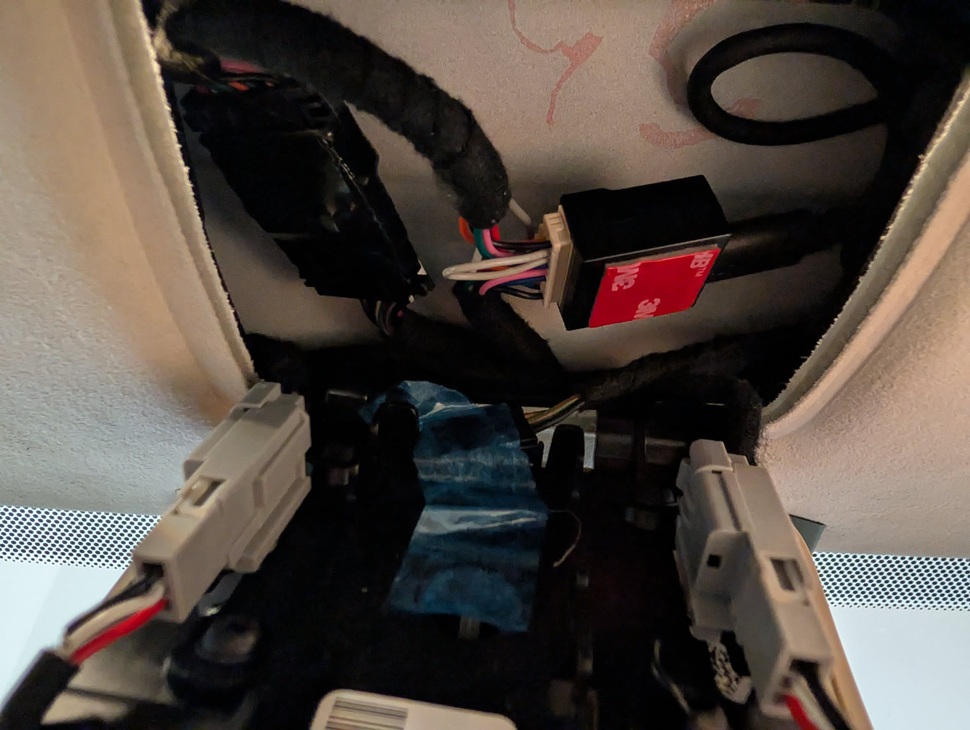
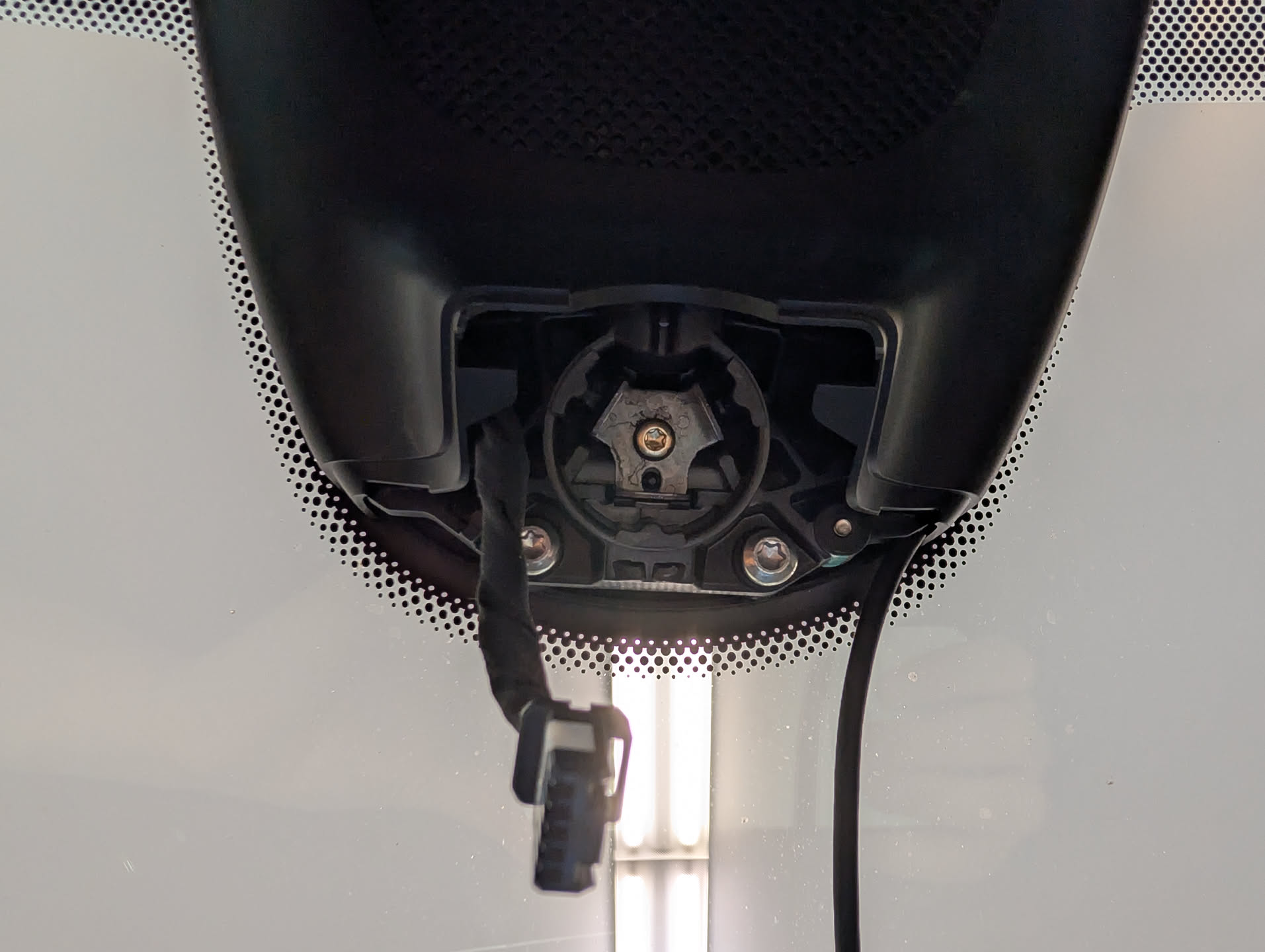
With the mirror assembly removed, unplug the connector to the mirror by pushing in both of the black sides of the connector and adding a pushing motion away to try and leverage the connector out. I found using two small flathead screwdrivers to push in the side tabs while trying to scoot the connector out worked the best. It’s tricky and can be frustrating, but you can get it!
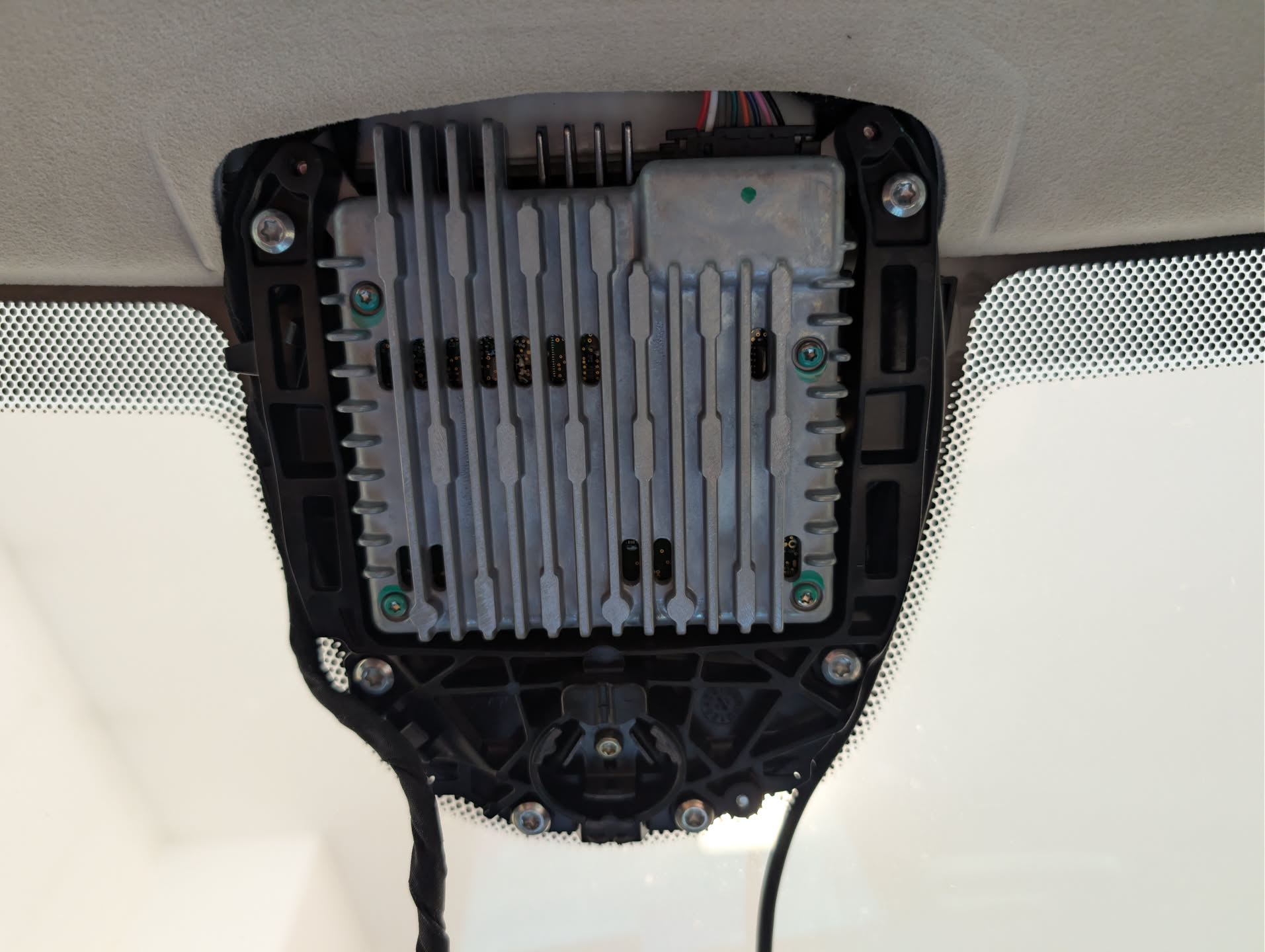
Remove the upper mirror headliner cover if you haven’t already. It’s held into place by two metal clips, pull straight down on the “back” side to detach it.
Pull the existing cable connected to the mirror assembly up through the headliner and route the one end of your harness back to the assembly and clip it into place (you should hear it click into place). Connect the other end of the harness to the cable that was previously connected to the mirror assembly. Then connect a USB-C cable to the developer harness box and route it down through the headliner.
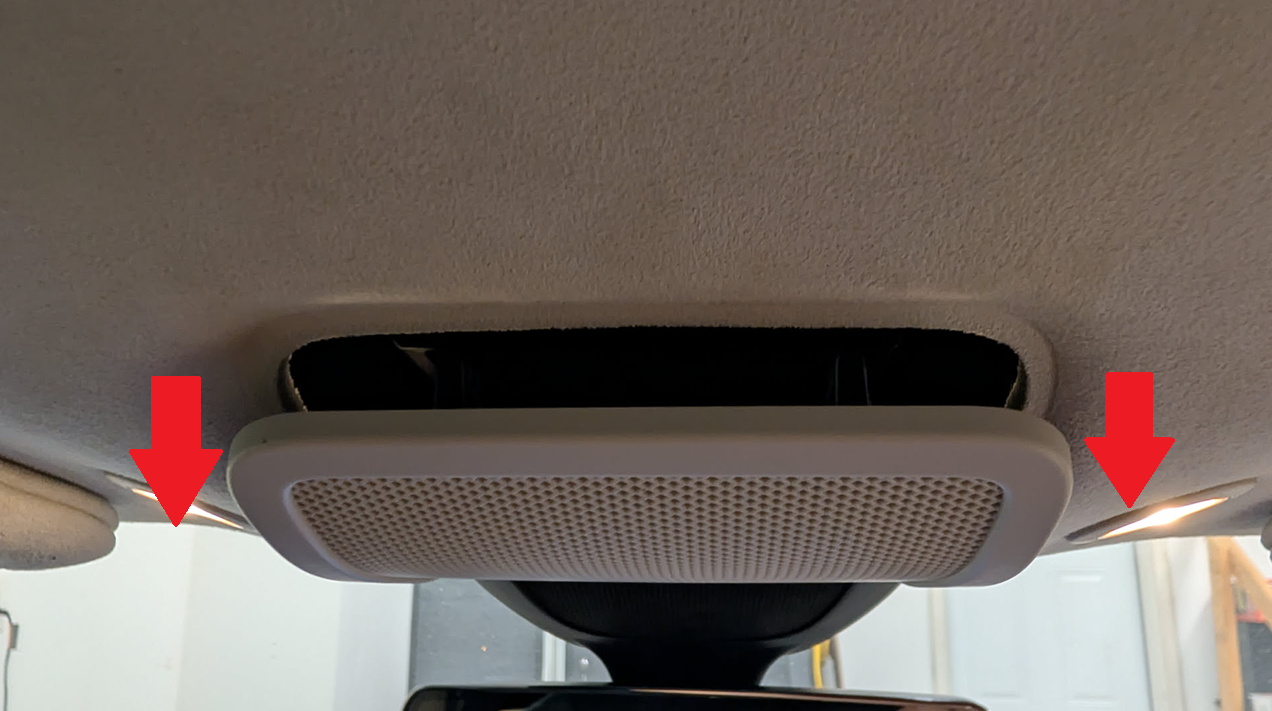
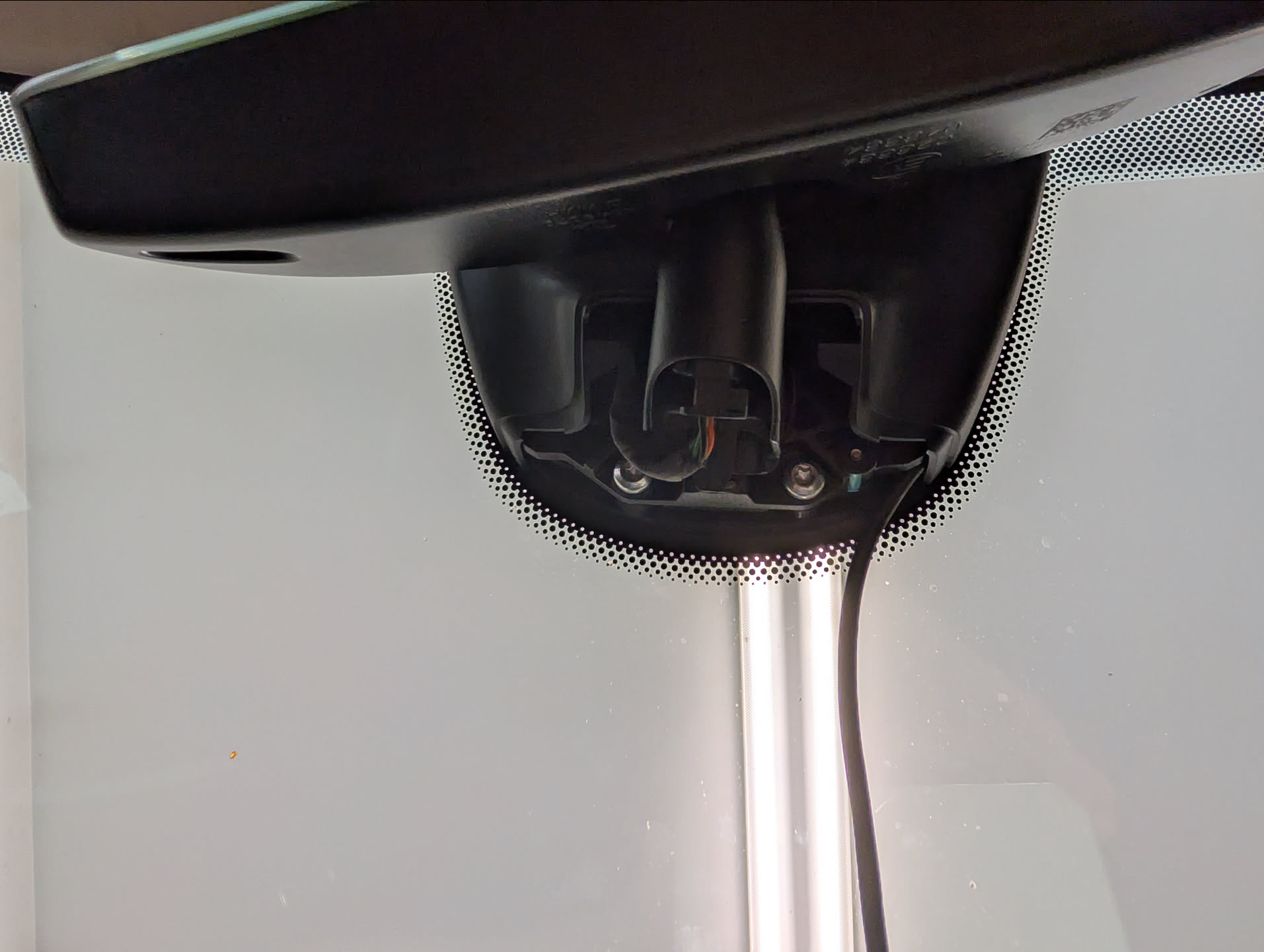
Looking up, I routed the USB-C cable from the Comma developer harness box around the mirror bracket and back into the headliner.
The top bracket should snap in place, even with the cable on the right side, with a tight fit.
Snap the mirror into place first and then connect the wiring harness to it. Make sure the mirror is fully snapped into place; it can feel like it has, even though it hasn’t.
Mount your Comma 4 on the mount and connect the USB-C cable from the dev harness to the comma and it should immediately start to power up.
Install the xnor fork for the Comma 4
When the Comma 4 boots, you’ll land on a setup screen. Connect to WiFi (this is not optional as you need connectivity for the next step).
Eventually, the Comma will prompt if you want to use openpilot or Custom Software. Stock openpilot won’t do anything for you here as it doesn’t support older Tesla vehicles with AP1, so select custom software.
The fork that keeps AP1 alive is xnor, maintained by xnor-tech (Lukas Loetkolben on GitHub). Docs on how to get started can be found here: https://wiki.xnor.shop/docs/general/installing_a_fork/ On this step,
Unrelated, whoever at Comma was responsible for the onboard keyboard on the Comma 4 should get a gold star. The second I saw the keyboard I got anxiety that it would be miserable to type the URL in, but the keyboard honestly functions incredibly well for such a small screen. Kudos!
The install should take about 5-10 mins; it’s pretty quick.
Notes:
The `xnor` branch is the precompiled one and it covers comma four + comma 3X for Tesla Model S/3/X/Y across HW1 through HW4 — HW1 being what we care about for AP1.
There’s also `xnor-dev` at `https://installer.comma.ai/xnor-tech/xnor-dev` which builds from source on the device. It takes considerably longer to install. Unless you have a reason to be on dev, take the precompiled branch.
Setup Comma 4
At this point, I ran through the rest of setup and calibration of the Comma 4.
Ideally, you mounted the Comma 4 so you can run through the driver detection mode and pass it on first try. After driver monitoring, you’ll be prompted to run through device calibration, where you drive the car > 15 mph for a little bit of time.
Unlike me, I mounted the Comma 4 blindly after tearing the mirror apart and one thing that later got me is the yaw of the device has to be within ±3.96°. Lucky me, I was off by 0.07 degrees at −4.03° and had to remount the whole thing. At time of writing this, Comma doesn’t have a mounting mode to show you want the yaw of the device is, so you kinda have best guess whether or not it’s level on the windshield. If it’s off, you’ll see a “Unable to calibrate” messages, with no details on what went wrong.
If you unfortunately have to tear the Comma 4 mounting bracket off, I used a large wide razor blade that you use when scraping items or cleaning windows. Strongly recommend using that or some sort of plastic prying tool as trying to pull it off with your fingers is pretty much impossible
Grab the Comma Connect app
Comma Connect is the interface which allows you to pull dashcam footage, live views of the camera, and drive details. I’ve developed a mobile app to try and simplify working with the comma device on the go. You can grab a free copy of the app on the Google Play store here: Comma Connect (Unofficial) – Apps on Google Play
In closing
At this point, everything should be working. If it is, go ahead and repeat the mirror disassembly steps in reverse to reassemble it.
This is a really brief guide and slightly scattered, but thought I’d post it as I couldn’t find what the mirror pins did and was curious if the original dev harness from Comma could be used as-is (which it looks like it can be! : )
Disclaimer: At time of writing this article (and likely still not today), I am not affiliated with, sponsored by, or have any investment in comma ai or openpilot. I’m just some random person that wants to make my car feel like a car of the future again.
Disclaimer 2: You are responsible for your own car and what you do with it. Follow local, state, and federal law when it comes to your vehicle and what you do with it.
Building My Own GPS Stratum-1 Time Server on a Raspberry Pi
Time silently hums away in the background, affecting everything we do today. Wake up, go to work, go to an appointment; all happen at specific times. Computers are no different, constantly logging time in logs, showing time in applications, and used for scheduling. In general, no one really cares about time because it’s typically “accurate enough” for most tasks. Most computers just automatically have the correct time and are accurate down to a second or so, with most people perfectly content that it’s technically approximately right. That being said, I’m neurotic and want nuclear-science-lab accuracy, knowing precisely what time it is.
While pool.ntp.org is a fantastic source of time, why settle when you can have sub-microsecond precision? No one is going to have a good time when you’re technically having a bad time.
For this project, I wanted to see how precise time can be in my house, owning it end to end — no leaning on someone else’s server out on the internet. In the industry, precision time is provided by what are called stratum-1 time servers and can sometimes be thousands of dollars. Given I’m cheap and don’t have a money tree, I decided to build my own stratum-1 time server in a relatively affordable way: a Raspberry Pi that pulls time straight off the GPS satellites overhead and serves it to everything on my LAN, no internet required.
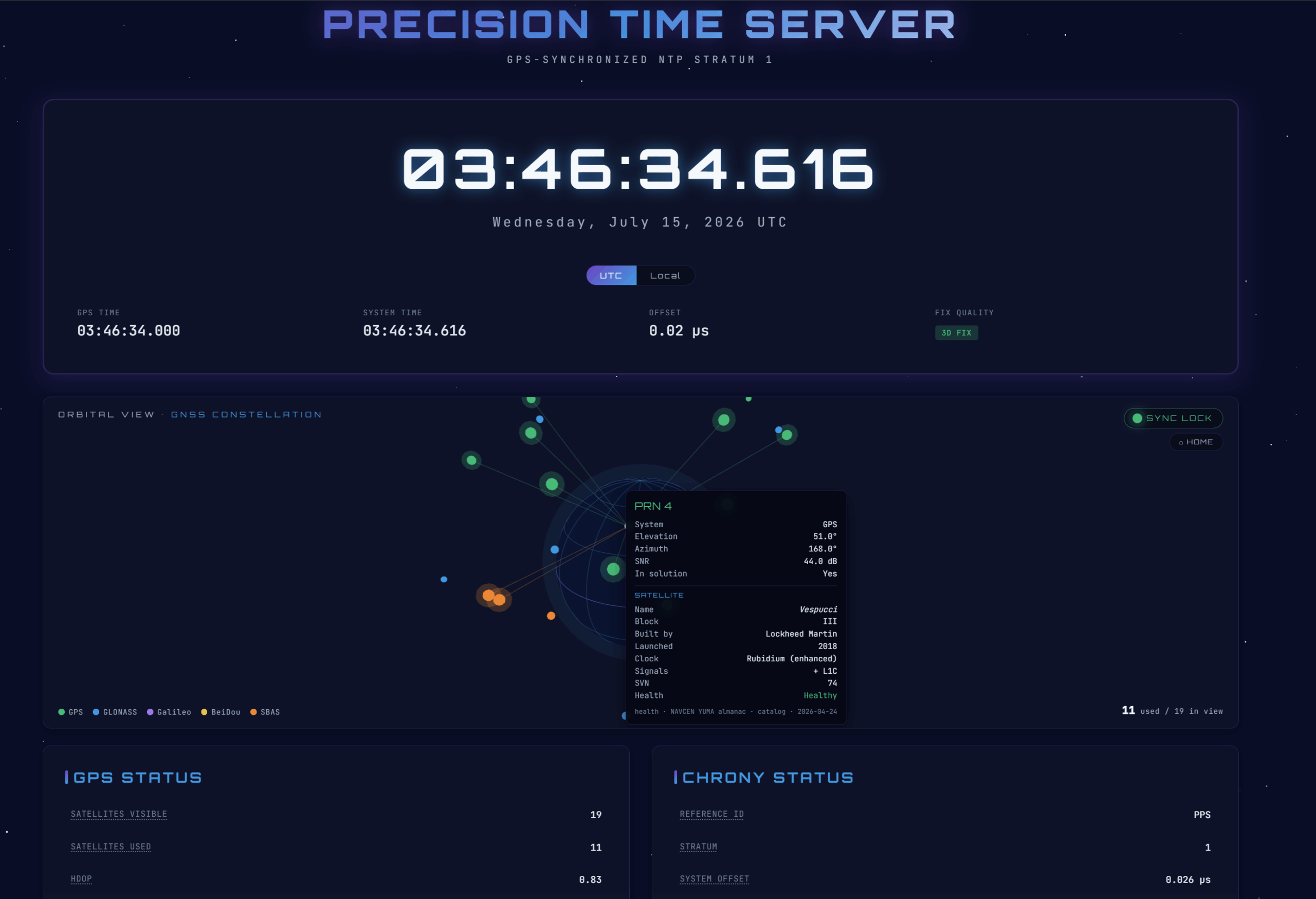
Along the way the project grew a second half, which is to visualize the satellite tracking and time sync. Once I had gpsd and chrony working, I wrote a small daemon that enables a live view of the calculated time, full gpsd + chrony stats, a satellite sky view, and an interactive 3D globe showing the GNSS constellation in space.
chrony instead of ntpd. chrony has native PPS support and a clean socket backend, so you skip the from-source NTP compile entirely.
Current Raspberry Pi OS paths. On Bookworm (and Trixie) the boot config lives at /boot/firmware/config.txt, not the old /boot/config.txt (which is now just a placeholder).
How it all fits together
Before wiring anything up, here’s a quick overview :
The timekeeping path — gpsd reads NMEA + PPS and feeds chrony; chrony disciplines the kernel clock and serves NTP to my network. This is what makes it a stratum-1 server. If you stop reading after Part 6, you’ve got a fully working time server.
The telemetry path — a small daemon written in Rust that reads the same gpsd data plus chrony’s stats and streams them to the dashboard over Server-Sent Events. It’s strictly read-only and has zero effect on timekeeping accuracy.
What you’ll need
Here’s the parts list I used:
Part
Notes
Raspberry Pi 3 or 4
Both work identically here. The Pi 4 has dedicated Gigabit Ethernet; on the Pi 3, Ethernet shares the USB bus, so keep other USB devices off it. The Pi 5 needs different UART steps and isn’t covered.
GPS HAT with PPS
I used the Uputronics Raspberry Pi GPS/RTC Expansion Board, and it’s what this guide is written against. PPS is mandatory for stratum-1; NMEA alone is only good to a few hundred milliseconds.
GPS antenna (active, timing-grade)
Amphenol PCTEL 3978D-HR-DH-W — the exact antenna I used: a weatherproof (IP67) GPS L1 dome antenna with a built-in LNA + filter (~40 dB gain) and a TNC-female connector. A real step up from a puck. Needs a clear-ish view of the sky.
Antenna mounting bracket
Amphenol PCTEL MMK1925 — the stainless-steel L-bracket for the WS397x-series dome (fits the 3978D). This and the antenna above are what I actually mounted.
Antenna coax
A run with the right ends for your antenna and HAT (see the note below). I didn’t spring for timing-grade coax — I used a cheap SMA extension cable like this one and it’s been perfectly fine.
All in all, the project cost ~$240 (inc. shipping, tax, etc). I didn’t include the cost of a raspberry pi since I had one unused from a prior project, but assuming you bought a new Pi; you are ~$360.
Notes before we get started
Check your HAT’s PPS pin. This guide assumes GPIO18 (the Uputronics default). Some HATs (e.g. Adafruit) use GPIO4. Adjust the gpiopin= value accordingly. Guess wrong and PPS will simply never show up.
Antenna connector & bias (if you’re using the dome antenna above). The 3978D outputs TNC female, while most GPS HATs (Uputronics included) use SMA — so plan a coax run with the right ends (TNC-male at the antenna, SMA-male at the HAT) or grab an adapter. It’s an active antenna (built-in LNA), so the HAT has to supply DC bias voltage on the coax; the Uputronics HATs do this, but confirm yours does. Being IP67 and bracket-mounted, it’s meant to live outdoors on a mast with a clear sky view.
You don’t have to mount it outdoors. The 3978D is a weatherproof, IP67, mast-mount dome. It’s built to bolt onto a roof and shrug off the weather. I didn’t put it on a roof. I bolted it to its MMK1925 bracket, set the whole thing up in my attic under asphalt shingles and 5/8″ OSB, and ran it back to the HAT with a cheap SMA extension cable instead of proper timing-grade coax. On paper that’s leaving signal on the table three different ways. In practice it’s been tracking ~16-20 satellites and holding a sub-microsecond lock the entire time. So: buy the better antenna over fancy cable if you are on a limited budget and don’t let “needs a clear view of the sky” scare you into a rooftop install (especially if you are HOA bound and limited to what you can mount outside). An attic on the sky-facing side of the house is likely going to do it for you.
Part 1 — The base OS
Flash Raspberry Pi OS Lite (64-bit) with Raspberry Pi Imager. In the Imager’s advanced settings (the gear icon), enable SSH and set the hostname (I’ll use timeserver for this guide) and locale before writing. Note: this Pi runs headless, which means you don’t have a monitor connected to it, so you want to be able to reach it on first boot.
A word on Bookworm vs Trixie. As of mid-2026 there are active reports of a Trixie serial regression where the GPIO UART stops receiving GPS data on hardware that worked fine on Bookworm (a suspected kernel/PL011 driver issue). For a device whose entire job is reliable time, Bookworm might be the safer choice today; but so far things have worked fine for me. The config paths and overlays are identical — but if NMEA never appears despite correct wiring, jump to the Trixie diagnostic in Troubleshooting. There’s also a Debian 12 vs 13 appendix at the bottom.
Here’s the first “gotcha” the Pi throws at you. The Pi 3/4 wire the good UART (PL011) to the onboard Bluetooth by default. We need that UART for the GPS, and we also need to stop Linux from using the serial port as a login console.
2a. Disable the serial login shell (but keep the hardware port)
sudo raspi-config
Under Interface Options → Serial Port:
login shell accessible over serial? → No
serial port hardware enabled? → Yes
Choose Finish but don’t reboot yet, we’ve got more config to add, and I’d rather reboot once.
2b. Disable Bluetooth to reclaim the UART
sudo vi /boot/firmware/config.txt
New to vi? Here’s the reader’s digest: press i to start typing (insert mode), make your edits, then hit Esc and type :wq followed by Enter to write and quit. If you fat-finger something and want to bail without saving, Esc then :q! throws your changes away. That’s genuinely 90% of what you need to survive vi.
Add this at the end (we’ll drop the PPS line in here too in Part 3, so it’s a single reboot):
# Reclaim the PL011 UART for GPS by disabling onboard Bluetooth
enable_uart=1
dtoverlay=disable-bt
Older guides use dtoverlay=pi3-disable-bt; the current canonical name is just disable-bt. raspi-config may have already added an enable_uart=1 line — a duplicate is harmless, but you can keep just one if it bugs you.
Then stop the Bluetooth-UART service:
sudo systemctl disable hciuart
On a Lite image (and commonly on Trixie) this may report Unit hciuart.service does not exist — and that’s totally fine. It ships with the pi-bluetooth package, which isn’t always installed, and disable-bt already turns Bluetooth off at the device-tree level. The overlay is what actually matters here; this step is just belt-and-suspenders.
Part 3 — Enabling PPS
PPS (pulse-per-second) is the secret sauce. NMEA sentences tell you what second it is; the PPS pulse tells you exactly when that second begins, down to the nanosecond. No PPS, no real stratum-1.
3a. Load the PPS-over-GPIO overlay
Still in /boot/firmware/config.txt, add (adjust gpiopin for your HAT):
# Pulse-Per-Second input on GPIO18
dtoverlay=pps-gpio,gpiopin=18
Then load the kernel module at boot and reboot so both the UART and PPS changes take effect:
echo 'pps-gpio' | sudo tee -a /etc/modules
sudo reboot
3b. Verify raw GPS and PPS
First confirm the UART is on the GPIO header, then read raw NMEA:
Always use /dev/serial0 — it’s a symlink that always points to whichever UART is on the GPIO header, so you don’t have to care whether it’s ttyAMA0 or ttyS0 today. Ctrl-C to stop.
If you see garbled characters instead of clean $GNRMC/$GNGGA lines, don’t panic, that’s a baud-rate mismatch, not a fault. Bytes are flowing; the port’s just reading them at the wrong speed. Set the rate explicitly and re-read until it’s clean:
sudo stty -F /dev/serial0 9600 raw   && sudo cat /dev/serial0   # common u-blox default
sudo stty -F /dev/serial0 38400 raw  && sudo cat /dev/serial0
sudo stty -F /dev/serial0 115200 raw && sudo cat /dev/serial0   # mine with the Uputronics unit
Write down the rate that produces readable NMEA, you’ll need it for gpsd in Part 4. It’s a property of your GPS module, not the OS. Many u-blox modules use 9600, but others (including some Uputronics units) run at 115200. Mine was 115200.
Now confirm the pulse itself. This needs a satellite fix; most HATs blink a timepulse LED once they’ve locked:
No output usually just means no fix yet, wait a couple mins or try moving the antenna to a different location. If you are running the antenna in a faraday cage, expect no results since it won’t find a satellite.
Part 4 — gpsd
sudo apt install -y gpsd gpsd-clients
sudo vi /etc/default/gpsd
Point it at your HAT (using the baud rate you found in Part 3b):
-n polls the GPS immediately at boot; -s 115200 pins the serial speed so gpsd doesn’t autobaud its way into garbage. Enable and check:
sudo systemctl enable --now gpsd
sudo systemctl restart gpsd      # ensure it picks up the new config
gpsmon        # or: cgps -s
gpsmon shows the raw feed (fast-scrolling UBX packets are normal and healthy); cgps -s gives a calmer table. You want a 3D fix, satellites with good SNR, low DOP values, and a PPS line with a near-zero offset. That PPS line is the confirmation I was chasing.
Tip: gpsd takes exclusive control of the port. If you want to cat /dev/serial0 again for debugging, stop gpsd first: sudo systemctl stop gpsd gpsd.socket.
Part 5 — chrony with the socket backend
sudo apt install -y chrony
Here’s the key design point, and the reason chrony is such an upgrade over the old ntpd dance: gpsd hands the precise PPS timestamp to chrony through a Unix socket (chrony’s SOCK refclock). gpsd automatically writes to /run/chrony.<device>.sock once chrony has created it — neatly sidestepping the classic headache where chrony drops privileges and can no longer read /dev/pps0 directly.
sudo vi /etc/chrony/chrony.conf
Add this at the end:
# --- GPS + PPS reference clocks -------------------------------------------

# Coarse absolute time from gpsd (NMEA) via shared memory.
# 'noselect' = never sets the clock, only gives the PPS pulse a whole-second
# label. Tune 'offset' after calibration (Part 7d) if PPS won't lock.
refclock SHM 0 refid GPS precision 1e-1 offset 0.0 delay 0.2 noselect

# Precise PPS via gpsd's socket. gpsd writes here automatically.
# 'lock GPS' anchors each pulse to the GPS second above.
refclock SOCK /run/chrony.pps0.sock refid PPS lock GPS prefer

# Serve time to your LAN (adjust to your subnet) and keep serving during
# brief GPS dropouts.
allow 192.168.0.0/24
local stratum 1

# Optional internet fallback if the antenna fails. Remove for air-gapped use.
pool 2.debian.pool.ntp.org iburst
Restart both, in order — chrony first, so its socket exists by the time gpsd starts:
Confirm the socket exists (it should be owned by root and actually be a socket — note the leading s in the permissions):
ls -l /run/chrony.*.sock # expect /run/chrony.pps0.sock
Part 6 — Confirming you’ve actually got a stratum-1 server
Give it 5 minutes to settle, then watch the sources roll in:
watch -n 2 chronyc sources -v
You’re looking for #* next to PPS. The asterisk means it’s the selected source disciplining the clock. It starts at #? (not enough samples yet), climbs its reachability register (0 → 1 → 3 → 7 → 17 → 37 → 77 → 377), then finally promotes to #*. The internet servers drop to ^- (background sanity checks) once PPS takes over. Watching that register tick up is weirdly satisfying:
Look for Stratum : 1, Reference ID … (PPS), and a System time offset down in the sub-microsecond range. That, right there, is a working stratum-1 time server. I may have taken a screenshot.
Reading the numbers:System time / Last offset are your current accuracy (nanoseconds-to-microseconds once locked). RMS offset looks alarming at first (hundreds of µs) because it’s a rolling average still dominated by the noisy warm-up; it falls steadily the longer it runs, so don’t judge it too early. Root delay near zero and Reference ID = PPS confirm a direct hardware lock.
The falseticker trap. chrony will reject PPS if the GPS (NMEA) label is more than ±200 ms off the true second. If PPS stays stuck at #?, that’s almost always the culprit, calibrate the offset (Part 7d).
At this point the time server itself is done. Below is the fun part of visualizing the setup. If you just wanted accurate time, congratulations, you can stop here.
Part 7 — The telemetry daemon
Now to create a live dashboard to visualize everything. The daemon does four things:
Connects to gpsd’s JSON socket on 127.0.0.1:2947 — the same protocol libgps speaks, so I get identical data without any C FFI.
Polls chrony once a second with chronyc -c tracking (the -c flag hands back machine-readable CSV from chrony’s command socket).
Merges both, streams them to the browser over SSE at /data, and serves the dashboard.
(Optional, off by default) fetches and caches the NAVCEN GPS almanac and serves it at /satinfo for satellite-health enrichment (more in Part 8).
sudo apt install -y git
git clone https://github.com/JackStromberg/gps-timeserver-daemon.git
cd gps-timeserver-daemon
ls -al
You should end up with:
gps-timeserver-daemon/
├── Cargo.toml
├── src/main.rs
└── static/index.html      # already set to live mode (USE_SIMULATION = false)
7a. Install Rust and build
curl --proto '=https' --tlsv1.2 -sSf https://sh.rustup.rs | sh   # press Enter for defaults
source "$HOME/.cargo/env"
cargo --version                                                  # should print a version
sudo apt install -y build-essential                              # C linker (Lite images lack it)
cd gps-timeserver-daemon
cargo build --release
cargo: command not found right after installing? The installer can’t modify an already-running shell’s PATH. Run source "$HOME/.cargo/env" (or just open a new terminal). If ls ~/.cargo/bin/cargo doesn’t exist, the install didn’t finish — re-run the curl … | sh line.
error: linker 'cc' not found? Install build-essential (above) and rebuild.
Fair warning: the first build on a Pi is slow. It compiles tokio, axum, reqwest, and the whole rustls TLS stack from scratch (several minutes), and it may look completely frozen at the final link step. That’s normal. Subsequent builds are incremental and quick.
7b. Run it
./target/release/gps-timeserver-daemon
It prints its listen address and stays running (it’s serving, so it won’t hand you back a prompt). Open http://<pi-ip>:8080 from a browser on your LAN and you should see the dashboard light up.
The port is configurable — see Part 8. If 8080 is already taken (a Docker service, say), you’ll get AddrInUse; set a different PORT rather than editing code.
7c. The /data contract
The daemon emits one JSON object per second in this shape (the dashboard reads exactly these field names):
Telemetry::to_json() in src/main.rs is the single source of truth for this contract — if you want to add a field, that’s the one place to touch.
7d. Calibrating the GPS offset (optional)
If PPS refuses to lock, let it run ~15 minutes, then read the measured GPS offset:
chronyc sourcestats
Take the GPS source’s Offset (say +512ms), convert to seconds, and set it as offset on the SHM 0 line in chrony.conf (e.g. offset 0.512). Restart chrony. This nudges the NMEA label back inside the ±200 ms window so PPS gets accepted — the fix for that falseticker trap I mentioned above.
Part 8 — Configuration via environment variables
I wanted to be able to change behavior without recompiling, so the daemon reads a handful of environment variables at startup. Set them when running manually, or via Environment= lines in the systemd unit (Part 9).
Variable
Default
Purpose
PORT
8080
Port to bind (binds 0.0.0.0:PORT).
LISTEN_ADDR
(unset)
Full host:port; overrides PORT. Use 127.0.0.1:8088 to serve only locally, 0.0.0.0:8088 for the LAN.
SATINFO_ENABLED
(off)
1/true/yes/on enables the optional NAVCEN satellite-info fetcher. Off means the daemon makes zero outbound network calls — safe for air-gapped setups.
SATINFO_INTERVAL_HOURS
168 (weekly)
How often to refresh the NAVCEN data. The constellation changes only a few times a year, so weekly (or 720 ≈ monthly) is plenty.
SATINFO_URL
NAVCEN YUMA almanac
Override the source if needed.
The optional satellite-info fetcher
When SATINFO_ENABLED=1, a background task fetches the NAVCEN GPS almanac (US Coast Guard, public-domain US-government data), caches it in memory, and serves it at /satinfo. The dashboard uses it to add live health status to each GPS satellite’s hover tooltip. On failure it retries in an hour; on success it waits the full interval. Left disabled (the default), /satinfo returns {"enabled": false} and the dashboard silently falls back to its built-in reference table — so nothing breaks either way.
Quick checks once you’ve enabled it:
journalctl -u timeserver-dashboard -n 20 --no-pager   # look for: satinfo: fetched N satellites
curl -s localhost:8080/satinfo | head -c 300          # expect "enabled":true and a satellites object
On data sources & licensing (not legal advice): NAVCEN is public-domain US-government data — no account, redistribution-safe. The dashboard’s built-in reference table is assembled from public GPS records. If you instead point live mode at CelesTrak, respect their access etiquette (cache; don’t poll more than roughly every 2 hours) and cite them. There’s a fuller Licensing appendix at the bottom.
Part 9 — Running it at boot
I want this thing to just come back on its own after a power blip, so let’s give it a systemd unit:
sudo vi /etc/systemd/system/timeserver-dashboard.service
[Unit]
Description=GPS Timeserver Dashboard
After=network-online.target gpsd.service chrony.service
Wants=network-online.target
[Service]
# Adjust User and paths to where you put the project.
User=pi
WorkingDirectory=/home/pi/gps-timeserver-daemon
ExecStart=/home/pi/gps-timeserver-daemon/target/release/gps-timeserver-daemon
Restart=on-failure
RestartSec=3
# Optional configuration (see Part 8):
Environment=PORT=8088
# Environment=SATINFO_ENABLED=1# Environment=SATINFO_INTERVAL_HOURS=168
[Install]
WantedBy=multi-user.target
WorkingDirectory matters more than it looks. The daemon serves static/index.html relative to where it runs, and systemd does not inherit your shell’s current directory. Point this at the wrong place and you’ll get a 404 for the dashboard.
Enable and verify:
sudo systemctl daemon-reload
sudo systemctl enable --now timeserver-dashboard
systemctl status timeserver-dashboard          # expect: active (running)
journalctl -u timeserver-dashboard -n 5 --no-pager   # confirm the listen address
Whenever you edit the unit file (say, to change an Environment= line), run sudo systemctl daemon-reloadand thensudo systemctl restart timeserver-dashboard. Skipping the reload is the classic “my change didn’t take” gotcha. systemctl show timeserver-dashboard -p Environment prints what systemd is actually passing, which is handy when you’re sure you fixed it but it disagrees.
One nice quality-of-life note: editing only static/index.html (HTML/CSS/JS) needs no rebuild and no restart — the daemon serves it from disk at request time. Just hard-refresh the browser (Ctrl-Shift-R). Only changes to src/main.rs or Cargo.toml require cargo build --release.
Part 10 — Serving time to the rest of the network
Everything so far only disciplines the Pi’s own clock. To let other machines sync from it, chrony has to answer NTP requests — and it refuses by default, which is a good safety default but not what we want here.
10a. Match the allow line to your LAN
hostname -I # your Pi's IP, e.g. 192.168.1.50
If the Pi is 192.168.1.50, your subnet is likely 192.168.1.0/24. Edit chrony.conf so the allow line matches — a whole subnet (allow 192.168.1.0/24), a single host (allow 192.168.1.100), or allow all only if you deliberately mean to serve the public — then restart:
sudo systemctl restart chrony
10b. Confirm it’s serving
sudo ss -ulnp 'sport = :123'    # something should be bound to UDP 123
chronyc clients                 # machines that have requested time (empty until clients connect)
If you run a firewall on the same Raspberry Pi (ufw, nftables, or Docker-managed iptables), open NTP: sudo ufw allow 123/udp. A plain Lite install has no firewall and needs nothing.
10c. Point your clients at the Pi
Your Pi is stratum 1, so anything syncing to it becomes stratum 2 — perfect for a LAN. Here’s how I pointed a few common clients at it:
Router: set its NTP server to the Pi’s IP — this pushes time locally to every device automatically, using it as an ntp source.
Linux: add server <pi-ip> iburst to /etc/chrony/chrony.conf, restart chrony.
Windows:w32tm /config /manualpeerlist:"<pi-ip>" /syncfromflags:manual /update then w32tm /resync.
macOS: System Settings → General → Date & Time, or sudo sntp -sS <pi-ip>.
Verify from a client with chronyc -h <pi-ip> tracking, sntp <pi-ip>, or ntpdate -q <pi-ip>. Back on the Pi, chronyc clients will list everyone pulling time from you.
Part 11 — Actually using the dashboard
Open http://<pi-ip>:<port> (default 8080, or 8088 in my examples above). Everything updates once per second from the live feed.
Time header. A large clock with millisecond precision, plus GPS time, system time, and the chrony offset. The UTC / Local toggle under the clock switches every time on the page between UTC and your browser’s local zone, and it remembers your choice across reloads.
Orbital globe (the hero panel, and my favorite). A holographic Earth with each GNSS satellite placed in true 3D from its azimuth/elevation, color-coded by constellation, with beams running from the satellites in use down to a marker at your location.
Drag to rotate (mouse or touch): horizontal spins around the poles, vertical tilts.
Home button (top-right) or double-click the globe to glide back to the default view.
Hover a satellite for its details: PRN, constellation, elevation, azimuth, SNR, and whether it’s in the solution — plus, for GPS, catalog facts (block, manufacturer, clock type, launch year, name, SVN) and, if /satinfo is enabled, live health.
Hover a legend entry (GPS/GLONASS/Galileo/BeiDou/SBAS) for a one-line explanation of that constellation.
Status panels. GPS Status, Chrony Status, Position & Navigation, and System Info. Hover any metric label (they’ve got a dotted underline) for an explanation of what it means and what a good value looks like — HDOP, TDOP, EPX/EPY/EPV, the chrony offsets, and so on. I added these mostly so I’d stop having to look them up myself.
Sky view + satellite table. Polar az/el plot, plus a detailed per-satellite table.
Satellite-info modes (dashboard side)
Near the top of the <script> in static/index.html:
SATINFO_MODE — 'daemon' (default; asks this server’s /satinfo, no CORS, falls back to the built-in table if the server has fetching disabled), 'offline' (built-in table only, never fetches), 'celestrak' (fetch CelesTrak directly from the browser; may hit CORS), or 'off'.
The built-in table always supplies block/manufacturer/clock/name/launch; /satinfo adds live health on top.
Previewing with simulated data
static/index.html ships with const USE_SIMULATION = false; (live). To preview the UI without any hardware — say you’re building this on your laptop before the HAT arrives — open a copy with it set to true. It generates fake data (a fixed location, invented satellites, a locked stratum-1 state) so every visual works offline.
Heads up: the globe and all hover tooltips are mouse-based, so the hover interactions won’t appear on touchscreens (dragging the globe still works via touch).
Part 12 — Optional: running the dashboard in Docker
You can containerize the dashboard daemon — but keep gpsd + chrony on the host. The kernel clock is a single host-wide resource; putting chrony in a container means granting it SYS_TIME and steering the host clock across the container boundary — extra layers wrapped around your most timing-sensitive component. The daemon, on the other hand, is a read-only consumer and containerizes cleanly with zero precision impact.
Here’s an example multi-stage Dockerfile:
# Build
FROM rust:1-bookworm AS build
WORKDIR /app
COPY Cargo.toml Cargo.lock* ./
COPY src ./src
RUN cargo build --release

# Runtime
FROM debian:bookworm-slim
RUN apt-get update && apt-get install -y --no-install-recommends \
      chrony ca-certificates && rm -rf /var/lib/apt/lists/*
WORKDIR /app
COPY --from=build /app/target/release/gps-timeserver-daemon /usr/local/bin/
COPY static ./static
CMD ["gps-timeserver-daemon"]
Note that chrony is installed here only for its chronyc client (the daemon shells out to it) — the container does not run a chrony daemon. Run it sharing the host network and chrony’s command socket:
--network host lets the daemon reach host gpsd at 127.0.0.1:2947 and keeps PORT/LISTEN_ADDR working normally.
Mounting /run/chrony gives the container’s chronyc access to chrony’s command socket.
You do not need --device=/dev/serial0 or /dev/pps0 here — the daemon never touches the hardware directly; it reads gpsd and chronyc. (Those devices only matter if you were containerizing gpsd/chrony too, which, again, I’d steer you away from.)
Troubleshooting
Here’s a running list of things I’ve stumbled across:
Symptom
Likely cause / fix
cat /dev/serial0 shows nothing
UART not freed. Confirm dtoverlay=disable-bt is in /boot/firmware/config.txt (not /boot/), hciuart disabled, rebooted. Check ls -l /dev/serial0 points to ttyAMA0.
cat /dev/serial0 shows garbled text
Baud-rate mismatch (not a fault). Set the rate with stty -F /dev/serial0 <rate> raw and re-read; use the working rate in gpsd’s -s.
Silent serial on Trixie only, same HW worked on Bookworm
Suspected Trixie UART/PL011 regression. Diagnose: pinctrl poll 14-15 &, then trigger GPS data — if GPIO15 (RX) never changes level, no bytes are reaching the pin (a kernel issue, not your config). Try linux-modules-extra-raspi, pin an older kernel, or fall back to Bookworm.
ppstest prints nothing
No fix yet, or wrong PPS pin. Give it sky view; verify gpiopin= (4 vs 18).
chrony PPS stuck at #?
GPS/NMEA offset > 200 ms → falseticker. Calibrate the SHM 0 offset (Part 7d); make sure /dev/pps0 is in gpsd DEVICES and /run/chrony.pps0.sock exists.
Dashboard “Waiting for data…”
Daemon can’t reach gpsd. Check systemctl status timeserver-dashboard and that gpsd is up on :2947.
Dashboard returns 404
WorkingDirectory in the unit doesn’t point at the project root, so static/index.html isn’t found. Fix the path, daemon-reload, restart.
Daemon exits with AddrInUse
The port’s taken (e.g. Docker on 8080). Set Environment=PORT=8088 (or another free port); sudo ss -ltnp 'sport = :8080' shows the culprit.
/satinfo shows enabled:false
SATINFO_ENABLED not set/true, or daemon-reload skipped after editing the unit. systemctl show … -p Environment to verify.
/satinfoenabled:true but count:0
NAVCEN fetch/parse failed (check the error field and the journal). Network blip → it retries within an hour; persistent → check outbound HTTPS.
cargo: command not found
PATH not loaded: source "$HOME/.cargo/env". If ~/.cargo/bin/cargo is missing, re-run the rustup installer.
cargo build → linker 'cc' not found
sudo apt install -y build-essential, then rebuild.
Clients can’t sync
The allow subnet in chrony.conf has to match your LAN; open UDP/123 if you run a firewall.
Satellites look frozen on the globe
Expected! GPS is MEO (~2 orbits/day) and moves only gradually in az/el; the receiver also updates angles slowly. Check back in 20–30 min and the pattern will have shifted.
What you end up with
So where does all this leave you? Two things:
A stratum-1 NTP server disciplined by GPS + PPS, accurate to the microsecond or better, serving your whole LAN with no internet dependency. Every device on my network now sets its clock from a little box in my attic pulling time straight out of the sky, and I find that quietly delightful.
A live dashboard showing the calculated time, full gpsd + chrony stats with hover explanations, an interactive 3D constellation globe with per-satellite detail, and a sky view — all fed by the same hardware over SSE, with a clean JSON contract you can extend however you like.
If you want to keep tinkering, there are really just two files worth revisiting: src/main.rs (where Telemetry::to_json() defines the data contract) and static/index.html (METRIC_HELP, GPS_SAT_DB, and the render functions). Everything I’d want to customize lives in one of those two places.
If you made it this far, congrats on your new clock! Your clock is now more accurate than it has any reason to be!
Appendix A — Debian 12 (Bookworm) vs Debian 13 (Trixie)
Both work; most steps are identical. I verified everything on Debian 12 & 13 exactly as written above.
Topic
Debian 12 / Bookworm
Debian 13 / Trixie
Boot config path
/boot/firmware/config.txt
Same
disable-bt / pps-gpio overlays
Same
Same
Serial device
/dev/serial0 → ttyAMA0 (always prefer serial0)
Same
systemctl disable hciuart
Usually succeeds
Often Unit … does not exist — harmless
GPIO UART receiving GPS
Reliable
Regression risk (mid-2026): no RX bytes despite correct config. Diagnose with pinctrl poll 14-15; may need linux-modules-extra-raspi, an older kernel, or Bookworm
gpsd / chrony
Stock; config as written
Newer; same config syntax, chronyc -c tracking CSV unchanged
Recommendation
Preferred for a time server
Works, but verify the serial link early
Remember: serial baud rate is a property of your GPS module, not the OS — it’s handled identically on both.
Appendix B — Environment variables (quick reference)
Daemon (systemd Environment= or shell):
Variable
Default
Notes
PORT
8080
Bind port.
LISTEN_ADDR
(unset)
Full host:port; overrides PORT.
SATINFO_ENABLED
off
1/true/yes/on to enable NAVCEN fetch. Off = no outbound calls.
SATINFO_INTERVAL_HOURS
168
Refresh cadence (weekly).
SATINFO_URL
NAVCEN YUMA
Source override.
Dashboard (static/index.html constants):
Constant
Default
Notes
USE_SIMULATION
false
true = fake data for previewing.
SATINFO_MODE
'daemon'
daemon / offline / celestrak / off.
Appendix C — Licensing & data sources
Not legal advice. For personal, non-commercial use you’re clear on all of the below.
GPS orbital/almanac data is US-government, public-domain. NAVCEN (US Coast Guard) serves it with no account and is redistribution-safe — the recommended live source here.
CelesTrak (an alternative live source) redistributes the same government data and adds convenient PRN/block labeling. Respect their access etiquette: cache results and don’t poll more than roughly once every two hours; cite CelesTrak; note that it isn’t an official source. Commercial redistribution is a “contact them first” situation.
The dashboard’s built-in reference table is factual data (which PRN, block, launch year, manufacturer) assembled from public records; facts aren’t copyrightable.
For anything commercial or internet-facing at scale using, review each source’s current terms directly.