Category Archives: Networking

Networking Stuff!

Configuring DHCP Failover for Server 2012 R2

In this tutorial, we will implement one of Server 2012's newest features, DHCP Failover.  Before Server 2012, DHCP failover was achieved through Windows Failover Cluster. Now, Server 2012 has native tools built into the DHCP role to support failover without the need to setup clustering services.  It is nice to note that DHCP failover is fully supported in all server editions of Windows Server 2012 (Foundation, Standard, Data Center), allowing everyone to provide this role in high availability.

Before beginning, this tutorial assumes the following prerequisites to this tutorial:

  • Two Server 2012 servers have been installed and joined to your domain as member servers
  • Both servers have installed the DHCP role
  • One of the servers has been configured with your desired DHCP scopes
  1. Login to your primary DHCP server that has been configured with the DHCP scopes
  2. Open up the DHCP program
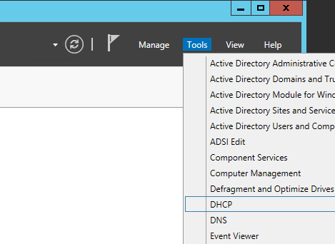
    1. Launch Server Manager
      Server 2012 R2 - Server Manager
    2. Click Tools->DHCP
      Server Manager - Tools - DHCP
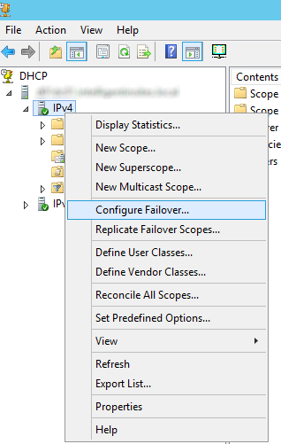
    3. Expand your DHCP server and right click on IPv4 and select Configure Failover...
      DHCP - IPv4 - Configure Failover
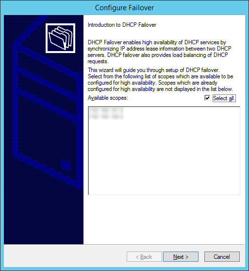
    4. On the Introduction to DHCP Failover page, click Next to allow failover of all DHCP scopes.
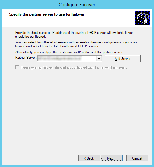
      Optionally, uncheck Select all and select the specific scopes you would like to allow to failover and then click Next.
      Configure Failover - Introduction to DHCP Failover
    5. Click on the Add Server button
      Configure Failover - Specify the partner server to use for failover - Add Server
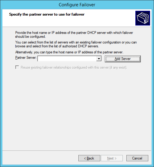
    6. Check This authorized DHCP server, select the server you would like to use to allow failover, and then click OK
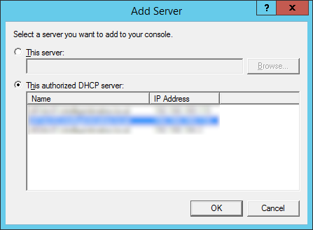
      Configure Failover - Specify the partner server to use for failover - Add Server - Authorized DHCP server
    7. Click Next
      Configure Failover - Specify the partner server to use for failover - Partner Server
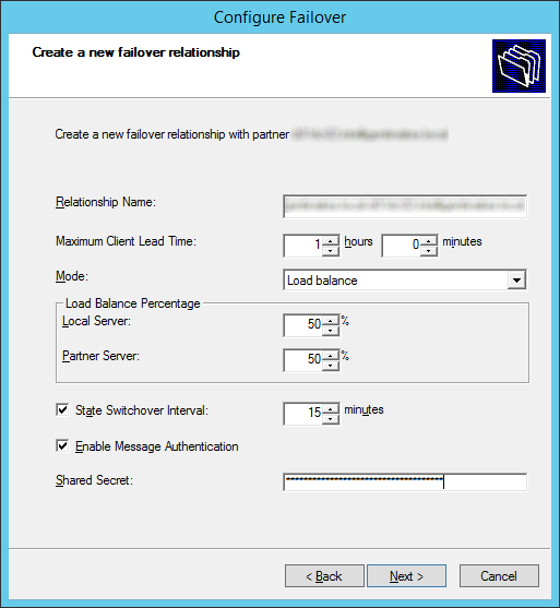
    8. Enter in the settings you wish to use and then click Next.  I would recommend entering a Shared Secret and checking the State Switchover Interval to failover in the event a server fails unexpectedly.
      Notes:
      If you are failing over to another DHCP server on the same subnet, it is recommended to setup loadbalancing.  If you are failing over your DHCP server to another network, set the mode to Hot standby.  Additionally, here is a list with more indepth details on what each option does.

      • Relationship Name: Descriptive name to describe this DHCP Failover relationship.  This can be named anything to help you understand the server relationship.
      • Maximum Client Lead Time: Specifies the amount of time for which a DHCP lease may be renewed by either failover peer without contacting the other.  It also specifies the amount of time that either DHCP server will wait in a “partner down” state before assuming control of the entire IP address range within the scope.  ( default = 1 hour ).
      • Mode: Select Load Balance ( default – Active / Active ) or Hot Standby ( Active / Passive )
      • Load Balance Percentage: Specifies the percentage of the IP Address range to reserve for each server in the failover relationship.  Each server will use their assigned range of addresses prior to assuming control over the entire IP Address range of a scope when the other server transitions into a “partner down” state and the Maximum Client Lead Time ( specified above ) passes.
      • Auto State Switchover Interval: When selected, specifies the amount of time that elapses before a DHCP Server is automatically transitioned to a “partner down” state when network communication is interrupted to a DHCP Server.  If this option is unchecked, an administrator must manually transition the status of a DHCP Server into a “partner down” state using the DHCP Management console or PowerShell. ( when checked, the default = 60 minutes )
      • Enable Message Authentication: check this checkbox option to enable authentication of failover replication traffic between servers
      • Shared Secret:  Type a “Shared Secret” ( ie., a Password ) to be used to authenticate the failover connection between servers
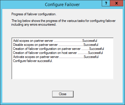
      Configure Failover - Create a new failover relationship

    9. Click Finish
      Configure Failover - Summary
    10. Click Close on the results dialog, confirming the failover configuration was properly setup.
      Configure Failover - Progress of failover configuration
    11. Optionally, you can login to your secondary DHCP server to confirm failover has successfully been setup.
      1. On the secondary DHCP server, right click on one of your DHCP scopes and select Properties
        DHCP - IPv4 - Scope - Properties
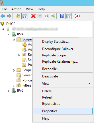
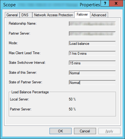
      2. Select the Failover tab and you should see your failover settings in effect.
        DHCP - Scope Properties

That's all that's to it!  Hurray for high availability! 🙂

Notes:

Descriptions of each of the failover options were found on the following technet article: http://blogs.technet.com/b/keithmayer/archive/2012/10/28/step-by-step-scoping-out-the-new-dhcp-failover-in-windows-server-2012-31-days-of-favorite-features-part-28-of-31.aspx

An offial Microsoft KB article on configuring DHCP failover can be found here: http://technet.microsoft.com/en-us/library/hh831385.aspx

Migrate DHCP Role from Server 2008 R2 to Server 2012 R2

After doing a quick google search, it appears you can easily migrate your DHCP server as long as you have both your current DHCP server (running Server 2008 R2) and a new Windows Server 2012 server you are going to designate as a DHCP server.

  1. Login to your new Server 2012 R2 machine with the DHCP role installed
  2. Open up a Powershell shell
    Server 2012 - Powershell
  3. Execute the following command to export the configuration from the Server 2008 R2 DHCP Server
    1. Export-DhcpServer –ComputerName win2k8r2-dhcp.corp.contoso.com -Leases -File c:\users\yourusername\Desktop\dhcpexp.xml -verbose
      Export-DhcpServer Server 2012
  4. Execute the following command to import the configuration into your new Server 2012 R2 DHCP Server; must be an Administrator running this PowerShell command.
    1. Import-DhcpServer –ComputerName win2k12r2.corp.contoso.com -Leases –File C:\users\yourusername\Desktop\dhcpexp.xml -BackupPath C:\users\yourusername\Desktop\backup\ -Verbose

Notes: Credit goes to the following technet article for the powershell commands and a more in-depth explanation: http://blogs.technet.com/b/teamdhcp/archive/2012/09/11/migrating-existing-dhcp-server-deployment-to-windows-server-2012-dhcp-failover.aspx

Dell PowerConnect 5548 - Enable port mirroring/monitoring via command line

To enable port mirror/monitoring on the Dell PowerConnect 5548 series switches, please follow the following steps:

  1. SSH or Telnet to the switch
  2. Login to the switch
  3. Execute the command: enable
  4. Execute the command: config
  5. Execute the command: interface gigabitethernet 1/0/##
    1. In this case, use the port number of the device that will be getting the traffic to analyze.  This is the interface your "wireshark" machine would be connected to, to do a packet capture.
  6. Execute the command: port monitor gigabitethernet 1/0/##
    1. In this case, use the port number of the device you want to see the network traffic/activity on.  For example, if my device that I wanted to monitor was on gigabit port 1/0/5, I would use that, not the machine that is going to receive the traffic (not your "wireshark" machine).

Once you are done with the forward, you can disable port monitoring/mirror by executing the following command after running through steps 1-5 again: no port monitor gigabitethernet 1/0/##

Last, if you want to see the status of your mirrored/monitored port, you can do so by executing the following command after repeating steps 1-3: show ports monitor

Tutorial: 802.1X Authentication via WiFi - Active Directory + Network Policy Server + Cisco WLAN + Group Policy

Here is how to implement 802.1X authentication in a Windows Server 2008 R2 domain environment using Protected-EAP authentication.  I have designed the tutorial to be worked on in the specific order to prevent downtime if deployed during the day.  By creating the Network Policy server first, once we switch the authentication type from whatever to 802.1X via RADIUS, our Network Policy Server will immediately start processing requests and allowing machines on the domain.  By configuring the Cisco Wireless LAN Controller or Group Policy first, clients will try connecting to a RADIUS server that doesn't exist or present invalid credentials.  If you have any suggestions on how to better the implementation I demonstrate here, please drop a comment below to improve security/stability of these types of deployments. 🙂

Active Directory

First, we need to create a security group in Active Directory to allow a list of specific users and computers to login to the domain.  In this example, we will allow any authenticated user or machine on the domain to authenticate successfully to the RADIUS sever.  In the screenshot below, we can see I have added both Domain Users and Domain Computers to a security group called WirelessAccess. Here is a screenshot with the above settings.

802.1X - AD Security Group

Network Policy Server

  1. Create a new Windows Server 2008 R2 or Windows Server 2012 machine
  2. Add the machine to the domain
  3. Give the machine a static IP: (I'll use 10.10.10.15 throughout this document as a reference to this server)
  4. Open up Server Manager, click Add Roles, click Next on the Before You Begin screen, check Network Policy and Access Services and click Next, click Next on the Introduction screen, check Network Policy Server (leave the rest unchecked) and click Next, click Install.
  5. Once Network Policy Server is installed, launch the Network Policy Server snap-in (via MMC or Administrative Tools)
  6. Inside of Network Policy Server, on NPC (Local), select RADIUS server for 802.1X Wireless or Wired Connections from the dropdown and click Configure 802.1X
    1. On the Select 802.1X Connections Type page, select Secure Wireless Connections, and enter My Company's Wireless.  Click Next.
    2. Click on the Add... button.  Enter the following settings:
      1. Friendly name: Cisco WLAN Controller
      2. Address: 10.10.10.10 (Enter your WLAN Controller's IP address)
      3. Select Generate, click the Genereate button, and then copy down the Shared Secret the wizard generated (we will use this later to get the WLAN Controller to talk to the RADIUS server).  Click OK.
    3. Click Next.
    4. On the Configure an Authentication Method, select Microsoft: Protected EAP (PEAP). Click Next.
    5. Click Next on the Specify User Groups (we will come back to this).
    6. Click Next on the Configure Traffic Controls page.
    7. Click Finish
  7. Click on NPS (Local) -> Policies -> Network Policies. Right click Secure Wireless Connections and click Properties.
  8. Click on the Conditions tab, select NAS Port Type, and click Remove.
  9. Still on the Conditions tab, click Add..., select Windows Groups and click Add..., click Add Groups..., search for WirelessAccess and click OK.  Click OK on the Windows Groups dialog box, click Apply on the Secure Wireless Connections Properties box.  You should now have something like the image below:
    802.1X - Secure Wireless Connections Conditions
  10. Click on the Constraints tab.
    1. Uncheck all options under Less secure authentication methods like the image below:
      802.1X - Secure Wireless Connections Constraints
    2. Click Apply

Cisco WLAN

  1. Login to your Cisco Wireless Lan Controller
  2. Add a RADIUS server to your controller
    1. Click on the Security tab
    2. Select AAA -> Radius -> Authentication on the left side
    3. Click the New... button in the top right
      1. Server IP Address: 10.10.10.15 (The IP address of your NPS server we setup earlier)
      2. Shared Secret Format: ASCII
      3. Shared Secret: The long generated password you wrote down when setting up the Network Policy Server
      4. Confirm Shared Secret: Same password in previous step
      5. Key Wrap: unchecked
      6. Port Number: 1812
      7. Server Status: Enabled
      8. Support for RFC 3576: Enabled
      9. Server Timeout: 2
      10. Network User: Checked
      11. Management: Checked
      12. IP Sec: Unchecked
      13. Here is a screenshot with the above settings
        802.1X - Cisco WLAN - RADIUS
  3. Create or modify a wireless network to use 802.1X
    1. Click on the WLANs tab
    2. Create a new wireless network or select an existing WLAN ID to edit
    3. On the "WLANs > Add/Edit 'My SSID'" page, use the following settings
      1. Security Tab
        1. Layer 2 Tab
          1. Layer 2 Security: WPA+WPA2
          2. MAC Filtering: Unchecked
          3. WPA+WPA2 Parameters
            1. WPA Policy: Unchecked
            2. WPA2 Policy: Checked
            3. WPA2 Encryption: AES checked, TKIP unchecked
            4. Auth Key Mgmt: 802.1X
          1. Here is a screenshot of the above settings
            802.1X - Cisco WLAN - Security
        2. Layer 3 Tab
          1. Layer 3 Security: none
          2. Web Policy: unchecked
        3. AAA Servers Tab
          1. Authentication Servers: checked Enabled
          2. Server 1: Select your RADIUS server from the dropdown
          3. Local EAP Authentication: Unchecked
          4. Authentication priority order for web-auth user: Move RADIUS over to the right
          5. Here is a screenshot of the above settings802.1X - Cisco WLAN - AAA Servers
        4. Click Apply

Group Policy

  1. Go to your domain controller and open up the Group Policy Management console.
  2. Right click the Organizational Unit you want to apply to policy to and select Create a GPO in this domain, and Link it here...
    1. Note, the policy must be linked to the OU containing a group of machines you want to have WiFi access to or a parent of the OU.
  3. Enter in 802.1X WiFi Policy for the Name and click OK
  4. Right click your new GPO and click Edit
  5. Navigate to Computer Configuration->Policies->Windows Settings->Security Settings->Wireless Network (IEEE 802.11) Policies
  6. Right click and select Create A New Wireless Network Policy for Windows Vista and Later Releases
  7. Ensure the following settings are set for your Windows Vista and Later Releases policy
    1. General Tab
      1. Policy Name: My Wireless Policy for Vista and Later Clients
      2. Description: Vista and later wireless network for my company.
      3. Check Use Windows WLAN AutoConfig service for clients
      4. Here is a screenshot with the above settings802.1X - General
      5. Click the Add... button and select Infrastructure
        1. Connection Tab
          1. Profile Name: My Network
          2. Enter in your SSID (Wireless network name that gets broadcasted) and click the Add... button
          3. Check Connect Automatically when this network is in range
          4. Here is a screenshot of the above settings802.1X - Properties
        2. Security Tab
          1. Authentication: WPA2-Enterprise
          2. Encryption: AES
          3. Select a network authentication method: Microsoft Protected EAP (PEAP)
          4. Authentication Mode: User or Computer authentication
          5. Max Authentication Failures: 1
          6. Check Cache user information for subsequent connections to this network
          7. Here is a screenshot of the above settings with the Advanced tab open as well802.1X - Security Settings
        3. Click OK
    2. Network Permissions Tab
      1. Enter your network into Define permissions for viewing and connection to wireless networks if it hasn't been added already.
      2. Uncheck Prevent connections to ad-hoc networks
      3. Uncheck Prevent connections to infrastructure networks
      4. Check Allow user to view denied networks
      5. Check Allow everyone to create all user profiles
      6. Uncheck Only use Group Policy profiles for allowed networks
      7. Leave all Windows 7 policy settings unchecked
      8. Here is a screenshot with the above settings (note, you may change the settings above to be in accordance to your policy.  Just ensure you don't check Prevent connections to infrastructure networks).
        802.1x - Network Permissions
      9. Click OK
  8. Right click and select Create A New Windows XP Policy
  9. Ensure the following settings are set for your Windows XP Policy
    1. General Tab
      1. XP Policy Name: My Wireless Policy for XP Machines
      2. Description: My wireless policy for XP machines.
      3. Networks to access: Any available network (access point preferred)
      4. Check Use Windows WLAN AutoConfig service for clients
      5. Uncheck Automatically connect to non-preferred networks
      6. Here is a screenshot of the above settings.
        802.1X - XP General
    2. Preferred Networks Tab
      1. Click the Add... button and select Infrastructure
        1. Network Properties Tab
          1. Network name (SSID): My SSID
          2. Description: My wireless network
          3. Uncheck Connect even if network is not broadcasting
          4. Authentication: WPA2
          5. Encryption: AES
          6. Check Enable Pairwise Master Key (PMK) Caching
          7. Uncheck This network uses pre-authentication
          8. Here is a picture of the above settings
            802.1X - XP Network Properties
        2. IEEE 802.1X Tab
          1. EAP Type: Microsoft: Protected EAP (PEAP)
          2. Eapol-Start Message: Transmit
          3. Authentication Mode: User or Computer Authentication
          4. Check Authenticate as computer when computer information is available
          5. Uncheck Authente as guest when user or computer information is unavailable
          6. Screenshot of above settings
            802.1X - XP IEEE
        3. Click OK
    3. Click OK

Site to Site VPN via two Sonicwall firewalls - With DHCP over VPN

Introduction: This document shows an example of how to configure a VPN tunnel between 2 SonicWALL firewalls, one running SonicOS Enhanced at the main site (central site) and the other one running SonicOS standard at the remote site. Remote PC’s located behind the SonicWALL appliance on the remote site will obtain IP addresses automatically from a DHCP server located on the LAN zone of the Enhanced unit.

Versions Used: SonicWALL recommends using the latest firmware version on the units. On this document this feature has been tested on SonicOS Enhanced 5.6.0.11-61o and SonicOS Enhanced 4.2.1.0-20e.  SonicWALL's original document, which can be found here, shows support for this configuration on SonicOS Enhanced 3.0.0.4-21e and SonicOS Standard 3.0.0.1-28s. Please note that SonicOS Enhanced runs on TZ170, PRO2040, PRO3060, PRO 4060, Pro 5060 models, and NSA 3500. SonicOS Standard only runs on the TZ 150, TZ170, PRO2040, and PRO3060 models. Customers with current service/software support contracts can obtain updated versions of SonicWALL firmware from the MySonicWALL customer portal at https://www.mysonicwall.com. Updated firmware is also freely available to customers who have registered the SonicWALL device on MySonicWALL for the first 90 days.

Network Topology: VPN Network Topology

Prerequisites: This guide assumes the following:

  • DHCP Server is up and running on the Central Site
  • The DHCP Server is in the LAN Zone
  • WAN Interfaces have been configured properly for internet access at both the remote and central site

Task List:

  • Configurations at the central site:
    • Set Firewall Unique Identifier
    • Add and configure a VPN policy 
    • Configure DHCP over VPN 
  • Configurations at the remote site: 
    • Set Firewall Unique Identifier
    • Add and configure a VPN policy 
    • Configure DHCP over VPN 
  • Testing
    • Verify that the VPN tunnel comes up
    • Verify that the DHCP client at the remote site obtains an IP address
    • Verify that traffic flows correctly between the sites
    • Verify that the DHCP client has access to its own network

~~~~~~~~~~~~~~~~~~~~~~~~~~~~~~~~~~~~~~~~~~~~~~~~~~~~~~~~~~~~~~~~~~~~~~~~~~~ SonicWALL Central Site Configuration

  1. Login to your SonicWALL at the Central Site
  2. Click on VPN->Settings
  3. In the Unique Firewall Identifier box, enter CentralSite and click Apply
    1. VPN-Settings-CentralSite
  4. On the VPN->Settings page, click the Add... button
    1. Use the configuration below:
      1. General Tab
        1. Policy Type: Site to Site
        2. Authentication Method: IKE using Preshared Secret
        3. Name: RemoteSite
        4. IPsec Primary Gateway Name or Address: yourwanipaddressoftheremotesite
        5. IPsec Secondary Gateway Name or Address: Leave this blank
        6. Shared Secret: Enter a good long password here!
        7. Confirm Shared Secret: Enter the same good long password you used above!
        8. Local IKE ID and Peer IKE ID: Leave these settings their default values
        9. CentralSite-General
      2. Network Tab
        1. Local Networks: Select Choose local network from list and select LAN Subnets
        2. Remote Networks: Select Destination network obtains IP addresses using DHCP through this VPN tunnel
        3. CentralSite-Network
      3. Proposals Tab
        1. IKE (Phase 1) Proposal
          1. Exchange: Main Mode
          2. DH Group: Group 2
          3. Encryption: AES-256
          4. Authentication: SHA1
          5. Life Time (seconds): 28800
        2. IKE (Phase 2) Proposal
          1. Protocol: ESP
          2. Encryption: AES-256
          3. Authentication: SHA1
          4. Enable Perfect Forward Secrecy: unchecked
          5. Life Time (seconds): 28800
        3. CentralSite-Proposals
      4. Advanced Tab
        1. Enable Keep Alive: this should be unchecked and grayed out
        2. Suppress automatic Access Rules creation for VPN Policy: unchecked
        3. Require authentication of VPN clients by XAUTH: unchecked
        4. Enable Windows Networking (NetBIOS) Broadcast: unchecked
        5. Enable Multicast: unchecked
        6. Apply NAT Policies: unchecked
        7. Management via this SA: all options unchecked
        8. User login via this SA: all options unchecked
        9. Defualt LAN Gateway (optional): 0.0.0.0
        10. VPN Policy bound to: Zone WAN
        11. CentralSite-Advanced
  5. Click OK
  6. Click on VPN->DHCP over VPN
    1. Select Central Gateway from the dropdown and click the Configure... button
      1. CentralSite-DHCPoverVPN
    2. Click on the Add... button and then type in the IP address of your DHCP server at the CentralSite.
      1. CentralSite-DHCPConfig
    3. Click OK

SonicWALL Remote Site Configuration

  1. Login to your SonicWALL at the remote site
  2. Click on VPN->Settings
  3. In the Unique Firewall Identifier box, enter RemoteSite and click Apply
    1. RemoteSite
  4. On the VPN->Settings page, click the Add... button
    1. Use the configuration below:
      1. General Tab
        1. Authentication Method: IKE using Preshared Secret
        2. Name: CentralSite
        3. IPsec Primary Gateway Name or Address: yourwanipaddressofthecentralsite
        4. IPsec Secondary Gateway Name or Address: Leave this blank
        5. Shared Secret: Use the same secret as the CentralSite
        6. Confirm Shared Secret: Use the same password as the CentralSite
        7. Local IKE ID and Peer IKE ID: Leave these settings their default values
        8. RemoteSite-General
      2. Network Tab
        1. Local Networks: Select Local network obtains IP addresses using DHCP through this VPN Tunnel
        2. Remote Networks: Select Create new address object
          1. Enter in your CentralSite's LAN information (this will be the network you pull DHCP IPs from.
            1. CentralSite-LAN Config
        3. On the Choose destination network from list, you can now select CentralSite LAN
          1. RemoteSite-Network
      3. Proposals Tab
        1. IKE (Phase 1) Proposal
          1. Exchange: Main Mode
          2. DH Group: Group 2
          3. Encryption: AES-256
          4. Authentication: SHA1
          5. Life Time (seconds): 28800
        2. IKE (Phase 2) Proposal
          1. Protocol: ESP
          2. Encryption: AES-256
          3. Authentication: SHA1
          4. Enable Perfect Forward Secrecy: unchecked
          5. Life Time (seconds): 28800
        3. RemoteSite-Proposals
      4. Advanced Tab
        1. Enable Keep Alive: check this option if it is not grayed out
        2. Suppress automatic Access Rules creation for VPN Policy: unchecked
        3. Require authentication of VPN clients by XAUTH: unchecked
        4. Enable Windows Networking (NetBIOS) Broadcast: unchecked
        5. Enable Multicast: unchecked
        6. Apply NAT Policies: unchecked
        7. Management via this SA: all options unchecked
        8. User login via this SA: all options unchecked
        9. Defualt LAN Gateway (optional): 0.0.0.0
        10. VPN Policy bound to: Zone WAN
        11. RemoteSite-Advanced
  5. Click OK

~~~~~~~~~~~~~~~~~~~~~~~~~~~~~~~~~~~~~~~~~~~~~~~~~~~~~~~~~~~~~~~~~~~~~~~~~~~ Testing/Verification

  1. Open up one of the SonicWALL devices (either Central or Remote) and head over to VPN->Settings
    1. You should see a green dot indicating the connection is active.  Additionally, at the bottom of the same page, you can see the "Current Active VPN Tunnels".  You should see the tunnel has been established their as well.
      1. Active Connection
    2. Active connections from the RemoteSite's SonicWALL
      1. Active VPN Tunnels
  2. Next, head over to a workstation on the RemoteSite's network.
    1. Type ipconfig /release on the workstation
    2. Type ipconfig /renew on the workstation
    3. Type ipconfig and verify the IP address is in the correct range from the Central Site.
  3. On the CentralSite's SonicWALL, go to VPN->DHCP over VPN
    1. Under Current DHCP over VPN Leases, you should see your client
  4. Try to ping a server at the CentralSite, you should receive a successful reply.

How do I find the Cisco MSE Version Number via command line?

If you are trying to find the version number of your Cisco Mobility Services Engine, SSH into the machine and execute the following command:
/etc/init.d/msed status

You should see something similar to the output below:

[root@MYMSE ~]# /etc/init.d/msed status
STATUS: Starting MSE Platform, Waiting to check the status. MSE Platform is up, getting the status

-------------
Server Config
-------------

Product name: Cisco Mobility Service Engine
Version: 7.0.220.0
Hw Version: V01
....

Hope this helps!

Stacking with the Dell PowerConnect 5548's

This evening I had the pleasure of moving our switches from normal trunking to use the stacking ports.  By this, I mean we are now using HDMI cables to achieve 10Gbps uplinks between switches, managing one "super switch" (all of the ports are controlled by the master switch), and also provide redundancy by moving to a ring setup via the stacking ports.

How do you stack with the Dell PowerConnect 5548's?

You will connect a HDMI cable from the first switch's primary port (left HDMI port) to the second switch's secondary port (right HDMI port).  You will do this for all of your switches.  Once you have them all connected, you can optionally connect the last switch's secondary port to the first switch's primary port.  This will get you into a ring topology, which will provide some redundancy. Below you can see an image from the Dell manual using this topology.

Dell Stacking

What is the difference between a ring and stack?

From what I gather, the only difference is that in the stack you are simply daisy-chaining each of the switches together.  If one fails in the middle of your stack, you are kind of SOL.  By connecting the last switch to the first switch, you have a "ring" setup, which will provide redundancy in the event one switch fails.

What is the process to adding the switches?

When you add a switch to your stack, the new switch will automatically download the configuration from the "master" switch.  According to the manual, the best practice is to setup your master, and have the rest of your switches unplugged.  Once you have your first switch setup, connect the HDMI cable to the second switch and then power it on.  When you power on the second switch, make sure you are consoled in.  The switch will ask you to press enter to get into the menu.  Hit enter and select the stacking options.  Inside of the sub-menu, set what number the switch will be in the stack and then hit the ESC key to continue the switch booting process.  You should notice that your switch's are now being stacked.  Once that is done, I would recommend logging into the web gui of the primary switch and ensuring that the stack number of the switch remains persistant in the event of a power outage/any other disruption.

What HDMI cable did I use?

This was interesting as no one really recommended any cables to use for this.  As long as the cable was rated for 10.2Gbps or higher, it said we were good to go.  I checked with Dell to see what they sell, but apparently you can only order the stacking cables (HDMI cables) when you purchase the switch.  In-turn, I ended up going with the following HDMI cables from monoprice.com: http://www.monoprice.com/products/product.asp?c_id=102&cp_id=10240&cs_id=1024004&p_id=4963&seq=1&format=2

Where can I find more info?

Here is a link to the Dell manual for the PowerConnect 5548's.  While the stacking chapter is only a couple pages, it is definitely worth a read to understand what is going on as well as see a couple of recommended practices (the stacking info starts on page 9): ftp://ftp.dell.com/Manuals/all-products/esuprt_ser_stor_net/esuprt_powerconnect/powerconnect-5548p_Setup%20Guide_zh-cn.pdf

Identify duplicate or conflicting IP addresses with WireShark

Simply use the following as your filter:

expert.message contains "Duplicate IP address"

This will search the Frame's "Expert Info" attribute for the following text: "Duplicate IP address"